Page 2458 of 2890
LED No. Signal name Display
1 Stop light switch B1
2 Valve relay signal VR
3 Motor relay signal MR
4 AT ABS signal AT
5——
6 ABS warning light AW
7 Valve relay monitor VM
8 Motor relay monitor MM
9 CCM signal CM
10——
B1 VR MR AT—
AW VM MM CM—
1
2345
678910
I: MODE FA0
—ON↔OFF SIGNAL—
Requirement for LED“ON”
LED No. 1 Stop light switch is turned ON. (With brake
pedal depressed.)
LED No. 2 Valve relay is turned OFF.
LED No. 3 Motor relay is turned ON.
LED No. 4 ABS control operates.
LED No. 6 ABS warning light is ON.
LED No. 7 Valve relay is turned OFF.
LED No. 8 Motor relay is turned ON.
LED No. 9 ABS control operates.
11 8
4-4cBRAKES [ABS 5.3 TYPE]
9. Select Monitor Function Mode
Page 2463 of 2890
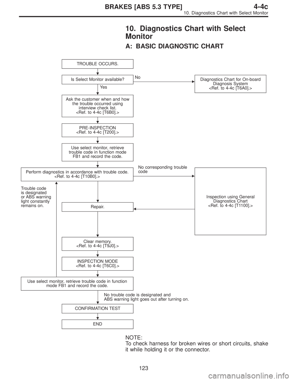
10. Diagnostics Chart with Select
Monitor
A: BASIC DIAGNOSTIC CHART
TROUBLE OCCURS.
Is Select Monitor available?
Ye s
�No
Diagnostics Chart for On-board
Diagnosis System
Ask the customer when and how
the trouble occurred using
interview check list.
PRE-INSPECTION
Use select monitor, retrieve
trouble code in function mode
FB1 and record the code.
Perform diagnostics in accordance with trouble code.
No corresponding trouble
code
�
Inspection using General
Diagnostics Chart
Trouble code
is designated
or ABS warning
light constantly
remains on.
�
Repair.�
Clear memory.
INSPECTION MODE
Use select monitor, retrieve trouble code in function
mode FB1 and record the code.
No trouble code is designated and
ABS warning light goes out after turning on.
CONFIRMATION TEST
END
NOTE:
To check harness for broken wires or short circuits, shake
it while holding it or the connector.
�
�
�
�
�
�
�
�
�
�
�
123
4-4cBRAKES [ABS 5.3 TYPE]
10. Diagnostics Chart with Select Monitor
Page 2464 of 2890
![SUBARU LEGACY 1996 Service Repair Manual B: LIST OF TROUBLE CODE
Code Display screen (FB1) Contents of diagnosis Ref. to
—ERROR 3 (1) Select monitor communication failure 4-4c [T10C0]
11 NO TROUBLEAlthough no trouble appears on the select](/manual-img/17/57433/w960_57433-2463.png "SUBARU LEGACY 1996 Service Repair Manual B: LIST OF TROUBLE CODE
Code Display screen (FB1) Contents of diagnosis Ref. to
—ERROR 3 (1) Select monitor communication failure 4-4c [T10C0]
11 NO TROUBLEAlthough no trouble appears on the select")
B: LIST OF TROUBLE CODE
Code Display screen (FB1) Contents of diagnosis Ref. to
—ERROR 3 (1) Select monitor communication failure 4-4c [T10C0]
11 NO TROUBLEAlthough no trouble appears on the select monitor display, the ABS
warning light remains on.4-4c [T10D0]
21 FR. SS HARD Open circuit or input voltage too high of FR sensor 4-4c [T10E0]
22 FR. SS SOFT Abnormal ABS sensor signal of FR sensor 4-4c [T10I0]
23 FL. SS HARD Open circuit or input voltage too high of FL sensor 4-4c [T10F0]
24 FL. SS SOFT Abnormal ABS sensor signal of FL sensor 4-4c [T10J0]
25 RR. SS HARD Open circuit or input voltage too high of RR sensor 4-4c [T10G0]
26 RR. SS SOFT Abnormal ABS sensor signal of RR sensor 4-4c [T10K0]
27 RL. SS HARD Open circuit or input voltage too high of RL sensor 4-4c [T10H0]
28 RL. SS SOFT Abnormal ABS sensor signal of RL sensor 4-4c [T10L0]
29 EITHER. SS SOFT Abnormal ABS sensor signal (any one of four) 4-4c [T10M0]
31 FR. EV VALVE Abnormal FR inlet valve 4-4c [T10N0]
32 FR. AV VALVE Abnormal FR outlet valve 4-4c [T10R0]
33 FL. EV VALVE Abnormal FL inlet valve 4-4c [T10O0]
34 FL. AV VALVE Abnormal FL outlet valve 4-4c [T10S0]
35 RR. EV VALVE Abnormal RR inlet valve 4-4c [T10P0]
36 RR. AV VALVE Abnormal RR outlet valve 4-4c [T10T0]
37 RL. EV VALVE Abnormal RL inlet valve 4-4c [T10Q0]
38 RL. AV VALVE Abnormal RL outlet valve 4-4c [T10U0]
41 ECU Abnormal ABSCM 4-4c [T10V0]
42 LOW VOLTAGE Source voltage is low. 4-4c [T10W0]
44CCM LINE A combination of AT control abnormals (ABS not in control) 4-4c [T10X0]
CCM OPEN A combination of AT control abnormals (ABS in control) 4-4c [T10Y0]
46GS POWER OVER G sensor line voltage too high 4-4c [T10Z0]
GS POWER LOW G sensor line voltage too low 4-4c [T10AA0]
51V. RELAY Abnormal valve relay 4-4c [T10AB0]
V. RELAY ON Valve relay ON failure 4-4c [T10AC0]
52M. RELAY OPEN Open circuit of motor relay 4-4c [T10AD0]
M. RELAY ON Motor relay ON failure 4-4c [T10AE0]
MOTOR Abnormal motor 4-4c [T10AF0]
54 BLS Abnormal stop light switch 4-4c [T10AG0]
56G SENSOR LINE Open or short circuit of G sensor 4-4c [T10AH0]
G SENSOR +B Battery short of G sensor 4-4c [T10AI0]
G SENSOR Hµ Abnormal G sensor high µ output 4-4c [T10AJ0]
G SENSOR STICK G sensor output is stuck. 4-4c [T10AK0]
NOTE:
High µ means high friction coefficient against road sur-
face.
124
4-4cBRAKES [ABS 5.3 TYPE]
10. Diagnostics Chart with Select Monitor
Page 2465 of 2890
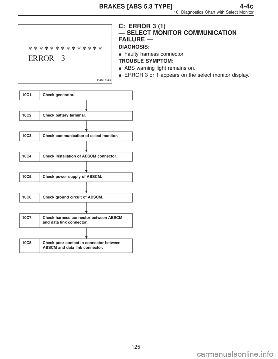
B4M0943
C: ERROR 3 (1)
—SELECT MONITOR COMMUNICATION
FAILURE—
DIAGNOSIS:
�Faulty harness connector
TROUBLE SYMPTOM:
�ABS warning light remains on.
�ERROR 3 or 1 appears on the select monitor display.
10C1.Check generator.
10C2.Check battery terminal.
10C3.Check communication of select monitor.
10C4.Check installation of ABSCM connector.
10C5.Check power supply of ABSCM.
10C6.Check ground circuit of ABSCM.
10C7.Check harness connector between ABSCM
and data link connector.
10C8.Check poor contact in connector between
ABSCM and data link connector.
�
�
�
�
�
�
�
125
4-4cBRAKES [ABS 5.3 TYPE]
10. Diagnostics Chart with Select Monitor
Page 2470 of 2890
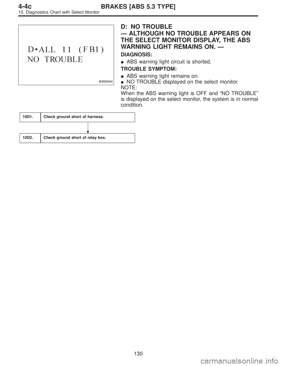
B4M0944
D: NO TROUBLE
—ALTHOUGH NO TROUBLE APPEARS ON
THE SELECT MONITOR DISPLAY, THE ABS
WARNING LIGHT REMAINS ON.—
DIAGNOSIS:
�ABS warning light circuit is shorted.
TROUBLE SYMPTOM:
�ABS warning light remains on.
�NO TROUBLE displayed on the select monitor.
NOTE:
When the ABS warning light is OFF and“NO TROUBLE”
is displayed on the select monitor, the system is in normal
condition.
10D1.Check ground short of harness.
10D2.Check ground short of relay box.
�
130
4-4cBRAKES [ABS 5.3 TYPE]
10. Diagnostics Chart with Select Monitor
Page 2472 of 2890
10D1
CHECK GROUND SHORT OF HARNESS.
1) Turn ignition switch to OFF.
2) Disconnect connector from ABSCM.
3) Disconnect connector (F50) from relay box.
4) Turn ignition switch to ON.
: Does the ABS warning light remain OFF?
: Go to step10D2.
: Repair harness between ABSCM, relay box ABS
warning light.
10D2CHECK GROUND SHORT OF RELAY
BOX.
1) Turn ignition switch to OFF.
2) Connect connector (F50) to relay box.
3) Disconnect connector (ABS1) from hydraulic unit.
4) Remove valve relay from relay box.
5) Turn ignition switch to ON.
: Does the ABS warning light remain OFF?
: Replace ABSCM.
: Replace relay box.
132
4-4cBRAKES [ABS 5.3 TYPE]
10. Diagnostics Chart with Select Monitor
Page 2621 of 2890

B5M0115B
B: ON-BOARD DIAGNOSTIC
When the airbag system is in functioning condition, the
airbag warning light will remain on for 8 seconds and go out
when the ignition switch is set to ON.
If there is any malfunction, the airbag warning light will
either stay on or off continuously. In such cases, perform
on-board diagnostic in accordance with the specified pro-
cedure to determine trouble codes.
1) Turn ignition switch ON (with engine OFF).
2) Connect DIAG. terminal�
1to No. 1 terminal of diagno-
sis connector�
2located below lower cover.
3) Check in accordance with the trouble code indicated by
the AIRBAG warning light, and record the trouble codes.
4) Turn the ignition switch “OFF” and remove the DIAG.
terminal from No.1 terminal of diagnosis connector.
B5M0116B
C: CLEAR MEMORY
After eliminating problem as per trouble code, clear
memory as follows:
Make sure ignition switch is ON (and engine off). Connect
one DIAG. terminal�
1on diagnosis connector�2terminal
No. 1.
While warning light is flashing, connect the other DIAG.
terminal�
3on terminal No. 2 for at least three seconds.
After memory is cleared, normal warning light flashing rate
resumes. (Warning light flashes every 0.6 seconds ON-
OFF operation.) Memory cannot be cleared if any problem
exists.
After clear memory and then DIAG. terminals�
1and�3,
extract from diagnosis connector�
2.
9
5-5SUPPLEMENTAL RESTRAINT SYSTEM
4. Diagnostics Chart for On-board Diagnostic System
Page 2623 of 2890
 Airbag warning light is faulty.
2) Airbag control module to airbag warning")
Trouble code/Contents of troubles Memory function Contents of diagnosis Page
Airbag warning light remains on. Not provided.1) Airbag warning light is faulty.
2) Airbag control module to airbag warning light
harness circuit is shorted or open.
3) Grounding circuit is faulty.
4) Airbag control module is faulty.
5) (AB1) and (B31) are not connected properly.36
Airbag warning light remains off. Not provided.1) Fuse No. 15 is blown.
2) Body harness circuit is open.
3) Airbag warning light is faulty.
4) Airbag main harness is faulty.
5) Airbag control module is faulty.40
Warning light
indicates trouble
code, then normal
code.Flashing trouble
code.Provided. Airbag system component parts are faulty. 42
Flashing
normal code.
Not provided.1) Airbag connector is faulty.
2) Fuse No. 16 is blown.
3) Airbag main harness is faulty.
4) Airbag control module is faulty.
5) Body harness is faulty.45
2. HOW TO READ TROUBLE CODES
The AIRBAG warning light flashes a code corresponding to
the faulty parts.
The long segment (1.2 sec on) indicates a“ten”, and the
short segment (0.3 sec on) indicates a“one”.
B5M0117A
11
5-5SUPPLEMENTAL RESTRAINT SYSTEM
4. Diagnostics Chart for On-board Diagnostic System

 Turn ignition switch to OFF.
2) Disconnect connector from ABSCM.
3) Disconnect connector (F50) from relay box.
4) Turn ignition switch to ON.
: Does the ABS warn")