Page 2820 of 2890
27. SEAT BELT WARNING SYSTEM
�LHD model
BU81-02
90
6-3WIRING DIAGRAM
6. Wiring Diagram
Page 2821 of 2890
27. SEAT BELT WARNING SYSTEM
�RHD model
BUR81-01
91
6-3WIRING DIAGRAM
6. Wiring Diagram
Page 2855 of 2890

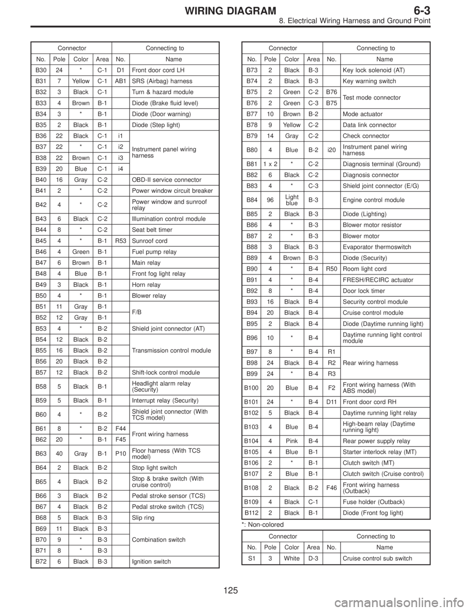
Connector Connecting to
No. Pole Color Area No. Name
B30 24 * C-1 D1 Front door cord LH
B31 7 Yellow C-1 AB1 SRS (Airbag) harness
B32 3 Black C-1 Turn & hazard module
B33 4 Brown B-1 Diode (Brake fluid level)
B34 3 * B-1 Diode (Door warning)
B35 2 Black B-1 Diode (Step light)
B36 22 Black C-1 i1
Instrument panel wiring
harness B37 22 * C-1 i2
B38 22 Brown C-1 i3
B39 20 Blue C-1 i4
B40 16 Gray C-2 OBD-II service connector
B41 2 * C-2 Power window circuit breaker
B42 4 * C-2Power window and sunroof
relay
B43 6 Black C-2 Illumination control module
B44 8 * C-2 Seat belt timer
B45 4 * B-1 R53 Sunroof cord
B46 4 Green B-1 Fuel pump relay
B47 6 Brown B-1 Main relay
B48 4 Blue B-1 Front fog light relay
B49 3 Black B-1 Horn relay
B50 4 * B-1 Blower relay
B51 11 Gray B-1
F/B
B52 12 Gray B-1
B53 4 * B-2 Shield joint connector (AT)
B54 12 Black B-2
Transmission control module B55 16 Black B-2
B56 20 Black B-2
B57 12 Black B-2 Shift-lock control module
B58 5 Black B-1Headlight alarm relay
(Security)
B59 5 Black B-1 Interrupt relay (Security)
B60 4 * B-2Shield joint connector (With
TCS model)
B61 8 * B-2 F44
Front wiring harness
B62 20 * B-1 F45
B63 40 Gray B-1 P10Floor harness (With TCS
model)
B64 2 Black B-2 Stop light switch
B65 4 Black B-2Stop & brake switch (With
cruise control)
B66 3 Black B-2 Pedal stroke sensor (TCS)
B67 4 Black B-2 Pedal stroke switch (TCS)
B68 5 Black B-3 Slip ring
B69 11 Black B-3
Combination switch B70 9 * B-3
B71 8 * B-3
B72 6 Black B-3 Ignition switchConnector Connecting to
No. Pole Color Area No. Name
B73 2 Black B-3 Key lock solenoid (AT)
B74 2 Black B-3 Key warning switch
B75 2 Green C-2 B76
Test mode connector
B76 2 Green C-3 B75
B77 10 Brown B-2 Mode actuator
B78 9 Yellow C-2 Data link connector
B79 14 Gray C-2 Check connector
B80 4 Blue B-2 i20Instrument panel wiring
harness
B81 1 x 2 * C-2 Diagnosis terminal (Ground)
B82 6 Black C-2 Diagnosis connector
B83 4 * C-3 Shield joint connector (E/G)
B84 96Light
blueB-3 Engine control module
B85 2 Black B-3 Diode (Lighting)
B86 4 * B-3 Blower motor resistor
B87 2 * B-3 Blower motor
B88 3 Black B-3 Evaporator thermoswitch
B89 4 Brown B-3 Diode (Security)
B90 4 * B-4 R50 Room light cord
B91 4 * B-4 FRESH/RECIRC actuator
B92 8 * B-4 Door lock timer
B93 16 Black B-4 Security control module
B94 20 Black B-4 Cruise control module
B95 2 Black B-4 Diode (Daytime running light)
B96 10 * B-4Daytime running light control
module
B97 8 * B-4 R1
Rear wiring harness B98 24 Black B-4 R2
B99 24 * B-4 R3
B100 20 Blue B-4 F2Front wiring harness (With
ABS model)
B101 24 * B-4 D11 Front door cord RH
B102 5 Black B-4 Daytime running light relay
B103 4 Blue B-4High-beam relay (Daytime
running light)
B104 4 Pink B-4 Rear power supply relay
B105 4 Blue B-1 Starter interlock relay (MT)
B106 2 * B-1 Clutch switch (MT)
B107 2 Blue B-1 Clutch switch (Cruise control)
B108 2 Black B-2 F46Front wiring harness
(Outback)
B109 4 Black C-1 Fuse holder (Outback)
B112 2 Black B-1 Diode (Front fog light)
*: Non-colored
Connector Connecting to
No. Pole Color Area No. Name
S1 3 White D-3 Cruise control sub switch
125
6-3WIRING DIAGRAM
8. Electrical Wiring Harness and Ground Point
Page 2857 of 2890

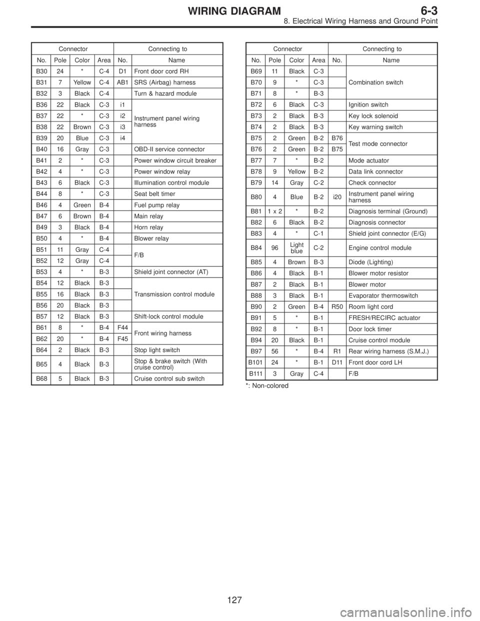
Connector Connecting to
No. Pole Color Area No. Name
B30 24 * C-4 D1 Front door cord RH
B31 7 Yellow C-4 AB1 SRS (Airbag) harness
B32 3 Black C-4 Turn & hazard module
B36 22 Black C-3 i1
Instrument panel wiring
harness B37 22 * C-3 i2
B38 22 Brown C-3 i3
B39 20 Blue C-3 i4
B40 16 Gray C-3 OBD-II service connector
B41 2 * C-3 Power window circuit breaker
B42 4 * C-3 Power window relay
B43 6 Black C-3 Illumination control module
B44 8 * C-3 Seat belt timer
B46 4 Green B-4 Fuel pump relay
B47 6 Brown B-4 Main relay
B49 3 Black B-4 Horn relay
B50 4 * B-4 Blower relay
B51 11 Gray C-4
F/B
B52 12 Gray C-4
B53 4 * B-3 Shield joint connector (AT)
B54 12 Black B-3
Transmission control module B55 16 Black B-3
B56 20 Black B-3
B57 12 Black B-3 Shift-lock control module
B61 8 * B-4 F44
Front wiring harness
B62 20 * B-4 F45
B64 2 Black B-3 Stop light switch
B65 4 Black B-3Stop & brake switch (With
cruise control)
B68 5 Black B-3 Cruise control sub switchConnector Connecting to
No. Pole Color Area No. Name
B69 11 Black C-3
Combination switch B70 9 * C-3
B71 8 * B-3
B72 6 Black C-3 Ignition switch
B73 2 Black B-3 Key lock solenoid
B74 2 Black B-3 Key warning switch
B75 2 Green B-2 B76
Test mode connector
B76 2 Green B-2 B75
B77 7 * B-2 Mode actuator
B78 9 Yellow B-2 Data link connector
B79 14 Gray C-2 Check connector
B80 4 Blue B-2 i20Instrument panel wiring
harness
B81 1 x 2 * B-2 Diagnosis terminal (Ground)
B82 6 Black B-2 Diagnosis connector
B83 4 * C-1 Shield joint connector (E/G)
B84 96Light
blueC-2 Engine control module
B85 4 Brown B-3 Diode (Lighting)
B86 4 Black B-1 Blower motor resistor
B87 2 Black B-1 Blower motor
B88 3 Black B-1 Evaporator thermoswitch
B90 2 Green B-4 R50 Room light cord
B91 5 * B-1 FRESH/RECIRC actuator
B92 8 * B-1 Door lock timer
B94 20 Black B-1 Cruise control module
B97 56 * B-4 R1 Rear wiring harness (S.M.J.)
B101 24 * B-1 D11 Front door cord LH
B111 3 Gray C-4 F/B
*: Non-colored
127
6-3WIRING DIAGRAM
8. Electrical Wiring Harness and Ground Point
Page 2859 of 2890

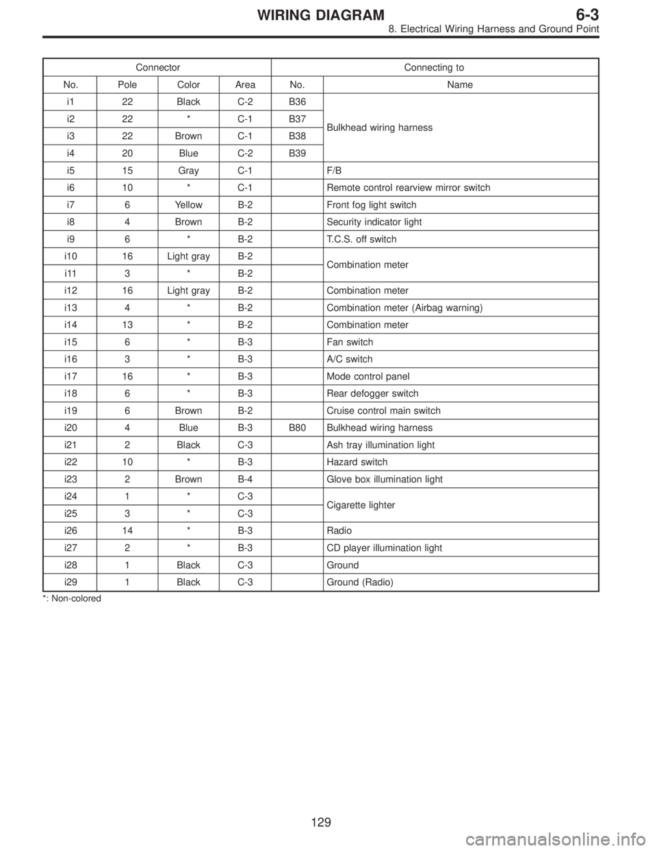
Connector Connecting to
No. Pole Color Area No. Name
i1 22 Black C-2 B36
Bulkhead wiring harness i2 22 * C-1 B37
i3 22 Brown C-1 B38
i4 20 Blue C-2 B39
i5 15 Gray C-1 F/B
i6 10 * C-1 Remote control rearview mirror switch
i7 6 Yellow B-2 Front fog light switch
i8 4 Brown B-2 Security indicator light
i9 6 * B-2 T.C.S. off switch
i10 16 Light gray B-2
Combination meter
i11 3 * B-2
i12 16 Light gray B-2 Combination meter
i13 4 * B-2 Combination meter (Airbag warning)
i14 13 * B-2 Combination meter
i15 6 * B-3 Fan switch
i16 3 * B-3 A/C switch
i17 16 * B-3 Mode control panel
i18 6 * B-3 Rear defogger switch
i19 6 Brown B-2 Cruise control main switch
i20 4 Blue B-3 B80 Bulkhead wiring harness
i21 2 Black C-3 Ash tray illumination light
i22 10 * B-3 Hazard switch
i23 2 Brown B-4 Glove box illumination light
i24 1 * C-3
Cigarette lighter
i25 3 * C-3
i26 14 * B-3 Radio
i27 2 * B-3 CD player illumination light
i28 1 Black C-3 Ground
i29 1 Black C-3 Ground (Radio)
*: Non-colored
129
6-3WIRING DIAGRAM
8. Electrical Wiring Harness and Ground Point
Page 2861 of 2890
Connector Connecting to
No. Pole Color Area No. Name
i1 22 Black C-4 B36
Bulkhead wiring harness i2 22 * C-4 B37
i3 22 Brown C-4 B38
i4 20 Blue C-4 B39
i5 15 Gray C-4 F/B
i6 10 * C-4 Remote control rearview mirror switch
i10 16 Light gray B-3
Combination meter
i11 3 * B-3
i12 16 Light gray B-3 Combination meter
i13 4 * B-3 Combination meter (Airbag warning)
i14 13 * B-3 Combination meter
i15 6 * B-2 Fan switch
i17 16 Black B-2 Mode control panel
i18 6 * B-3 Rear defogger switch
i19 6 Brown B-3 Cruise control main switch
i20 4 Blue B-2 B80 Bulkhead wiring harness
i22 10 * B-2 Hazard switch
i23 2 Brown B-2 Glove box illumination light
i24 1 * C-2
Cigarette lighter
i25 3 * C-2
i26 14 * B-2 Radio
i28 1 Black C-2 Ground
i29 1 Black C-2 Ground (Radio)
*: Non-colored
131
6-3WIRING DIAGRAM
8. Electrical Wiring Harness and Ground Point
Page 2880 of 2890

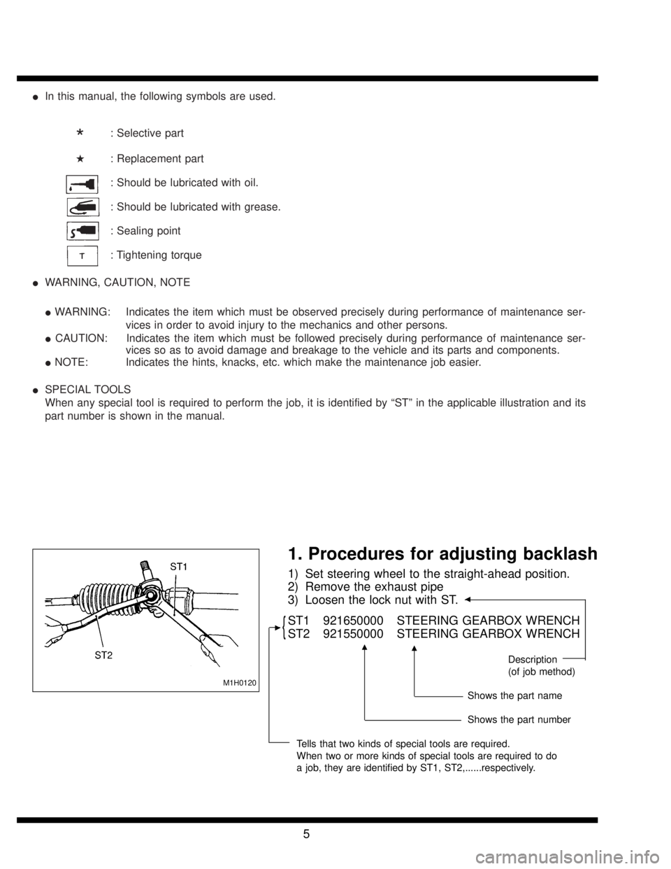
�In this manual, the following symbols are used.
*: Selective part
�: Replacement part
: Should be lubricated with oil.
: Should be lubricated with grease.
: Sealing point
: Tightening torque
�WARNING, CAUTION, NOTE
�WARNING: Indicates the item which must be observed precisely during performance of maintenance ser-
vices in order to avoid injury to the mechanics and other persons.
�CAUTION: Indicates the item which must be followed precisely during performance of maintenance ser-
vices so as to avoid damage and breakage to the vehicle and its parts and components.
�NOTE: Indicates the hints, knacks, etc. which make the maintenance job easier.
�SPECIAL TOOLS
When any special tool is required to perform the job, it is identified by“ST”in the applicable illustration and its
part number is shown in the manual.
M1H0120
1. Procedures for adjusting backlash
1) Set steering wheel to the straight-ahead position.
2) Remove the exhaust pipe
3) Loosen the lock nut with ST.
�
{ST1 921650000 STEERING GEARBOX WRENCH
ST2 921550000 STEERING GEARBOX WRENCH
Description
(of job method)
Shows the part name
Shows the part number
Tells that two kinds of special tools are required.
When two or more kinds of special tools are required to do
a job, they are identified by ST1, ST2,......respectively.
�
��
5
Page 2884 of 2890
�In this manual, the following symbols are used.
Circuit tester
Voltage measurement
Circuit tester
Resistance measurement
The arrow indicates that insertion of the probe or numbering of the connector pins is
made from the side.
The arrow indicates that insertion of the probe or numbering of the connector pins is
made from the side.
Oscilloscope
Oscilloscope positive probe
Oscilloscope earth head
�WARNING, CAUTION, NOTE
�WARNING: Indicates the item which must be observed precisely during performance of maintenance ser-
vices in order to avoid injury to the mechanics and other persons.
�CAUTION: Indicates that item which must be followed precisely during performance of maintenance ser-
vices so as to avoid damage and breakage to the vehicle and its parts and components.
�NOTE: Indicates the hints, knacks, etc. which make the maintenance job easier.
5