Page 2238 of 2890
B4M0718A
1. CHECK HARNESS CONNECTOR BETWEEN ABS/
TCS CONTROL MODULE AND TCS OFF INDICATOR
LIGHT.
1) Turn ignition switch OFF.
2) Disconnect all connectors from ABS/TCS control mod-
ule.
3) Turn ignition switch ON.
4) Measure voltage between ABS/TCS control module
connector and body.
Connector & terminal / Specified voltage:
(P6) No. 10—body / 10—13 V
27
4-4bBRAKES
7. Diagnostics Chart for Warning Light Circuit Failure
Page 2239 of 2890
F: TCS OPERATING INDICATOR LIGHT DOES
NOT GO OFF.
—WHEN STARTING THE ENGINE, ABS
WARNING, TCS WARNING AND TCS OFF
INDICATOR LIGHTS COME ON AND GO OFF
PROPERLY BUT TCS OPERATING
INDICATOR LIGHT ONLY KEEPS ON.—
1. Check harness connector between ABS/TCS
control module and TCS operating indicator
light.
OK
�Not OK
Repair harness/connector.
Replace ABS/TCS control module.
B4M0398
�
28
4-4bBRAKES
7. Diagnostics Chart for Warning Light Circuit Failure
Page 2240 of 2890
B4M0719A
1. CHECK HARNESS CONNECTOR BETWEEN ABS/
TCS CONTROL MODULE AND TCS OPERATING
INDICATOR LIGHT.
1) Turn ignition switch OFF.
2) Disconnect all connectors from ABS/TCS control mod-
ule.
3) Turn ignition switch ON.
4) Measure voltage between ABS/TCS control module
connector and body.
Connector & terminal / Specified voltage:
(P6) No. 11—body / 10—13 V
29
4-4bBRAKES
7. Diagnostics Chart for Warning Light Circuit Failure
Page 2241 of 2890
G: TCS OFF SWITCH DOES NOT FUNCTION.
—TCS OFF INDICATOR LIGHT COMES ON
AND GOES OFF PROPERLY WHEN
STARTING THE ENGINE, WHILE THIS LIGHT
NEITHER COMES ON NOR GOES OFF WHEN
PUSHING THE TCS OFF SWITCH.—
1. Check TCS OFF switch
OK
�Not OK
Replace TCS OFF switch.
2. Check harness connector between ABS/TCS
control module and TCS OFF switch.
OK
�Not OK
Repair harness/connector.
Replace ABS/TCS control module.
B4M0535
�
�
30
4-4bBRAKES
7. Diagnostics Chart for Warning Light Circuit Failure
Page 2242 of 2890
B4M0720A
1. CHECK TCS OFF SWITCH.
1) Turn ignition switch OFF.
2) Disconnect connector from TCS OFF switch.
3) Measure resistance between TCS OFF switch termi-
nals.
Connector & terminal / Specified resistance:
(i9) No. 5—No.3/1Ωor less
(When the switch is pressed,
turns ON.)
/1MΩor less
(When the switch is released,
turns OFF.)
B4M0401A
2. CHECK HARNESS CONNECTOR BETWEEN ABS/
TCS CONTROL MODULE AND TCS OFF SWITCH.
1) Turn ignition switch OFF.
2) Disconnect connector to TCS OFF switch.
3) Disconnect connector from ABS/TCS control module.
4) Measure resistance between ABS/TCS control module
connector terminals.
Connector & terminal / Specified resistance:
(P7) No. 16—body / 1Ωor less (When the switch
is pressed, turns ON.)
/1MΩor more (When the
switch is released, turns OFF.)
31
4-4bBRAKES
7. Diagnostics Chart for Warning Light Circuit Failure
Page 2243 of 2890
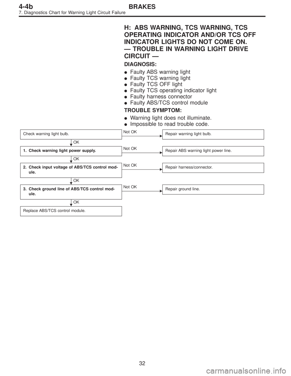
H: ABS WARNING, TCS WARNING, TCS
OPERATING INDICATOR AND/OR TCS OFF
INDICATOR LIGHTS DO NOT COME ON.
—TROUBLE IN WARNING LIGHT DRIVE
CIRCUIT—
DIAGNOSIS:
�Faulty ABS warning light
�Faulty TCS warning light
�Faulty TCS OFF light
�Faulty TCS operating indicator light
�Faulty harness connector
�Faulty ABS/TCS control module
TROUBLE SYMPTOM:
�Warning light does not illuminate.
�Impossible to read trouble code.
Check warning light bulb.
OK
�Not OK
Repair warning light bulb.
1. Check warning light power supply.
OK
�Not OK
Repair ABS warning light power line.
2. Check input voltage of ABS/TCS control mod-
ule.
OK
�Not OK
Repair harness/connector.
3. Check ground line of ABS/TCS control mod-
ule.
OK
�Not OK
Repair ground line.
Replace ABS/TCS control module.
�
�
�
�
32
4-4bBRAKES
7. Diagnostics Chart for Warning Light Circuit Failure
Page 2244 of 2890
B4M0402
B4M0403A
1. CHECK WARNING LIGHT POWER SUPPLY.
1) Turn ignition switch OFF.
2) Disconnect combination meter.
3) Turn ignition switch ON.
4) Measure voltage between combination meter connector
and body.
Connector & terminal / Specified voltage:
(i14) No. 11—body / 10—13 V
33
4-4bBRAKES
7. Diagnostics Chart for Warning Light Circuit Failure
Page 2245 of 2890
B4M0404A
2. CHECK INPUT VOLTAGE OF ABS/TCS CONTROL
MODULE.
1) Turn ignition switch OFF and connect combination
meter connector.
2) Disconnect all connectors from ABS/TCS control mod-
ule.
3) Remove ABS/TCS valve relay.
4) Turn ignition switch ON.
5) Measure voltage between ABS/TCS control module and
body.
Connector & terminal / Specified voltage:
ABS warning:
(P6) No. 2—body / 10—13 V
TCS warning:
(P6) No. 3—body / 10—13 V
TCS operation:
(P6) No. 11—body / 10—13 V
TCS OFF:
(P6) No. 10—body / 10—13 V
B4M0405A
3. CHECK GROUND LINE OF ABS/TCS CONTROL
MODULE.
Measure resistance between ABS/TCS control module and
body.
Connector & terminal / Specified resistance:
(P4) No. 6—body / 1Ωor less
(P5) No. 5—body / 1Ωor less
(P7) No. 15—body / 1Ωor less
34
4-4bBRAKES
7. Diagnostics Chart for Warning Light Circuit Failure
 Turn ignition switch OFF.
2) Disconnect all connectors from ABS/TCS control mod-
ule.
3) Turn igniti")

 Turn ignition switch OFF.
2) Disconnect all connectors from ABS/TCS control mod-
ule.
3) Turn")

 Turn ignition switch OFF.
2) Disconnect connector from TCS OFF switch.
3) Measure resistance between TCS OFF switch termi-
nals.
Connector & terminal / Specified r")
 Turn ignition switch OFF.
2) Disconnect combination meter.
3) Turn ignition switch ON.
4) Measure voltage between combination meter connector
a")
 Turn ignition switch OFF and connect combination
meter connector.
2) Disconnect all connectors from ABS/TCS control mod-
ule.
3) Remove AB")