Page 1713 of 2890
B6M0358
3) Remove nuts which secure actuator.
4) Remove actuator while disconnecting vacuum hose.
Tightening torque:
7.4±1.5 N⋅m (0.75±0.15 kg-m, 5.4±1.1 ft-lb)
B6M0359A
4. VACUUM PUMP AND VALVES
1) Disconnect connector from vacuum pump.
2) Remove bolts which secure vacuum pump.
3) Remove A/C receiver/drier bracket.
4) Remove vacuum pump while disconnecting vacuum
hose.
Tightening torque:
7.4±1.5 N⋅m (0.75±0.15 kg-m, 5.4±1.1 ft-lb)
5. STOP AND BRAKE SWITCH
Refer to 4-5 [C100] (MT) or 4-5 [C200] (AT) as for removal
and installation of stop and brake switch.
6. CLUTCH SWITCH (MT)
Refer to 4-5 [C100] as for removal and installation of clutch
switch.
7. INHIBITOR SWITCH (AT)
Refer to 3-2 [W4A3] as for removal and installation of
inhibitor switch.
G6M0095
8. CRUISE CONTROL MODULE
1) Disconnect battery ground cable.
B3M0377A
2) Remove lower cover and then disconnect connector.
49
6-2SERVICE PROCEDURE
21. Cruise Control
Page 1727 of 2890
1. Starter Interlock System (MT Model)
A: DIAGNOSTICS PROCEDURE
1. Check main power supply for starter motor.
OK
�Not OK
�Recharge the battery.
�Repair or replace wiring harness.
2. Check power supply for magnet coil of starter
motor.
Not OK
�OK
Repair or replace starter motor.
3. Check power supply for starter interlock relay.
OK
�Not OK
Repair or replace wiring harness.
4. Check starter interlock relay.
OK
�Not OK
Replace starter interlock relay.
5. Check clutch switch.
OK
�Not OK
Adjust or replace clutch switch.
6. Check harness connector between starter
interlock relay and starter motor.
OK
�Not OK
Repair or replace wiring harness.
7. Check harness connector between starter
interlock relay and clutch switch.
OK
�Not OK
Repair or replace wiring harness.
8. Check ground circuit of clutch switch.
OK
�Not OK
Repair or replace wiring harness.
System is OK
�
�
�
�
�
�
�
�
63
6-2DIAGNOSTICS
1. Starter Interlock System (MT Model)
Page 1728 of 2890
B6M0383A
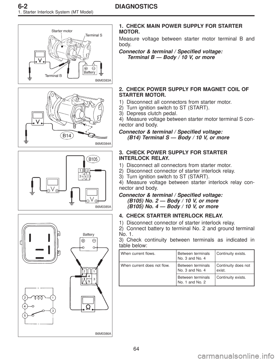
1. CHECK MAIN POWER SUPPLY FOR STARTER
MOTOR.
Measure voltage between starter motor terminal B and
body.
Connector & terminal / Specified voltage:
Terminal B—Body / 10 V, or more
B6M0384A
2. CHECK POWER SUPPLY FOR MAGNET COIL OF
STARTER MOTOR.
1) Disconnect all connectors from starter motor.
2) Turn ignition switch to ST (START).
3) Depress clutch pedal.
4) Measure voltage between starter motor terminal S con-
nector and body.
Connector & terminal / Specified voltage:
(B14) Terminal S—Body / 10 V, or more
B6M0385A
3. CHECK POWER SUPPLY FOR STARTER
INTERLOCK RELAY.
1) Disconnect all connectors from starter motor.
2) Disconnect connector of starter interlock relay.
3) Turn ignition switch to ST (START).
4) Measure voltage between starter interlock relay con-
nector and body.
Connector & terminal / Specified voltage:
(B105) No. 2—Body / 10 V, or more
(B105) No. 4—Body / 10 V, or more
B6M0386A
4. CHECK STARTER INTERLOCK RELAY.
1) Disconnect connector of starter interlock relay.
2) Connect battery to terminal No. 2 and ground terminal
No. 1.
3) Check continuity between terminals as indicated in
table below:
When current flows. Between terminals
No. 3 and No. 4Continuity exists.
When current does not flow. Between terminals
No. 3 and No. 4Continuity does not
exist.
Between terminals
No. 1 and No. 2Continuity exists.
64
6-2DIAGNOSTICS
1. Starter Interlock System (MT Model)
Page 1729 of 2890
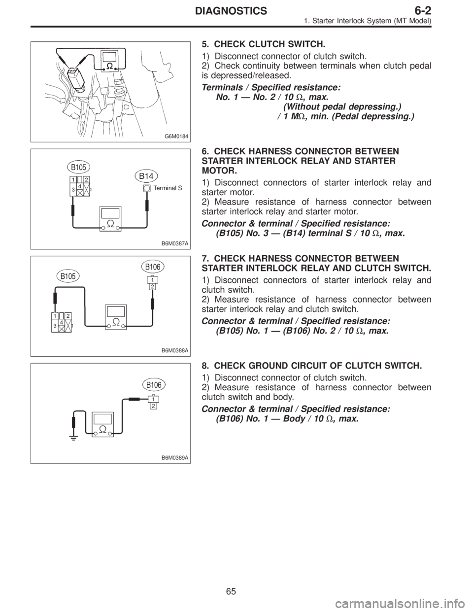
G6M0184
5. CHECK CLUTCH SWITCH.
1) Disconnect connector of clutch switch.
2) Check continuity between terminals when clutch pedal
is depressed/released.
Terminals / Specified resistance:
No. 1—No.2/10Ω, max.
(Without pedal depressing.)
/1MΩ, min. (Pedal depressing.)
B6M0387A
6. CHECK HARNESS CONNECTOR BETWEEN
STARTER INTERLOCK RELAY AND STARTER
MOTOR.
1) Disconnect connectors of starter interlock relay and
starter motor.
2) Measure resistance of harness connector between
starter interlock relay and starter motor.
Connector & terminal / Specified resistance:
(B105) No. 3—(B14) terminalS/10Ω, max.
B6M0388A
7. CHECK HARNESS CONNECTOR BETWEEN
STARTER INTERLOCK RELAY AND CLUTCH SWITCH.
1) Disconnect connectors of starter interlock relay and
clutch switch.
2) Measure resistance of harness connector between
starter interlock relay and clutch switch.
Connector & terminal / Specified resistance:
(B105) No. 1—(B106) No.2/10Ω, max.
B6M0389A
8. CHECK GROUND CIRCUIT OF CLUTCH SWITCH.
1) Disconnect connector of clutch switch.
2) Measure resistance of harness connector between
clutch switch and body.
Connector & terminal / Specified resistance:
(B106) No. 1—Body / 10Ω, max.
65
6-2DIAGNOSTICS
1. Starter Interlock System (MT Model)
Page 1780 of 2890
B: AUTOMATIC TRANSMISSION
1. ELECTRONIC-HYDRAULIC CONTROL SYSTEM
The electronic-hydraulic control system consists of various
sensors and switches, a transmission control module
(TCM) and the hydraulic controller including solenoid
valves. The system controls the transmission proper
including shift control, lock-up control, overrunning clutch
control, line pressure control and shift timing control. It also
controls the AWD transfer clutch. In other words, the sys-
tem detects various operating conditions from various input
signals and sends output signals to shift solenoids 1, 2 and
3 and duty solenoids A, B and C (a total of six solenoids).
12
2-7ON-BOARD DIAGNOSTICS II SYSTEM
1. General
Page 1826 of 2890
G3M0151
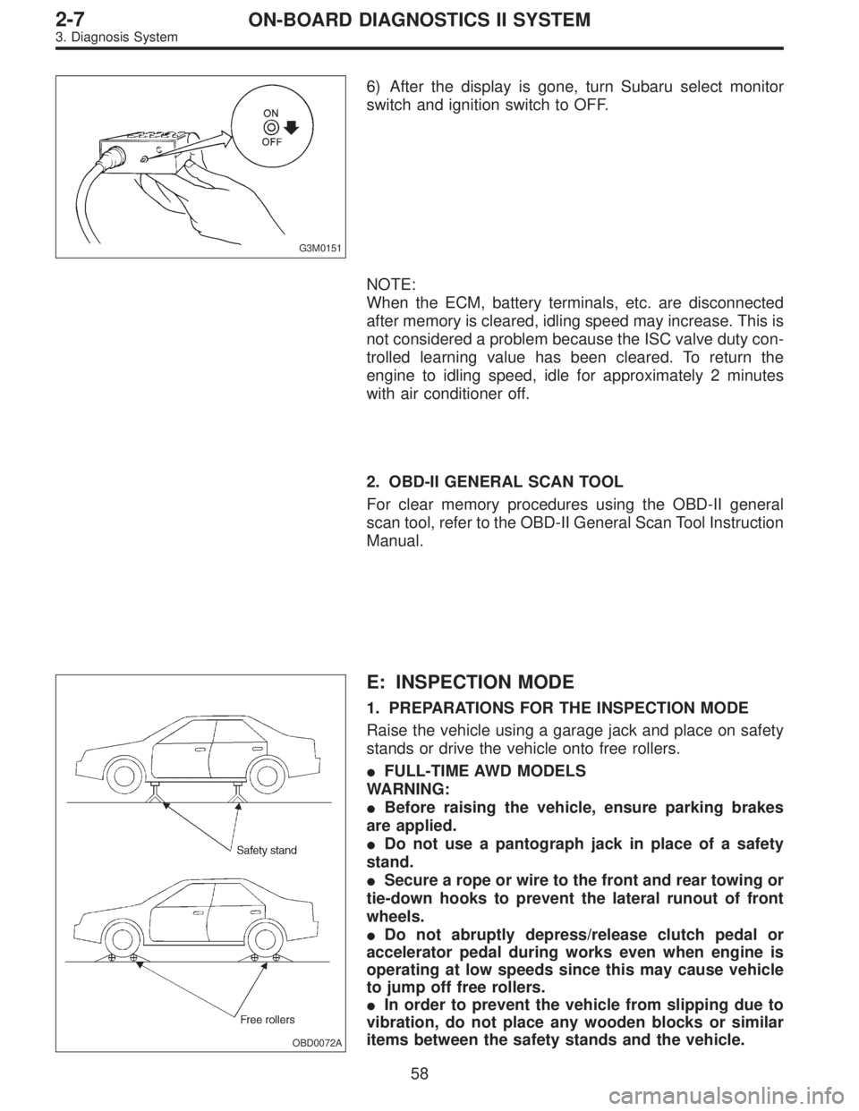
6) After the display is gone, turn Subaru select monitor
switch and ignition switch to OFF.
NOTE:
When the ECM, battery terminals, etc. are disconnected
after memory is cleared, idling speed may increase. This is
not considered a problem because the ISC valve duty con-
trolled learning value has been cleared. To return the
engine to idling speed, idle for approximately 2 minutes
with air conditioner off.
2. OBD-II GENERAL SCAN TOOL
For clear memory procedures using the OBD-II general
scan tool, refer to the OBD-II General Scan Tool Instruction
Manual.
OBD0072A
E: INSPECTION MODE
1. PREPARATIONS FOR THE INSPECTION MODE
Raise the vehicle using a garage jack and place on safety
stands or drive the vehicle onto free rollers.
�FULL-TIME AWD MODELS
WARNING:
�Before raising the vehicle, ensure parking brakes
are applied.
�Do not use a pantograph jack in place of a safety
stand.
�Secure a rope or wire to the front and rear towing or
tie-down hooks to prevent the lateral runout of front
wheels.
�Do not abruptly depress/release clutch pedal or
accelerator pedal during works even when engine is
operating at low speeds since this may cause vehicle
to jump off free rollers.
�In order to prevent the vehicle from slipping due to
vibration, do not place any wooden blocks or similar
items between the safety stands and the vehicle.
58
2-7ON-BOARD DIAGNOSTICS II SYSTEM
3. Diagnosis System
Page 1827 of 2890
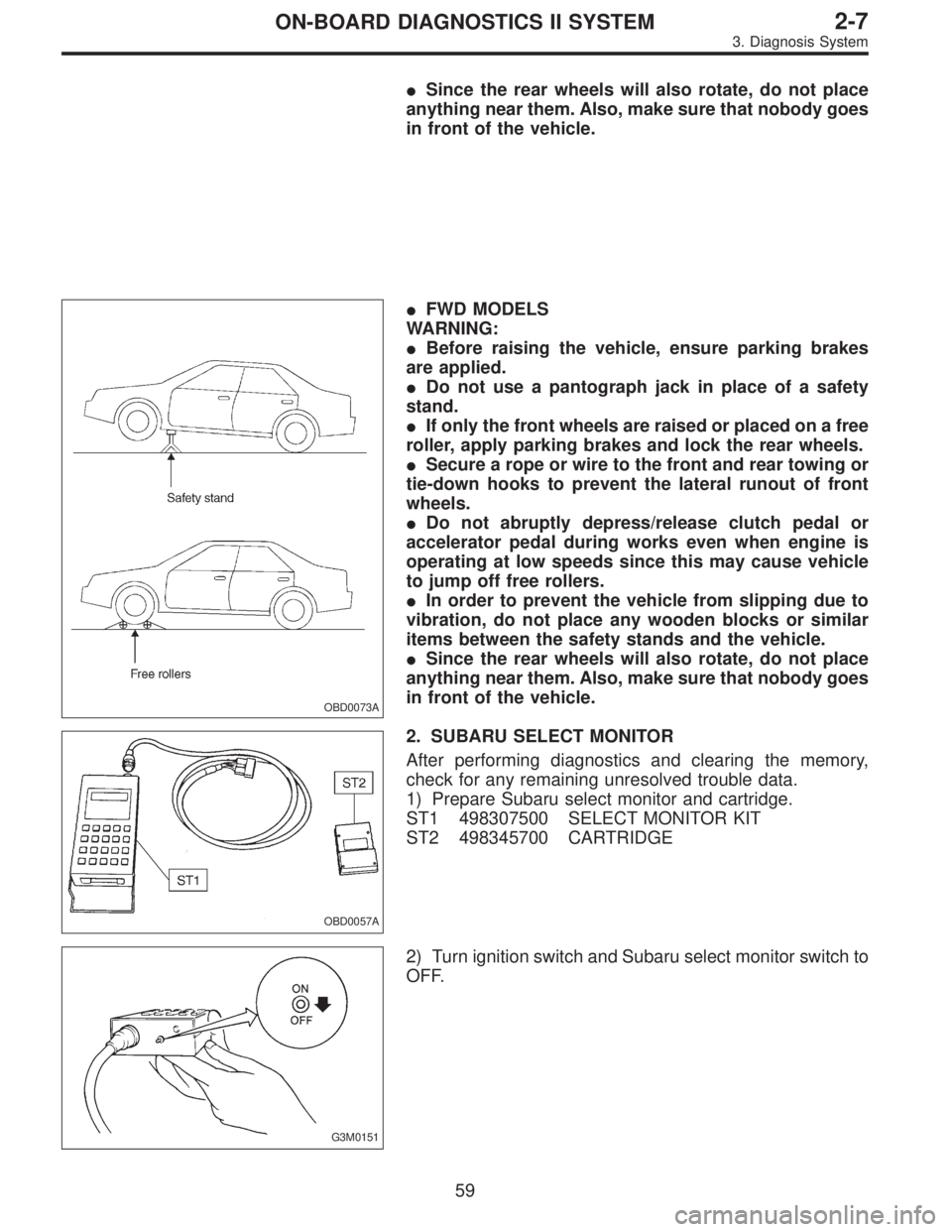
�Since the rear wheels will also rotate, do not place
anything near them. Also, make sure that nobody goes
in front of the vehicle.
OBD0073A
�FWD MODELS
WARNING:
�Before raising the vehicle, ensure parking brakes
are applied.
�Do not use a pantograph jack in place of a safety
stand.
�If only the front wheels are raised or placed on a free
roller, apply parking brakes and lock the rear wheels.
�Secure a rope or wire to the front and rear towing or
tie-down hooks to prevent the lateral runout of front
wheels.
�Do not abruptly depress/release clutch pedal or
accelerator pedal during works even when engine is
operating at low speeds since this may cause vehicle
to jump off free rollers.
�In order to prevent the vehicle from slipping due to
vibration, do not place any wooden blocks or similar
items between the safety stands and the vehicle.
�Since the rear wheels will also rotate, do not place
anything near them. Also, make sure that nobody goes
in front of the vehicle.
OBD0057A
2. SUBARU SELECT MONITOR
After performing diagnostics and clearing the memory,
check for any remaining unresolved trouble data.
1) Prepare Subaru select monitor and cartridge.
ST1 498307500 SELECT MONITOR KIT
ST2 498345700 CARTRIDGE
G3M0151
2) Turn ignition switch and Subaru select monitor switch to
OFF.
59
2-7ON-BOARD DIAGNOSTICS II SYSTEM
3. Diagnosis System
Page 1829 of 2890
OBD0060
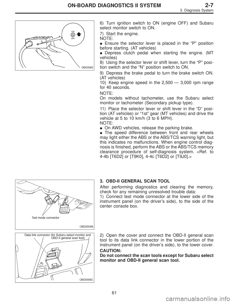
6) Turn ignition switch to ON (engine OFF) and Subaru
select monitor switch to ON.
7) Start the engine.
NOTE:
�Ensure the selector lever is placed in the“P”position
before starting. (AT vehicles)
�Depress clutch pedal when starting the engine. (MT
vehicles)
8) Using the selector lever or shift lever, turn the“P”posi-
tion switch and the“N”position switch to ON.
9) Depress the brake pedal to turn the brake switch ON.
(AT vehicles)
10) Keep engine speed in the 2,500—3,000 rpm range
for 40 seconds.
NOTE:
On models without tachometer, use the Subaru select
monitor or tachometer (Secondary pickup type).
11) Place the selector lever or shift lever in the“D”posi-
tion (AT vehicles) or“1st”gear (MT vehicles) and drive the
vehicle at 5 to 10 km/h (3 to 6 MPH).
NOTE:
�On AWD vehicles, release the parking brake.
�The speed difference between front and rear wheels
may light either the ABS or the ABS/TCS warning light, but
this indicates no malfunctions. When engine control diag-
nosis is finished, perform the ABS or the ABS/TCS memory
clearance procedure of self-diagnosis system.
4-4b [T6D2] or [T9K0], 4-4c [T6D2] or [T9J0].>
OBD0005B
3. OBD-II GENERAL SCAN TOOL
After performing diagnostics and clearing the memory,
check for any remaining unresolved trouble data:
1) Connect test mode connector at the lower side of the
instrument panel (on the driver’s side), to the side of the
center console box.
OBD0006C
2) Open the cover and connect the OBD-II general scan
tool to its data link connector in the lower portion of the
instrument panel (on the driver’s side), to the lower cover.
CAUTION:
Do not connect the scan tools except for Subaru select
monitor and OBD-II general scan tool.
61
2-7ON-BOARD DIAGNOSTICS II SYSTEM
3. Diagnosis System