Page 1351 of 2890
2. Clutch Cable
A: REMOVAL
1) Disconnect clutch cable from release lever.
B4M0160A
2) Depress clutch pedal to the floor.
3) Remove clutch cable clamp from pedal bracket.
4) Disconnect clutch cable from pedal bracket and pedal
end.
5) Remove clutch cable from body.
CAUTION:
Before removing clutch cable from toe board, remove
grommet. Slowly remove clutch cable, being careful
not to scratch it.
G4M0332
B: INSTALLATION
1) Clean clutch pedal fitting hole, and apply grease. Con-
nect clutch cable to clutch pedal.
2) Fit clutch pedal to pedal bolt, and connect clutch cable
to bracket with clamp.
3) Connect clutch cable end to pedal end.
4) Connect clutch cable from release lever.
5) Install grommet to toe board.
6) Adjustment after cable installation.
15
4-5SERVICE PROCEDURE
2. Clutch Cable
Page 1354 of 2890
1. Pedal System and Control Cables
Trouble Corrective action
Excessively worn brake pedal pad Replace.
Failure of clutch and/or accelerator pedals to operate Connect cables correctly.
Stop light switch does not light up. Adjust position of stop light switch.
Stop light switch is not smooth and/or stroke is not correct. Replace.
Insufficient pedal play Adjust pedal play.
Clutch and/or brake pedal free play insufficient Adjust pedal free play.
Maladjustment of brake pedal or booster push rod Inspect and adjust.
Excessively worn and damaged pedal shaft and/or bushing Replace bushing and/or shaft with new one.
18
4-5DIAGNOSTICS
1. Pedal System and Control Cables
Page 1375 of 2890

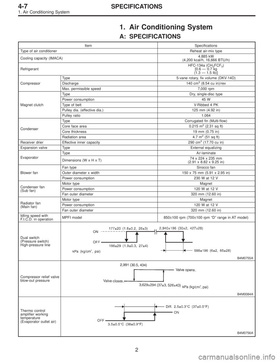
1. Air Conditioning System
A: SPECIFICATIONS
Item Specifications
Type of air conditionerReheat air-mix type
Cooling capacity (IMACA)4.885 kW
(4,200 kcal/h, 16,666 BTU/h)
RefrigerantHFC-134a (CH
2FCF3)
[0.6 — 0.7 kg
(1.3 — 1.5 lb)]
CompressorType 5-vane rotary, fix volume (DKV-14D)
Discharge 140 cm
3(8.54 cu in)/rev
Max. permissible speed 7,000 rpm
Magnet clutchTy p eDry, single-disc type
Power consumption 45 W
Type of belt V-Ribbed 4 PK
Pulley dia. (effective dia.) 125 mm (4.92 in)
Pulley ratio1.064
CondenserType Corrugated fin (Multi-flow)
Core face area 0.215 m
2(2.31 sq ft)
Core thickness 19 mm (0.75 in)
Radiation area 4.7 m
2(51 sq ft)
Receiver drier Effective inner capacity 290 cm3(17.70 cu in)
Expansion valve TypeExternal equalizing
EvaporatorTy p eA�-laminate
Dimensions (W x H x T)74 x 224 x 235 mm
(2.91 x 8.82 x 9.25 in)
Blower fanFan typeSirocco fan
Outer diameter x width 150 x 75 mm (5.91 x 2.95 in)
Power consumption 230 W at 12 V
Condenser fan
(Sub fan)Motor typeMagnet
Power consumption 120 W at 12 V
Fan outer diameter 320 mm (12.60 in)
Radiator fan
(Main fan)Motor typeMagnet
Power consumption 120 W at 12 V
Fan outer diameter 320 mm (12.60 in)
Idling speed with
F.I.C.D. in operationMPFI model 850±100 rpm (700±100 rpm “D” range in AT model)
Dual switch
(Pressure switch)
High-pressure line
B4M0755A
Compressor relief valve
blow-out pressure
B4M0084A
Thermo control
amplifier working
temperature
(Evaporator outlet air)
B4M0756A
2
4-7SPECIFICATIONS
1. Air Conditioning System
Page 1397 of 2890

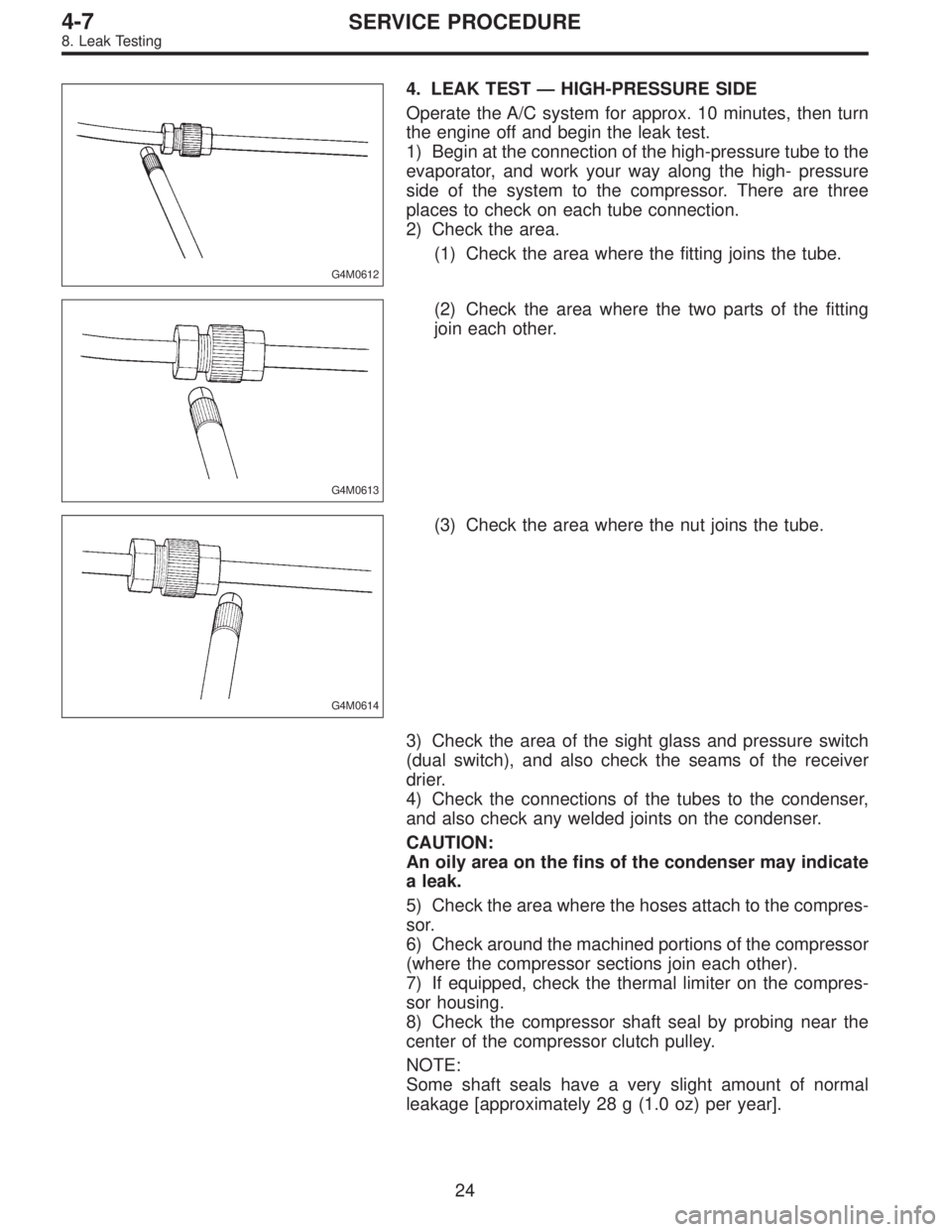
G4M0612
4. LEAK TEST — HIGH-PRESSURE SIDE
Operate the A/C system for approx. 10 minutes, then turn
the engine off and begin the leak test.
1) Begin at the connection of the high-pressure tube to the
evaporator, and work your way along the high- pressure
side of the system to the compressor. There are three
places to check on each tube connection.
2) Check the area.
(1) Check the area where the fitting joins the tube.
G4M0613
(2) Check the area where the two parts of the fitting
join each other.
G4M0614
(3) Check the area where the nut joins the tube.
3) Check the area of the sight glass and pressure switch
(dual switch), and also check the seams of the receiver
drier.
4) Check the connections of the tubes to the condenser,
and also check any welded joints on the condenser.
CAUTION:
An oily area on the fins of the condenser may indicate
a leak.
5) Check the area where the hoses attach to the compres-
sor.
6) Check around the machined portions of the compressor
(where the compressor sections join each other).
7) If equipped, check the thermal limiter on the compres-
sor housing.
8) Check the compressor shaft seal by probing near the
center of the compressor clutch pulley.
NOTE:
Some shaft seals have a very slight amount of normal
leakage [approximately 28 g (1.0 oz) per year].
24
4-7SERVICE PROCEDURE
8. Leak Testing
Page 1404 of 2890
11. Compressor
Compressor is a swash plate type. When trouble occurs,
replace compressor as a single unit.
B4M0090
A: COMPRESSOR CLUTCH INSPECTION
Compressor clutch trouble is often caused by clutch slip-
page and noise. Check and take corrective measures, as
required.
1) Remove belt cover.
2) Check that clearance between drive plate and pulley
over the entire perimeter is within specifications.
Clearance:
0.3 — 0.6 mm (0.012 — 0.024 in)
B4M0091
3) Check that voltage applied to magnetic coil is at least
10.5 volts.
4) When noise is noted, check that it originates in either
compressor or pulley bearing.
30
4-7SERVICE PROCEDURE
11. Compressor
Page 1424 of 2890
5. Compressor Clutch Diagnosis
Compressor clutch is not engaged.
Check both 10 A fuse for A/C.
Fuse O.K. Fuse blown
Determine cause of blown fuse. Replace faulty part(s)
and fuse.
Does 12 volts exist in control panel connector (R/B)?
Ye s
�No
Faulty harness
Does 12 volts exist in control panel connector (B/W)?
Ye s
�No
Faulty A/C switch
Does 12 volts exist in dual pressure switch connector
(G/Y)?
Ye s
�No
Faulty harness
Does 12 volts exist in dual pressure switch connector
(Br/Y)?
Ye s
�No
Faulty dual pressure switch
Does 12 volts exist in A/C relay connector (Br/R) and
(W)?
Ye s
�No
Faulty harness
Does 12 volts exist in A/C relay connector (R/W)?
Ye s
�No
Does 0 volts exist in A/C relay connector (Br/Y)?
Ye s N o
Faulty A/C relay
To�B
Does 12 volts exist in thermoswitch connector (R/W)?
Ye s
�No
Faulty harness
Does 12 volts exist in thermoswitch connector (L/R)?
Ye s
�No
Faulty thermoswitch
To�A
�
�
�
�
�
�
�
�
��
�
�
�
47
4-7DIAGNOSTICS
5. Compressor Clutch Diagnosis
Page 1425 of 2890
�A
Does 12 volts exist in A/C cut relay connector (L/Y)
and (Br/R)?
Ye s
�No
Faulty harness
Does 12 volts exist in A/C cut relay connector (Y/G)?
Ye s
�No
Does 0 volts exist in A/C cut relay connector (G)?
Ye s N o
Faulty A/C cut relay
Check engine control
module.
Does 12 volts exist in compressor connector (Y/G)?
Ye s
�No
Faulty harness
Faulty magnet clutch
�B
Does 12 volts exist in thermo control amplifier connec-
tor (Br/R)?
Ye s
�No
Faulty harness
Does 0 volts exist in thermo control amplifier connec-
tor (R)?
Ye s
�No
Faulty harness or blower switch
Does 0 volts exist in thermo control amplifier connec-
tor (W)?
Ye s
�No
Faulty thermo control amplifier
Faulty harness
�
�
��
�
�
�
�
�
�
48
4-7DIAGNOSTICS
5. Compressor Clutch Diagnosis
Page 1503 of 2890

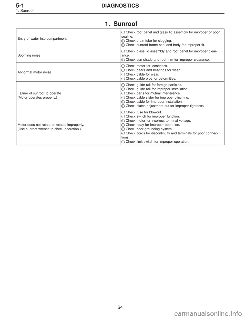
1. Sunroof
Entry of water into compartment�
1Check roof panel and glass lid assembly for improper or poor
sealing.
�
2Check drain tube for clogging.
�
3Check sunroof frame seal and body for improper fit.
Booming noise�
1Check glass lid assembly and roof panel for improper clear-
ance.
�
2Check sun shade and roof trim for improper clearance.
Abnormal motor noise�
1Check motor for looseness.
�
2Check gears and bearings for wear.
�
3Check cable for wear.
�
4Check cable pipe for deformities.
Failure of sunroof to operate
(Motor operates properly.)�
1Check guide rail for foreign particles.
�
2Check guide rail for improper installation.
�
3Check parts for mutual interference.
�
4Check cable slider for improper clinching.
�
5Check cable for improper installation.
�
6Check clutch adjustment nut for improper tightness.
Motor does not rotate or rotates improperly.
(Use sunroof wrench to check operation.)�
1Check fuse for blowout.
�
2Check switch for improper function.
�
3Check motor for incorrect terminal voltage.
�
4Check relay for improper operation.
�
5Check poor grounding system.
�
6Check cords for discontinuity and terminals for poor connec-
tions.
�
7Check limit switch for improper operation.
64
5-1DIAGNOSTICS
1. Sunroof