Page 2195 of 2890

2. ON←→OFF SIGNAL LIST
Mode LED No. Signal name Display LED“ON”requirements Page
FA 01 FWD switch FF When fuse is installed in FWD switch.—
2 Kick-down switch KD—
3—— —
4—— —
5 Brake switch BR When brake switch is turned ON.—
6 ABS switch AB When ABS signal is entered.—
7 Cruise control set CR When cruise control is set.—
8 Power switch PW—
9—— —
10—— —
FA 11 P/N range switch NP When P or N range is selected.—
2 R range switch RR When R range is selected.—
3 D range switch RD When D range is selected.—
4 3 range switch R3 When 3 range is selected.—
5 2 range switch R2 When 2 range is selected.—
6 1 range switch R1 When 1 range is selected.—
7 Diagnosis switch SS When diagnosis switch is turned ON. 65
8—— —
9—— —
10—— —
NOTE; LED Nos. 2 and 8 cannot be turned on.
3. DIAGNOSIS MODE
Mode Contents Abbr. Contents of display
FB0On-board
diagnosticsDIAG.U Current trouble code determined by on-board diagnostics.
FB1On-board
diagnosticsDIAG.MPrevious trouble code stored in memory by on-board
diagnostics.
FC0 Back-up clear—Function of clearing trouble code stored in memory.
55
3-2AUTOMATIC TRANSMISSION AND DIFFERENTIAL
8. Diagnostic Chart with Select Monitor
Page 2196 of 2890
G3M0723
C: MODE F00—MODE DISPLAY—
SPECIFIED DATA:
Data at the left should be indicated.
Probable cause (if outside“specified data”)
1. Communication failure
(No communication method can be confirmed
with power ON.)
�(1)Check loose or poor connectors, or
shortcircuit.
(2) Check type of cartridge.
2. Vehicle types cannot be identified (due to
communication failure).�Check improper cartridge.
Replace with proper one.
G3M0724
D: MODE F01—BATTERY VOLTAGE (VB)—
CONDITION:
�Ignition switch ON
�Engine idling after warm-up
SPECIFIED DATA:
VB: 10—16 V
1. Battery�Check battery voltage and specific gravity of
electrolyte.
2. Charging system�(1)Measure regulating voltage under no loads.
(2) Check generator (as a single unit).
56
3-2AUTOMATIC TRANSMISSION AND DIFFERENTIAL
8. Diagnostic Chart with Select Monitor
Page 2204 of 2890

DISPLAY
LED No. Signal name Symbol
1 FWD switch FF
2 Kick-down switch KD
3——
4——
5 Brake BR
6 ABS switch AB
7 Cruise control set CR
8 Power switch PW
9——
10——
FF KD—— ——BR
AB CR PW—— ——
1
2345
678910
P: MODE FA0
—SWITCH 1 (SW1)—
Reference values
�Lights up when the fuse is installed in FWD switch (No. 1).
�Light up when the brake pedal is depressed (No. 5).
�Light up when the ABS signal is entered (No. 6).
�Lights up when the cruise control is set (No. 7).
NOTE:
LED Nos. 2 and 8 do not come on.
DISPLAY
LED No. Signal name Symbol
1 N/P range switch NP
2 R range switch RR
3 D range switch RD
4 3 range switch R3
5 2 range switch R2
6 1 range switch R1
7 Diagnosis switch SS
8——
9——
10——
NP RR RD R3 R2
R1 SS—— —— ——
1
2345
678910
Q: MODE FA1
—SWITCH 2 (SW2)—
Reference values
�Lights up when the N or P range is selected (No. 1).
�Lights up when the R range is selected (No. 2).
�Lights up when the D range is selected (No. 3).
�Lights up when the 3 range is selected (No. 4).
�Lights up when the 2 range is selected (No. 5).
�Lights up when the 1 range is selected (No. 6).
�Lights up when the diagnosis switch is connected
(No. 7).
NOTE:
If each LED does not illuminate in the above conditions,
inhibitor switch malfunction may occur. Perform diagnostics
on inhibitor switch.
64
3-2AUTOMATIC TRANSMISSION AND DIFFERENTIAL
8. Diagnostic Chart with Select Monitor
Page 2214 of 2890
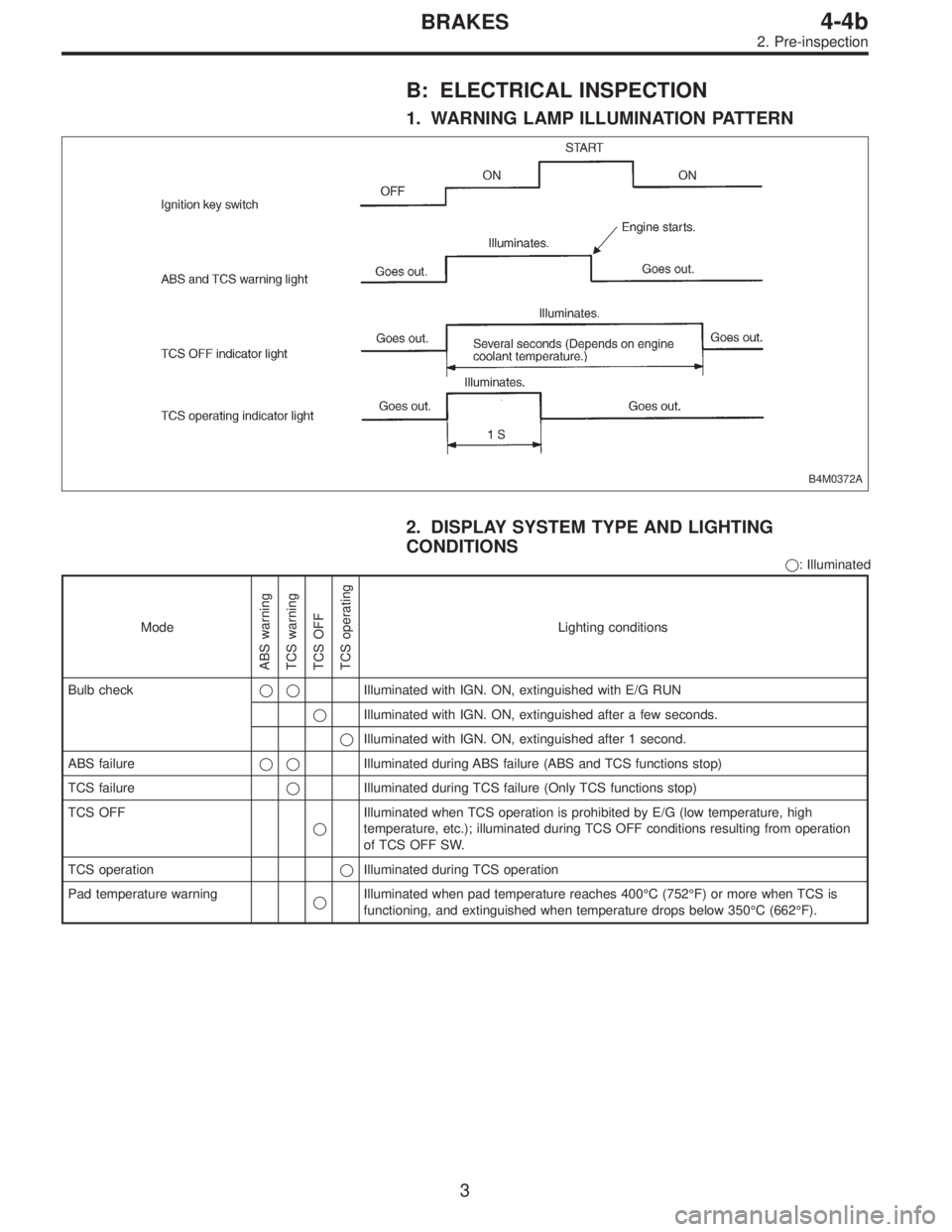
B: ELECTRICAL INSPECTION
1. WARNING LAMP ILLUMINATION PATTERN
B4M0372A
2. DISPLAY SYSTEM TYPE AND LIGHTING
CONDITIONS
�: Illuminated
Mode
ABS warning
TCS warning
TCS OFF
TCS operating
Lighting conditions
Bulb check��Illuminated with IGN. ON, extinguished with E/G RUN
�Illuminated with IGN. ON, extinguished after a few seconds.
�Illuminated with IGN. ON, extinguished after 1 second.
ABS failure��Illuminated during ABS failure (ABS and TCS functions stop)
TCS failure�Illuminated during TCS failure (Only TCS functions stop)
TCS OFF
�Illuminated when TCS operation is prohibited by E/G (low temperature, high
temperature, etc.); illuminated during TCS OFF conditions resulting from operation
of TCS OFF SW.
TCS operation�Illuminated during TCS operation
Pad temperature warning
�Illuminated when pad temperature reaches 400°C (752°F) or more when TCS is
functioning, and extinguished when temperature drops below 350°C (662°F).
3
4-4bBRAKES
2. Pre-inspection
Page 2221 of 2890

3. LIST OF ABS/TCS ON-BOARD DIAGNOSTICS
FUNCTIONS
Trouble codeDiagnostic items
Detection timingIndicator
light ON
Parts concerned
At initial checking
Under no control
Under ABS control
Under TCS control
In diagnostic mode
ABS warning light
TCS warning light
TCS OFF indicator light
21 FR
23 FL
25 RR
27 RLDetection of fault in ABS sensor hardware
���� ��—ABS sensor (ABS/TCS C/M)
22 FR
24 FL
26 RR
28 RLDetection of fault in ABS sensor software
��� ��—ABS sensor (ABS/TCS C/M)
��� ��—ABS sensor harness circuit (ABS/TCS C/M)
Detection of fault in ABS sensor software
���—ABS sensor and solenoid valve (ABS/TCS C/M)
���—ABS sensor (ABS/TCS C/M)
Detection of fault in sensor software
���� ��—ABS sensor (ABS/TCS C/M)
31 FRI
32 FRO
33 FLI
34 FLO
35 RRI
36 RRO
37 RLI
38 RLO
61 TCS1
62 TCS2Abnormal valve
����*
���—Solenoid valve (ABS/TCS C/M)
41 Abnormal ABS/TCS C/M
���� ��—ABS/TCS C/M
42 Abnormal line voltage
�������—Power source operating environment (ABS/TCS C/M)
—Power source voltage drop
���� ��—
������—
*: Except when trouble code is being displayed.
10
4-4bBRAKES
5. Control Module I/O Signal
Page 2269 of 2890
B4M0433
B4M0727A
1. CHECK COMMUNICATION CABLES.
1) Operate the TCS sequence control.
2) Measure the voltage between ABS/TCS control module
and the body during the TCS check sequence operation.
Connector & terminal:
(P6) No. 12—body (AET communication cable)
(P6) No. 5—body (AEB communication cable)
(P6) No. 14—body (AEC communication cable)
Specified voltage:
High voltage: 4—5.4 V
Low voltage:2Vorless
Check that each of the above voltage reading
are displayed.
58
4-4bBRAKES
8. Diagnostics Chart with Trouble Code
Page 2296 of 2890

Function code
Measuring
itemsConte")
G2M0096
9. Select Monitor Function Mode
Applicable cartridge of select monitor: No. 498349601
A: LIST OF FUNCTION MODE
1. F MODE (ROM ID, ANALOG DATA ARE
DISPLAYED.)
Function code
Measuring
itemsContents to be monitored Scroll Ref. to 4-4b
Code Abbreviation
F00 ROMECM identifi-
cationROM ID number of ECM is read and enabled com-
munication state is displayed.Possible [T9B0]
F01 FRFR wheel
speed (mile/h)Wheel speed detected by the FR wheel speed sen-
sor is displayed in mile/h.Possible [T9C0]
F02 FLFL wheel
speed (mile/h)Wheel speed detected by the FL wheel speed sen-
sor is displayed in mile/h.Possible [T9D0]
F03 RRRR wheel
speed (mile/h)Wheel speed detected by the RR wheel speed sen-
sor is displayed in mile/h.Possible [T9E0]
F04 RLRL wheel
speed (mile/h)Wheel speed detected by the RL wheel speed sen-
sor is displayed in mile/h.Possible [T9F0]
F05 FRFR wheel
speed (km/h)Wheel speed detected by the FR wheel speed sen-
sor is displayed in km/h.Possible [T9C0]
F06 FLFL wheel
speed (km/h)Wheel speed detected by the FL wheel speed sen-
sor is displayed in km/h.Possible [T9D0]
F07 RRRR wheel
speed (km/h)Wheel speed detected by the RR wheel speed sen-
sor is displayed in km/h.Possible [T9E0]
F08 RLRL wheel
speed (km/h)Wheel speed detected by the RL wheel speed sen-
sor is displayed in km/h.Possible [T9F0]
F09 PSSPedal stroke
sensor outputThe number of output steps of the pedal stroke
sensor is displayed.Possible[T9G0]
85
4-4bBRAKES
9. Select Monitor Function Mode
Page 2297 of 2890

If the system is in normal condition with the engine run at
idle speed (when the brake pedal is off), the LED of EC
(AEC signal) of FA2 will come on, the LED of")
2. FA MODE (ON/OFF DATA ARE DISPLAYED.)
If the system is in normal condition with the engine run at
idle speed (when the brake pedal is off), the LED of EC
(AEC signal) of FA2 will come on, the LED of EM (EAM
signal) blink and all other LED’s go out.
Function code
Measuring
itemsContents to be monitored Scroll Ref. to 4-4b
Code Abbreviation
FA 0OF OFF.SW LED 1 comes on with the OFF switch on.
Possible [T9H0] B1Stop light
switchLED 2 comes on with the switch on (with the brake
pedal down).
VRValve relay
signalLED 3 comes on with the valve relay off.
VMValve relay
monitorLED 4 comes on with the valve relay off.
MRMotor relay
signalLED 5 comes on with the motor on.
MS Motor sensor LED 6 comes on with the motor on.
FSFluid level
sensorLED 7 comes on with the sensor on (the fluid level
is lowered).
FA 1FI FR.IN valveLED 1 comes on when the FR.IN valve is operat-
ing.
Possible [T9I0] RO FR.OUT valveLED 2 comes on when the FR.OUT valve is operat-
ing.
FL FL.IN valve LED 3 comes on when the FL.IN valve is operating.
LO FL.OUT valveLED 4 comes on when the FL.OUT valve is operat-
ing.
T1 TCS1 valve LED 5 comes on when the TCS1 valve is operating.
RI RR.IN valveLED 6 comes on when the RR.IN valve is operat-
ing.
RO RR.OUT valveLED 7 comes on when the RR.OUT valve is operat-
ing.
RI RL.IN valve LED 8 comes on when the RL.IN valve is operating.
LO RL.OUT valveLED 9 comes on when the RL.OUT valve is operat-
ing.
T2 TCS2 valveLED 10 comes on when the TCS2 valve is operat-
ing.
FA 2AWABS warning
lightLED 1 comes on when the warning light is on.
Possible [T9J0] TWTCS warning
lightLED 2 comes on when the warning light is on.
TOTCS OFF
indicator lightLED 3 comes on when the indicator light is on.
TITCS operation
indicator lightLED 4 comes on when the indicator light is on.
EC AEC signalWith the engine run at idle speed, LED 6 (AEC)
comes on and LED 7 (AEB) goes out (They go on
and off depending on the behavior of a vehicle.) EB AEB signal
ET AET signal LED 8 comes on with the TCS control on.
EM EAM signalLED 9 comes on or blinks when the engine control
is enabled.
AT AAT signal LED 10 comes on when ABS control is on.
86
4-4bBRAKES
9. Select Monitor Function Mode

1. Communication failure
(No communication method can be con")
![SUBARU LEGACY 1996 Service Repair Manual B4M0433
B4M0727A
1. CHECK COMMUNICATION CABLES.
1) Operate the TCS sequence control.
<Ref. to 4-4 [W20F0].>
2) Measure the voltage between ABS/TCS control module
and the body during the TCS check sequ](/manual-img/17/57433/w960_57433-2268.png "SUBARU LEGACY 1996 Service Repair Manual B4M0433
B4M0727A
1. CHECK COMMUNICATION CABLES.
1) Operate the TCS sequence control.
<Ref. to 4-4 [W20F0].>
2) Measure the voltage between ABS/TCS control module
and the body during the TCS check sequ")