Page 2126 of 2890
OBD0538
BR: DTC P1502
—RADIATOR FAN FUNCTION PROBLEM
(FAN
—F)—
DTC DETECTING CONDITION:
�Two consecutive trips with fault
TROUBLE SYMPTOM:
�Occurrence of noise
�Overheating
10BR1Check any other DTC (beside DTC P1502) on
display.
CAUTION:
After repair or replacement of faulty parts, conduct
CLEAR MEMORY and INSPECTION MODES.
NOTE:
If the vehicle, with the engine idling, is placed very close to
a wall or another vehicle, preventing normal cooling
function, the OBD system may detect malfunction.
358
2-7ON-BOARD DIAGNOSTICS II SYSTEM
10. Diagnostics Chart with Trouble Code
Page 2128 of 2890
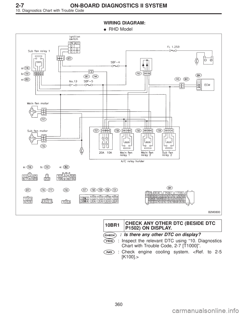
WIRING DIAGRAM:
�RHD Model
B2M0800
10BR1CHECK ANY OTHER DTC (BESIDE DTC
P1502) ON DISPLAY.
: Is there any other DTC on display?
: Inspect the relevant DTC using“10. Diagnostics
Chart with Trouble Code, 2-7 [T1000]”.
: Check engine cooling system.
[K100].>
360
2-7ON-BOARD DIAGNOSTICS II SYSTEM
10. Diagnostics Chart with Trouble Code
Page 2129 of 2890
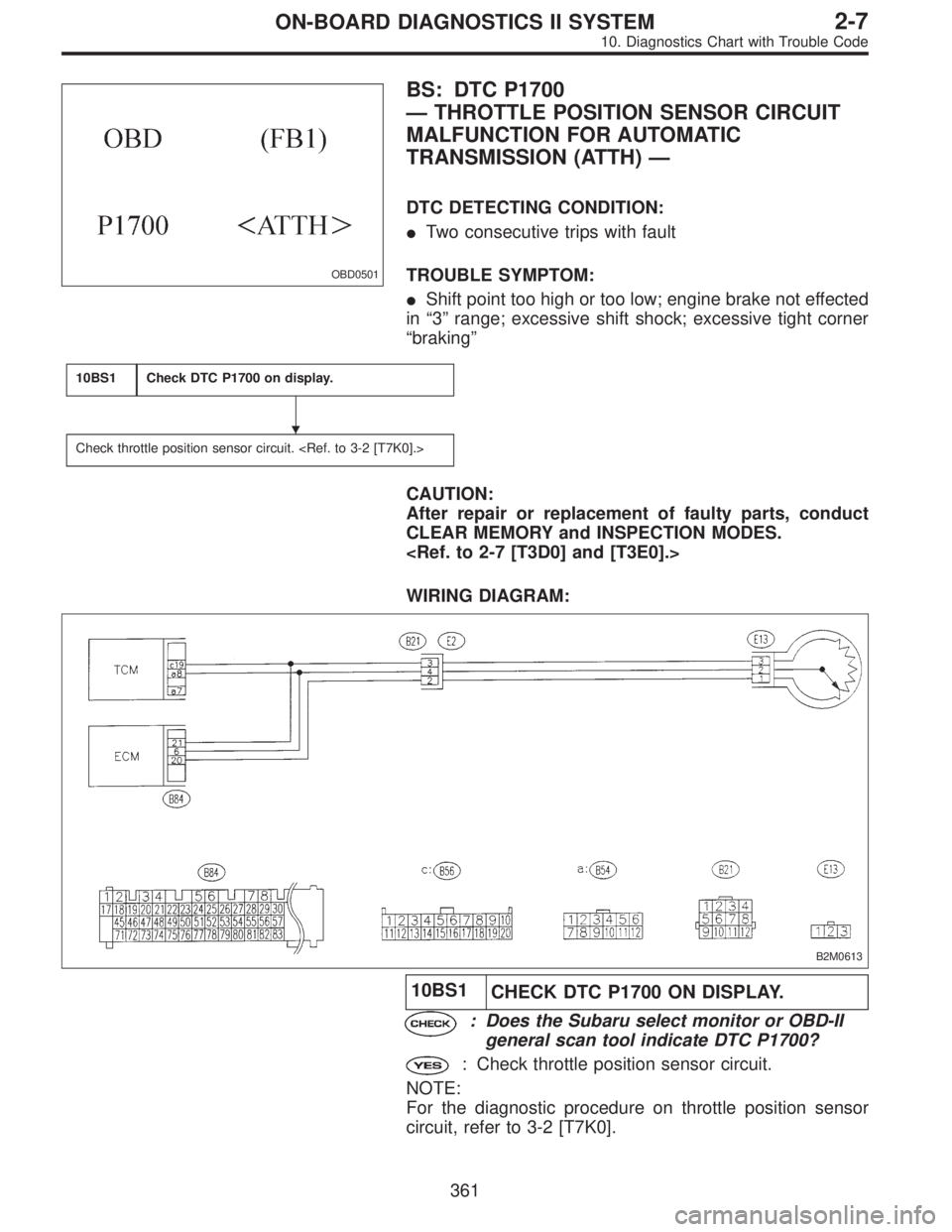
OBD0501
BS: DTC P1700
—THROTTLE POSITION SENSOR CIRCUIT
MALFUNCTION FOR AUTOMATIC
TRANSMISSION (ATTH)—
DTC DETECTING CONDITION:
�Two consecutive trips with fault
TROUBLE SYMPTOM:
�Shift point too high or too low; engine brake not effected
in“3”range; excessive shift shock; excessive tight corner
“braking”
10BS1Check DTC P1700 on display.
Check throttle position sensor circuit.
CAUTION:
After repair or replacement of faulty parts, conduct
CLEAR MEMORY and INSPECTION MODES.
WIRING DIAGRAM:
B2M0613
10BS1
CHECK DTC P1700 ON DISPLAY.
: Does the Subaru select monitor or OBD-II
general scan tool indicate DTC P1700?
: Check throttle position sensor circuit.
NOTE:
For the diagnostic procedure on throttle position sensor
circuit, refer to 3-2 [T7K0].
�
361
2-7ON-BOARD DIAGNOSTICS II SYSTEM
10. Diagnostics Chart with Trouble Code
Page 2136 of 2890
B2M0947
BV: DTC P0461
—FUEL LEVEL SENSOR CIRCUIT RANGE/
PERFORMANCE PROBLEM (EXERR22)—
DTC DETECTING CONDITION:
�Two consecutive trips with fault
10BV1Check DTC P1402 on display.
CAUTION:
After repair or replacement of faulty parts, conduct
CLEAR MEMORY and INSPECTION MODES.
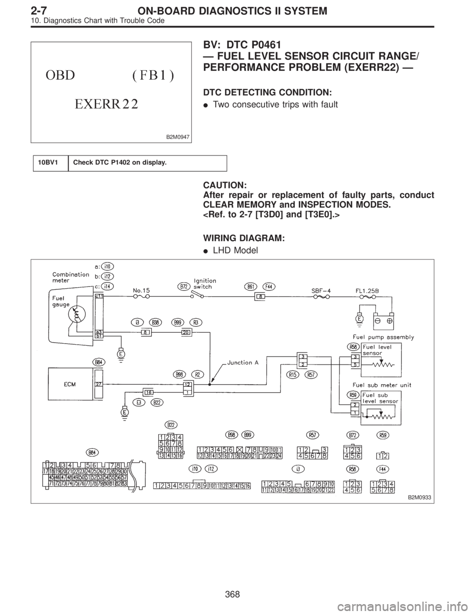
WIRING DIAGRAM:
�LHD Model
B2M0933
368
2-7ON-BOARD DIAGNOSTICS II SYSTEM
10. Diagnostics Chart with Trouble Code
Page 2137 of 2890
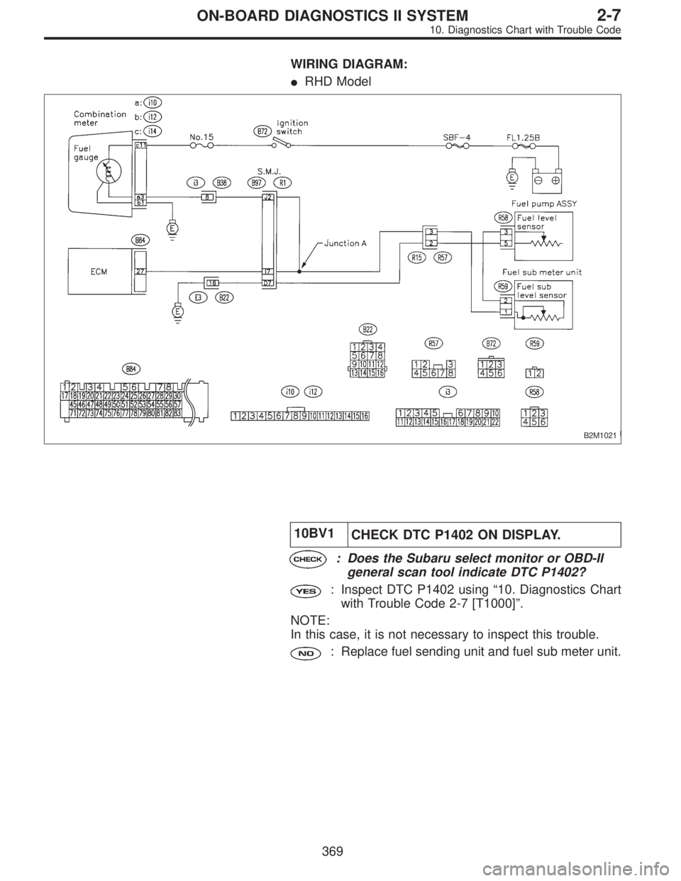
WIRING DIAGRAM:
�RHD Model
B2M1021
10BV1
CHECK DTC P1402 ON DISPLAY.
: Does the Subaru select monitor or OBD-II
general scan tool indicate DTC P1402?
: Inspect DTC P1402 using“10. Diagnostics Chart
with Trouble Code 2-7 [T1000]”.
NOTE:
In this case, it is not necessary to inspect this trouble.
: Replace fuel sending unit and fuel sub meter unit.
369
2-7ON-BOARD DIAGNOSTICS II SYSTEM
10. Diagnostics Chart with Trouble Code
Page 2151 of 2890
B: ABNORMAL DISPLAY ON AT OIL TEMP
INDICATOR
When any on-board diagnostic item is malfunctioning, the
display on the AT OIL TEMP indicator blinks immediately
after the engine starts.
The malfunctioning part or unit can be determined by a
trouble code during on-board diagnostic operation. Prob-
lems which occurred previously can also be identified
through the memory function.
If the AT OIL TEMP indicator does not show a problem
(although a problem is occurring), the problem can be
determined by checking the performance characteristics of
each sensor using the select monitor.
Indicator signal is as shown in the figure.
WARNING:
Warning can be noticed only when the engine is ini-
tially started.
B3M0410A
11
3-2AUTOMATIC TRANSMISSION AND DIFFERENTIAL
6. Diagnostic Chart for On-board Diagnostic System
Page 2154 of 2890
 indicates a“ten”, and the
short se")
2. HOW TO READ TROUBLE CODE OF INDICATOR
LIGHT
The AT OIL TEMP indicator light flashes the code corre-
sponding to the faulty part.
The long segment (1.2 sec on) indicates a“ten”, and the
short segment (0.2 sec on) signifies a“one”.
B3M0193A
E: CLEAR MEMORY
Current trouble codes shown on the display are cleared by
turning the ignition switch OFF after conducting on-board
diagnostic operation. Previous trouble codes, however,
cannot be cleared since they are stored in the TCM
memory which is operating on the back-up power supply.
These trouble codes can be cleared by removing the speci-
fied fuse (located under the right lower portion of the instru-
ment panel).
CLEAR MEMORY:
Removal of No. 14 fuse (for at least one minute)
�The No. 14 fuse is located in the line to the memory
back-up power supply of the TCM and ABS/TCS control
module. Removal of this fuse clears the previous trouble
codes stored in the TCM and ABS/TCS control module
memory.
�Be sure to remove the No. 14 fuse for at least the speci-
fied length of time. Otherwise, trouble codes may not be
cleared.
14
3-2AUTOMATIC TRANSMISSION AND DIFFERENTIAL
6. Diagnostic Chart for On-board Diagnostic System
Page 2194 of 2890
 56
F01 Battery voltage VB V Battery voltage")
B: LIST OF OUTPUT MODES
1. FUNCTION MODE
Mode Contents Abbr. Unit Contents of display Page
F00 Mode display——AT or EGI mode (when monitor is connected.) 56
F01 Battery voltage VB V Battery voltage applied to control unit. 56
F02 Vehicle speed sensor 1 VSP1 m/h Vehicle speed (miles/h) sent from vehicle speed sensor 1. 57
F03 Vehicle speed sensor 1 VSP1 km/h Vehicle speed (km/h) sent from vehicle speed sensor 1. 57
F04 Vehicle speed sensor 2 VSP2 m/h Vehicle speed (miles/h) sent from vehicle speed sensor 2. 57
F05 Vehicle speed sensor 2 VSP2 km/h Vehicle speed (km/h) sent from vehicle speed sensor 2. 57
F06 Engine speed EREV rpm Engine speed sent from ECM. 58
F07 ATF temperature sensor ATFT°F ATF temperature (°F) sent from ATF temperature sensor. 58
F08 ATF temperature sensor ATFT°C ATF temperature (°C) sent from ATF temperature sensor. 58
F09 Throttle position sensor THV V Voltage sent from throttle position sensor. 59
F10 Gear position GEAR—Transmission gear position 59
F11 Line pressure duty PLDTY % Duty ratio flowing through duty solenoid A. 60
F12 Lock-up duty LUDTY % Duty ratio flowing through duty solenoid B. 61
F13 AWD duty 4WDTY % Duty ratio flowing through duty solenoid C. 62
F14Throttle position sensor
power supplyTHVCC V Power supply voltage to throttle position sensor 63
F15 Mass air flow signal AFM V Output voltage from air flow sensor 63
54
3-2AUTOMATIC TRANSMISSION AND DIFFERENTIAL
8. Diagnostic Chart with Select Monitor