Page 1889 of 2890

Problem parts
Inhibitor switch
Control module
Vehicle speed sensor 1
Vehicle speed sensor 2
Select cable
Select lever
FWD switch
Starter motor and harness
Throttle position sensor
Hold switch
Accumulator (“N”—“D”)
Accumulator (2A)
Accumulator (4A)
Accumulator (3R)
ATF temperature sensor
Strainer
Duty solenoid A
Duty solenoid B
Shift solenoid 1
Shift solenoid 2
Shift solenoid 3
Control valve
Detent spring
Manual plate
Transfer clutch
Transfer valve
Transfer pipe
Duty solenoid C
Forward clutch
Symptom1234567891011121314151617181920212223242526272829
Engine brake is not effected when select
lever is in“3”or“2”range.
Engine brake is not effected when select
lever is in“1”range.�
Shift characteristics are erroneous.���� � �
No lock-up occurs.����
Vehicle cannot be set in“D”range power
mode.��
“D”range power mode cannot be released.���
Parking brake is not effected.��
Shift lever cannot be moved or is hard to
move from“P”range.��
Select lever is hard to move.�� ��
Select lever is too light to move (unreason-
able resistance).��
ATF spurts out.
Differential oil spurts out.
Differential oil level changes excessively.
Odor is produced from oil supply pipe.��
Shock occurs when select lever is moved
from“1”to“2”range.� ���� �
Slippage occurs when select lever is moved
from“1”to“2”range.� ���� �
Shock occurs when select lever is moved
from“2”to“3”range.������
Slippage occurs when select lever is moved
from“2”to“3”range.������
Shock occurs when select lever is moved
from“3”to“4”range.� � ��� �
Slippage occurs when select lever is moved
from“3”to“4”range.� � ��� �
Shock occurs when select lever is moved
from“3”to“2”range.�����
Shock occurs when select lever is moved
from“D”to“1”range.�����
Shock occurs when select lever is moved
from“2”to“1”range.�����
Shock occurs when accelerator pedal is
released at medium speeds.�����
Vibration occurs during straight-forward
operation.��
Select lever slips out of position during
acceleration or while driving on rough terrain.�� ��
Vibration occurs during turns (tight corner
“braking”phenomenon).��� �� � �� �
Front wheel slippage occurs during standing
starts.� � � �� � � ����
Vehicle is not set in FWD mode.�� ���
1234567891011121314151617181920212223242526272829
121
2-7ON-BOARD DIAGNOSTICS II SYSTEM
9. General Diagnostics Table
Page 1890 of 2890

One-way clutch (3-")
Overrunning clutch
Drive pinion
Crown gear
Axle shaft
Differential gear
Final gear
Seal pipe
Oil pump
High clutch
Band brake
Low & reverse clutch
Reverse clutch
One-way clutch (1-2)
One-way clutch (3-4)
Double oil seal
Input shaft
Output shaft
Planetary gear
Reduction gear
Drive plate
Torque converter one-way clutch
Lock-up facing
Lock-up damper
ATF deterioration
ATF level too high or too low
Differential gear oil level too high or too low
Engine performance
Engine speed signal
Parking brake mechanism
Problem parts
30 31 32 33 34 35 36 37 38 39 40 41 42 43 44 45 46 47 48 49 50 51 52 53 54 55 56 57 58 Symptom
�Engine brake is not effected when select
lever is in“3”or“2”range.
�Engine brake is not effected when select
lever is in“1”range.
Shift characteristics are erroneous.
��No lock-up occurs.
Vehicle cannot be set in“D”range power
mode.
“D”range power mode cannot be released.
�Parking brake is not effected.
�Shift lever cannot be moved or is hard to
move from“P”range.
Select lever is hard to move.
Select lever is too light to move (unreason-
able resistance).
�ATF spurts out.
�Differential oil spurts out.
��Differential oil level changes excessively.
� ���� � �Odor is produced from oil supply pipe.
���Shock occurs when select lever is moved
from“1”to“2”range.
�Slippage occurs when select lever is moved
from“1”to“2”range.
�� � �Shock occurs when select lever is moved
from“2”to“3”range.
��Slippage occurs when select lever is moved
from“2”to“3”range.
�� ��Shock occurs when select lever is moved
from“3”to“4”range.
�Slippage occurs when select lever is moved
from“3”to“4”range.
�� �Shock occurs when select lever is moved
from“3”to“2”range.
�Shock occurs when select lever is moved
from“D”to“1”range.
��Shock occurs when select lever is moved
from“2”to“1”range.
��Shock occurs when accelerator pedal is
released at medium speeds.
��Vibration occurs during straight-forward
operation.
Select lever slips out of position during
acceleration or while driving on rough terrain.
�Vibration occurs during turns (tight corner
“braking”phenomenon).
Front wheel slippage occurs during standing
starts.
Vehicle is not set in FWD mode.
30 31 32 33 34 35 36 37 38 39 40 41 42 43 44 45 46 47 48 49 50 51 52 53 54 55 56 57 58
122
2-7ON-BOARD DIAGNOSTICS II SYSTEM
9. General Diagnostics Table
Page 2140 of 2890
1. Supplemental Restraint System
“Airbag”
Airbag system wiring harness is routed near the transmis-
sion control module (TCM).
�All Airbag system wiring harness and connectors
are colored yellow. Do not use electrical test equip-
ment on these circuit.
�Be careful not to damage Airbag system wiring har-
ness when performing diagnostics and servicing the
TCM.
B3M0173A
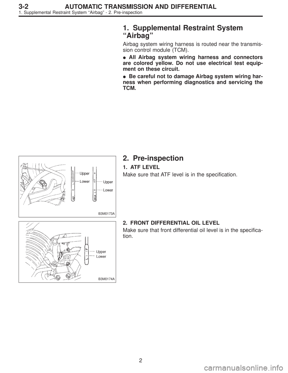
2. Pre-inspection
1. ATF LEVEL
Make sure that ATF level is in the specification.
B3M0174A
2. FRONT DIFFERENTIAL OIL LEVEL
Make sure that front differential oil level is in the specifica-
tion.
2
3-2AUTOMATIC TRANSMISSION AND DIFFERENTIAL
1. Supplemental Restraint System“Airbag”- 2. Pre-inspection
Page 2141 of 2890
1. Supplemental Restraint System
“Airbag”
Airbag system wiring harness is routed near the transmis-
sion control module (TCM).
�All Airbag system wiring harness and connectors
are colored yellow. Do not use electrical test equip-
ment on these circuit.
�Be careful not to damage Airbag system wiring har-
ness when performing diagnostics and servicing the
TCM.
B3M0173A
2. Pre-inspection
1. ATF LEVEL
Make sure that ATF level is in the specification.
B3M0174A
2. FRONT DIFFERENTIAL OIL LEVEL
Make sure that front differential oil level is in the specifica-
tion.
2
3-2AUTOMATIC TRANSMISSION AND DIFFERENTIAL
1. Supplemental Restraint System“Airbag”- 2. Pre-inspection
Page 2142 of 2890
 Check that selector lever does not move from“N”to“R”
without pushing the bu")
G3M0717
3. OPERATION OF SHIFT SELECTOR LEVER
WARNING:
Stop the engine while checking operation of selector
lever.
1) Check that selector lever does not move from“N”to“R”
without pushing the button.
2) Check that selector lever does not move from“R”to“P”
without pushing the button.
3) Check that selector lever does not move from“P”to“R”
without pushing the button.
4) Check that selector lever does not move from“3”to“2”
without pushing the button.
3. Electrical Components Location
1. SENSOR AND CONTROL MODULE
B3M0178B
�1Throttle position sensor
�
2Dropping resistor
�
3Vehicle speed sensor 2
�
4Inhibitor switch
�
5ECM
�
6Vehicle speed sensor 1 (AWD)
�
7Vehicle speed sensor 1 (FWD)
�
8TCM�
9Data link connector (for Subaru select monitor only)
�
10Data link connector (for Subaru select monitor and OBD-II
general scan tool)
�
11Diagnosis connector
�
12Diagnosis terminal
�
13AT OIL TEMP indicator light
(AT diagnostic indicator light)
3
3-2AUTOMATIC TRANSMISSION AND DIFFERENTIAL
2. Pre-inspection - 3. Electrical Components Location
Page 2143 of 2890
 Check that selector lever does not move from“N”to“R”
without pushing the bu")
G3M0717
3. OPERATION OF SHIFT SELECTOR LEVER
WARNING:
Stop the engine while checking operation of selector
lever.
1) Check that selector lever does not move from“N”to“R”
without pushing the button.
2) Check that selector lever does not move from“R”to“P”
without pushing the button.
3) Check that selector lever does not move from“P”to“R”
without pushing the button.
4) Check that selector lever does not move from“3”to“2”
without pushing the button.
3. Electrical Components Location
1. SENSOR AND CONTROL MODULE
B3M0178B
�1Throttle position sensor
�
2Dropping resistor
�
3Vehicle speed sensor 2
�
4Inhibitor switch
�
5ECM
�
6Vehicle speed sensor 1 (AWD)
�
7Vehicle speed sensor 1 (FWD)
�
8TCM�
9Data link connector (for Subaru select monitor only)
�
10Data link connector (for Subaru select monitor and OBD-II
general scan tool)
�
11Diagnosis connector
�
12Diagnosis terminal
�
13AT OIL TEMP indicator light
(AT diagnostic indicator light)
3
3-2AUTOMATIC TRANSMISSION AND DIFFERENTIAL
2. Pre-inspection - 3. Electrical Components Location
Page 2144 of 2890
B2M0155AOBD0046A
B2M0211AB3M0182A
B3M0183AB3M0184A
B3M0185AB3M0443D
4
3-2AUTOMATIC TRANSMISSION AND DIFFERENTIAL
3. Electrical Components Location
Page 2145 of 2890
OBD0005COBD0006A
H3M1161AOBD0008D
5
3-2AUTOMATIC TRANSMISSION AND DIFFERENTIAL
3. Electrical Components Location