Page 1281 of 2890
�Be careful to prevent foreign particles from getting into
hydraulic unit.
�When a new hydraulic unit is installed, apply a coat of
rust-preventive wax (Nippeco LT or GB) to bracket attach-
ing bolts after tightening.
�Do not pull harness disconnecting harness connector.
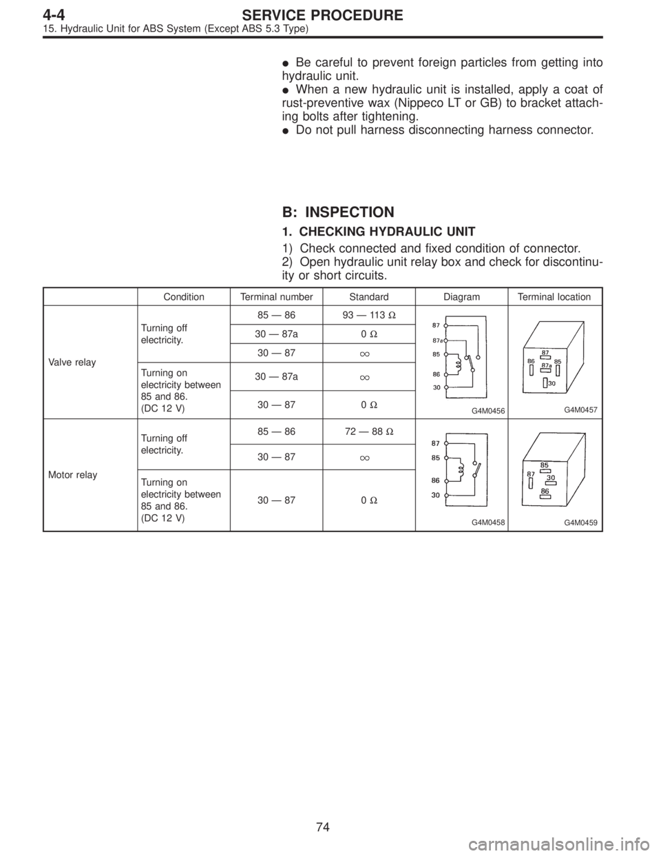
B: INSPECTION
1. CHECKING HYDRAULIC UNIT
1) Check connected and fixed condition of connector.
2) Open hydraulic unit relay box and check for discontinu-
ity or short circuits.
Condition Terminal number Standard Diagram Terminal location
Valve relayTurning off
electricity.85—86 93—11 3Ω
G4M0456G4M0457
30—87a 0Ω
30—87
Turning on
electricity between
85 and 86.
(DC 12 V)30—87a
30—87 0Ω
Motor relayTurning off
electricity.85—86 72—88Ω
G4M0458G4M0459
30—87
Turning on
electricity between
85 and 86.
(DC 12 V)30—87 0Ω
74
4-4SERVICE PROCEDURE
15. Hydraulic Unit for ABS System (Except ABS 5.3 Type)
Page 1303 of 2890
 Remove bolts which secure hydraulic unit bracket, and
remove hydraulic unit from engine compartment.
CAUTION:
�Hydraulic unit cannot be disassembled. Do not
attempt to loosen bolts and nuts")
B4M0628
5) Remove bolts which secure hydraulic unit bracket, and
remove hydraulic unit from engine compartment.
CAUTION:
�Hydraulic unit cannot be disassembled. Do not
attempt to loosen bolts and nuts.
�Do not drop or bump hydraulic unit.
�Do not turn the hydraulic unit upside down or place
it on its side.
�Be careful to prevent foreign particles from getting
into hydraulic unit.
�Do not pull harness disconnecting harness connec-
tor.
B: INSPECTION
1) Check connected and fixed condition of connector.
2) Check for discontinuity or short circuits.
Condition Terminal number Standard Diagram Terminal location
Valve relayTurning off
electricity.A—B90Ω
B4M0629A
B4M0630
C—F0Ω
C—E
Turning on
electricity between
A and B.
(DC 12 V)C—F
C—E0Ω
Motor relayTurning off
electricity.a—b* 57Ω
B4M0631AB4M0632
c—d
Turning on
electricity between
a and b.
(DC 12 V)c—d0Ω
*: Attach circuit tester positive probe to terminal“a”and its negative probe to terminal“b”and measure the circuit resistance.
94
4-4SERVICE PROCEDURE
20. Hydraulic Unit for ABS/TCS System
Page 1321 of 2890
 Check connected and fixed condition of connector.
2) Check valve relay and motor relay for discontinuity or
short circuits.
Condition Terminal number Standard Diagram Terminal locatio")
B: INSPECTION
1) Check connected and fixed condition of connector.
2) Check valve relay and motor relay for discontinuity or
short circuits.
Condition Terminal number Standard Diagram Terminal location
Valve relayTurning off
electricity.85—86 103±10Ω
G4M0456G4M0457
30—87a less than 0.5Ω
30—87 more than 1 MΩ
Turning on
electricity between
85 and 86.
(DC 12 V)30—87a more than 1 MΩ
30—87 less than 0.5Ω
Motor relayTurning off
electricity.85—86 80±8Ω
G4M0458G4M0459
30—87 more than 1 MΩ
Turning on
electricity between
85 and 86.
(DC 12 V)30—87 less than 0.5Ω
C: CHECKING THE HYDRAULIC UNIT ABS
OPERATION
1. CHECKING THE HYDRAULIC UNIT ABS
OPERATION BY PRESSURE GAUGE
1) Lift-up vehicle and remove wheels.
2) Disconnect the air bleeder screws from the FL and FR
caliper bodies.
B4M0633A
3) Connect two pressure gauges to the FL and FR caliper
bodies.
CAUTION:
�Pressure gauges used exclusively for brake fluid
must be used.
�Do not employ pressure gauge previously used for
transmission since the piston seal is expanded which
may lead to malfunction of the brake.
NOTE:
Wrap sealing tape around the pressure gauge.
111
4-4SERVICE PROCEDURE
22. Hydraulic Unit for ABS System (ABS 5.3 Type)
Page 1634 of 2890
B6M0489A
1) Diodes on“+”side
Continuity of proper diodes on“+”side
BAT side
(+) (�)
Terminal
N, U, V and W
(+)—Continuity must
not exist.
(�)Continuity
must exist.—
B6M0490A
2) Diodes on“�”side
Continuity of proper diodes on“�”side
“E”side
(+) (�)
Terminal
N, U, V and W
(+)—Continuity must
exist.
(�)Continuity
must not exist.—
CAUTION:
Never use a high tension insulation tester, such as a
meggar as it will damage diodes with its high tension.
B6M0491A
5. IC REGULATOR
1) Compose a circuit diagram as shown in figure.
�
1Voltage meter: 0 to 30 V
�
2Switch 1
�
3Variable DC power supply: Variable 0 to 20 V, 1 A or
more
�
4Lamp 2
�
5Lamp 1
�
6Switch 3
�
7Switch 2
�
8Plus generator: Power supply 5 to 30 V, 1 kHz
20
6-1SERVICE PROCEDURE
2. Generator
Page 1716 of 2890

B6M0361A
22. Security System
A: REMOVAL AND INSTALLATION
1. STARTER INTERRUPT RELAY
NOTE:
The starter interrupt relay and headlight alarm relay use the
same parts and are mounted parallel to each other.
Therefore, before removal and installation, identify the
starter interrupt relay by the color of its wiring connection.
1) Remove instrument panel lower cover.
2) Disconnect connector of starter interrupt relay.
3) Remove starter interrupt relay.
4) Installation is in the reverse order of removal.
B6M0361A
2. HEADLIGHT ALARM RELAY
NOTE:
The headlight alarm relay and starter interrupt relay use the
same parts and are mounted parallel to each other.
Therefore, before removal and installation, identify the
headlight alarm relay by the color of its wiring connection.
1) Remove instrument panel lower cover.
2) Disconnect connector of headlight alarm relay.
3) Remove headlight alarm relay.
4) Installation is in the reverse order of removal.
B6M0363A
3. ENGINE HOOD SWITCH
1) Disconnect connector of engine hood switch from bot-
tom side of switch body.
2) Remove headlight (LH).
3) Remove attaching bolt, and then remove engine hood
switch.
4) Installation is in the reverse order of removal.
52
6-2SERVICE PROCEDURE
22. Security System
Page 1730 of 2890
2. AT Shift Lock System
A: WIRING DIAGRAM
B6M0466
66
6-2DIAGNOSTICS
2. AT Shift Lock System
Page 1847 of 2890
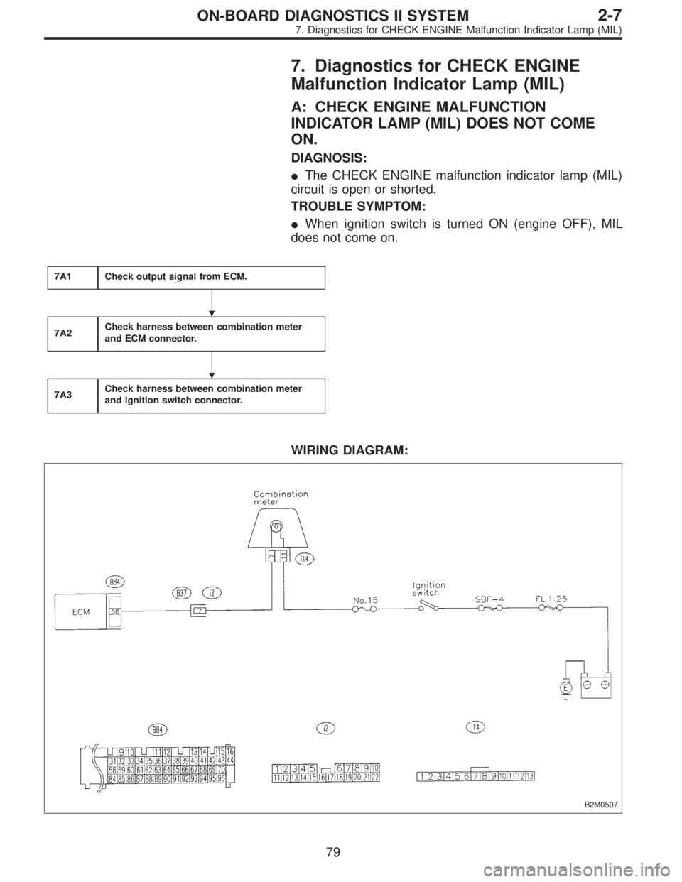
7. Diagnostics for CHECK ENGINE
Malfunction Indicator Lamp (MIL)
A: CHECK ENGINE MALFUNCTION
INDICATOR LAMP (MIL) DOES NOT COME
ON.
DIAGNOSIS:
�The CHECK ENGINE malfunction indicator lamp (MIL)
circuit is open or shorted.
TROUBLE SYMPTOM:
�When ignition switch is turned ON (engine OFF), MIL
does not come on.
7A1Check output signal from ECM.
7A2Check harness between combination meter
and ECM connector.
7A3Check harness between combination meter
and ignition switch connector.
WIRING DIAGRAM:
B2M0507
�
�
79
2-7ON-BOARD DIAGNOSTICS II SYSTEM
7. Diagnostics for CHECK ENGINE Malfunction Indicator Lamp (MIL)
Page 1850 of 2890
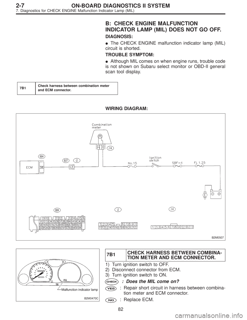
B: CHECK ENGINE MALFUNCTION
INDICATOR LAMP (MIL) DOES NOT GO OFF.
DIAGNOSIS:
�The CHECK ENGINE malfunction indicator lamp (MIL)
circuit is shorted.
TROUBLE SYMPTOM:
�Although MIL comes on when engine runs, trouble code
is not shown on Subaru select monitor or OBD-II general
scan tool display.
7B1Check harness between combination meter
and ECM connector.
WIRING DIAGRAM:
B2M0507
B2M0470C
7B1CHECK HARNESS BETWEEN COMBINA-
TION METER AND ECM CONNECTOR.
1) Turn ignition switch to OFF.
2) Disconnect connector from ECM.
3) Turn ignition switch to ON.
: Does the MIL come on?
: Repair short circuit in harness between combina-
tion meter and ECM connector.
: Replace ECM.
82
2-7ON-BOARD DIAGNOSTICS II SYSTEM
7. Diagnostics for CHECK ENGINE Malfunction Indicator Lamp (MIL)
 Diodes on“+”side
Continuity of proper diodes on“+”side
BAT side
(+) (�)
Terminal
N, U, V and W
(+)—Continuity must
not exist.
(�)Continuity
must exist.—
B6M0490A
2) Diodes on�")