Page 269 of 2890
![SUBARU LEGACY 1996 Service Repair Manual 6-3
[Dso2]
WIRING
DIAGRAM
6
.
Wiring
Diagram
a
:
B54
b
:
BSS
c
:
B56
Transmission
:control
module
853
Shield
joint
connector
Lz7-
E3
822
E2821
-(California
model)
GEB3
Mass
aIr
flow
sensor](/manual-img/17/57433/w960_57433-268.png "SUBARU LEGACY 1996 Service Repair Manual 6-3
[Dso2]
WIRING
DIAGRAM
6
.
Wiring
Diagram
a
:
B54
b
:
BSS
c
:
B56
Transmission
:control
module
853
Shield
joint
connector
Lz7-
E3
822
E2821
-(California
model)
GEB3
Mass
aIr
flow
sensor")
6-3
[Dso2]
WIRING
DIAGRAM
6
.
Wiring
Diagram
a
:
B54
b
:
BSS
c
:
B56
Transmission
:control
module
853
Shield
joint
connector
Lz7-
E3
822
E2821
-(California
model)
GEB3
Mass
aIr
flow
sensor
C
:
i14
il
B36
Comb
i
net
i
on
~?+
BRBR
meter
B76
Test
mode
connector
8l2
Inhibitorswitch
(
&
CD
Transmission
4
Vehicle
l
speed
-
sensor
1
B84
19
Engine
control
module
(
ED
~i
gnitor
B79
~
Chec
k
connector
(
9
)
.
eta
link
connector
S
.
M
.
J
.
[Refer
to
foldout
page
.]
OBD-II
B40
B97
R1
R(5R57
~8
Service
R
,EjeRO
FueI
pump
&
connector
1
-fuel
gauge
module
B76
(GreeN
853B3(G
ray)
Bl3
(Gray)
R58
R57878
(Ye
II
ow)
854
B
lack)
nT
456
4567856789
789012
1234
12345
123456
812
(Gray)
Bll
(Gray)
82l
(L
I
ght
i
14879
(Gray)
822
CL
1
ght
855
(B
I
ac
k)840
(Gray)
gray)
gray)
1234
1234
5678
12345678
7
8
1
9
1
10
1
11
1
124
12345678910111213
8
9
0
l
2
3l4
3l41S16
9
OL31123~ISlb
91001213141516
856
(B
I
ac
k)
i1
B
I
ac
k>
BB4
(L
(
ght
b
I
ue)
12
34
U
56
U
78
UU
9t0
U
1112
U
13141J1
516
1718
1
19
1
20
1
21
1
2223242S
I
26
27282930
3132
1
33
1
34
1
35
1
36
3738
39
40
4142
4344
11
1121314
5
6
78
9
l
01
2
3
456
7
8
9
l0
45
1
46
1
47
1
48
1
49
50
5152
1
53
1
54
1
55
1
56
1
57
1
58
5960
6162
636465
66
6768
64
70
11l2
t
3
(4151617
l8l9
20
l1
1
12
1
l3
1
14
1
15
1
16
1
1
7l8l9
20
2122
7172
7374
75767778
74
B0
8182
3
84
B58687888990
9192
9394
95
96
BUR04-03C
4
Page 270 of 2890

6-3
IDso1a1
WIRING
DIAGRAM
6
.
Wiring
Diagram
R57R15
Combination
meter
To
Power
Supply
Routing
FB-20
MB-3FB-4
ST
FB-22Check
Tachometer
connector
FUSE
Na
15
S8F-2
FUSE
Na
16
[G
519
FUSE
Na
l5
P
v
1-0
B79
CD
:
bm
rI
a
m
~
~
F45
Malfunction
Q
D
:
C
indicator
,
.
862
lamp
7
Speedometer
B
i
circuit
I11
*c~
)
Main
relay
E
o
B47
=
Twisted
wire
=2
R
0
F-0
0-
<
71
846
E
Fuel
pump
relay
"
>-
3z
M
~`
LL
J
C
A
V
mJ
(7
Fue
I
pump
&
~
MM~mVPPP
-+
fuel
gauge
module
~
Jv
Fue
I
S
.
M
.
J
.
mJ
B97
3
Engine
pump
[Refer'
to
a
1,
B17
control
B84
module
foldout
page
.],
JJ
Rl
~/
m
L
C
O
R
Fuel
ix
J
temperature
R67R46
sensor
u
Vehicle
=
speed
'
rr
sensor
D
Fuel
gauge
~
r
Inhibitor
switch
n
R59
Fue
I
gauge
C~
sub
module
R59
R67R68
B17
(B
lack)
12
2
12
C
i14
111213141516171819110111112113
((
9
)
5
1
F1F1
Pressure
Vent
controlcontrol
solenoid
solenoi
valvevalve
R69
OD
846
R47
(Green)
U
:Z~)
123
~
34
13
.
ENGINE
ELECTRICAL
SYSTEM
R47
F-1
Fuel
tank
d
pressure
sensor
(Brown)
M
F1F2-1
'
2
3
[3141
456
1516
(L
I
ght
gray)
i
10
(
2D
(L
i
ght
gray)
12345678910111213(41516
B12
R57B12
(Gray)
1234
12
3
5678
45678
9101112
F45
B79
(Gray)
1
23
45
67
89
IO
1t
12
1314
(2i3
(Brown)
23456789
12345
678910
1111213141516171819201
[t
1
1
12
1
13
1
14
1
15
1
16
1
17
1
18
1
19
1
20
21
1
99
1
BUR10-03A
6
Page 271 of 2890
![SUBARU LEGACY 1996 Service Repair Manual
WIRING
DIAGRAM
[D6013]
6-3
6
.
Wiring
Diagram
Data
link
connector
Testmode
878B75
~
B76
YJ
J
~mm
L
J
)
Ref
.
toAir
/
conditioning
system
.
1
Re
f
.to
Radiator
/
fan
system
.
Ref
.
toAT
control](/manual-img/17/57433/w960_57433-270.png "SUBARU LEGACY 1996 Service Repair Manual
WIRING
DIAGRAM
[D6013]
6-3
6
.
Wiring
Diagram
Data
link
connector
Testmode
878B75
~
B76
YJ
J
~mm
L
J
)
Ref
.
toAir
/
conditioning
system
.
1
Re
f
.to
Radiator
/
fan
system
.
Ref
.
toAT
control")
WIRING
DIAGRAM
[D6013]
6-3
6
.
Wiring
Diagram
Data
link
connector
Testmode
878B75
~
B76
YJ
J
~mm
L
J
)
Ref
.
toAir
/
conditioning
system
.
1
Re
f
.to
Radiator
/
fan
system
.
Ref
.
toAT
control
J
system
.
L
F
d'
3L
a0J
mo
O
~VI~
f~
MP
Enginecontro
I
BB4
module
m
>rCD
J3
3
F
.
.
..
--
~
-
S
'
K
J
'
B19
'-
818
v
--
Bl9
rl
CE
r
......
T5
~
..
....
T6
Front
Pressure
sources
oxygen
switchfr
sensor
~
.,
i
o
.,
.
B75
(Green)
2
B78
(Ye
I
low)
12
34
56789
Rear
oxygen
sensor
(California
model)
876
(Green)
2
Rear
oxygensensor
(Other
models)
Bl
(Brown)
12
818
(De
rk
gray)
21
3
OBD-
11
service
connector
N~
BGO
valve
9
(Gray)
T6
Bl9
21
43
840
(Gray)
B84
(L
1
ght
b
I
ue)
1
2
34
56
78
9l0
llt213141516
1
1
1
2
1
3
1
4
1
5
1
6
1
7
8
t718192021222324252627282930
3132
3334
3S
I
36
1
37
1
38
1
39
1
40
1
41
1
44445464748
49
50
5152
535455565758
59
60
6162
1
63
1
64
1
65
1
66
1
67
1
68
1
6
9
70
1
9
1
10
1
11
1
12
1
13
1
14
1
151671
1
72
1
73
1
74
1
75
1
76
1
77
1
78
1
79
1
80
1
81
1
82
1
83
1
84
85
86
87
88
1
89
1
9
0
1,
192
939495
96
BUR10-03B
a
Page 272 of 2890
6-3
[D6013]
WIRING
DIAGRAM
6
.
Wiring
Diagram
Shield
joint
connector
rE
~
;EB
(
883
E2
B21
Ref
.
toAT
control
system
.
Pressuresensor
....
Englnecontro
I
gg4
module
....
B22
E3
(California
model)
B3
~+~M
B13
Mass
air
Ignitor
flowsensor
(Brown)
E18
E8
(Brown)
(B
I
ack)
B2
E13
(Brown)
12
123
B3
(Grey)
Bl3
(Gray)
12345123456
Ell
(Gray)
123
B21
(L
i
ght
gray)
1234
5678
9
10
ll
l2
Ell
Ignition
coil
883
1234
B22
(L
i
ght
gray)
1
234
S678
9
101112
1
41516
3
fili
BURIO-03C
Eng
i
ne
Throttle
coolant
position
Knock
temperature
E
.
G
.
R
.
sensor
sensor
sensor
solenoid
1
:1
I---I
[--J
[--J
Page 273 of 2890
WIRING
DIAGRAM
[D6013]
6-3
6
.
Wiring
Diagram
CrankshaftCamshaftpositionpositionsensorsensor
P~2
(
E10
I
Ely
3
3
.
.
.
.
.
.
~r------------'
I
~1
r-----------J
ii
i
i
iI
E1
m~
B20
N
I11II
Eng(ne
control
884
module
m
J
Jm
3
~r
H
YJ
J
(D
JJ
CO
;~
E3
N
NJ
?-J
N
3
N
E17
EB
E6
~
E16
-E5
M
N
E7
~N
E4
#4#3
#2
#1
Fuel
Injector
Idle
air
control
Purge
control
solenoid
valve
solenoid
valve
E15
(Darkgray)
(L
(
ght
gray)
E5
Elb
(L
f
ght
gray)
El0
(Gray)
(Dark
gray)
E6
El7
(Darkgray)
1
2
C
I
D
g84
(L
i
ght
b
l
ue)
1234
5678
910
111213141516
E4
(B
I
ue)
E7
(Gre
)
B20
(L
r
ht
171814202122232425262728293045464748495051525354555657
3132333435363738394041424344
58596061626364656667b96970
yg
gra
y)
123
71
1
72
1
73
1
74
1
75
1
767778
79
80
8182
83
84
1
85
1
86
1
87
1
'9
1
89
1
90
1
9192
1
93
1
94
1
959b
12
123
456
BUR10-03D
9
Page 274 of 2890
6-3
[Dso1s]
WIRING
DIAGRAM
6
.
Wiring
Diagram
16
.
FUEL
GAUGE
SYSTEM
To
Power
Supply
Routing
FB-20
FUSE
Na
15
a
:i
10
Combinationmeter
b
:
i12
c
:
i14
Low-fuel
^^
warning
light
Fuel
gauge
(3
B38
Fuel
gauge
sub
module
R59
E
v
J\
B
Fuel
gauge
module
~I
R58
B22
E3
R
E
S
.
M
.
J
.
[Refer
to
foldout
page
.]
R59R57R58
il4
12
3
123
12
45678
456
12345678910111213
B22
(L
i
ght
gray)
(L
i
ght
gray)
Q
l0
i
12
(L
i
ght
gray)
1
2
34
i3
(Brown)
5678
9101112
1
1
1
2
1
3
45
678910
12345678910111213141516
13141516
1
11
1
12
1
13
1
14
1
15
1
16
1
17
1
18
1
19
1
2
11
9
1
1121314E
;11
6
1
7
F8
~9
1
10
1
11
1
12
1
13
1
14
1
15
1
1
-6
1
1311
BUR61-02
10
Page 712 of 2890
")
1. Clutch System
Condition Possible cause and testing Corrective action
1. Clutch slip-
pageIt is hard to perceive clutch slippage in the early stage, but pay attention to the following symptoms.
(a) Engine revs up when shifting.
(b) High speed driving is impossible; especially rapid acceleration impossible and vehicle speed does not increase in
proportion to an increase in engine speed.
(c) Power falls, particularly when ascending a slope, and there is a smell of burning of the clutch facing.
�Method of testing: Put the vehicle in stationary condition with parking brake fully applied. Disengage the clutch and
shift the transmission gear into the first. Gradually allow the clutch to engage while gradually increasing the engine
speed. The clutch function is satisfactory if the engine stalls. However, the clutch is slipping if the vehicle does not
start off and the engine does not stall.
(a) No clutch pedal play Readjust.
(b) No release lever end play Readjust.
(c) Clutch facing smeared by oil Replace.
(d) Worn clutch facing Replace.
(e) Deteriorated diaphragm spring Replace.
(f ) Distorted pressure plate or flywheel Correct or replace.
(g) Defective release bearing holder Correct or replace.
(h) Defective pedal and cable system Correct or replace.
2. Clutch
drags.As a symptom of this trouble, a harsh scratching noise develops and control becomes quite difficult when shifting
gears. The symptom becomes more apparent when shifting into the first gear. However, because much trouble of the
this sort is due to defective synchronization mechanism, carry out the test as described after.
�Method of testing: Refer to DIAGNOSTIC DIAGRAM on page after.
It may be judged as insufficient disengagement of clutch if any noise occurs during this test.
(a) Excessive clutch pedal play Readjust.
(b) Excessive clutch release lever play Readjust.
(c) Worn or rusty clutch disc hub spline Replace clutch disc.
(d) Excessive deflection of clutch disc facing Correct or replace.
(e) Seized crankshaft pilot needle bearing Replace.
(f ) Malfunction of pedal and cable system Correct or replace.
(g) Cracked clutch disc facing Replace.
(h) Sticked clutch disc (smeared by oil or water) Replace.
3. Clutch chat-
ters.Clutch chattering is an unpleasant vibration to the whole body when the vehicle is just started with clutch partially
engaged.
(a) Improper clutch cable routing Correct.
(b) Adhesion of oil on the facing Replace clutch disc.
(c) Weak or broken torsion spring Replace clutch disc.
(d) Defective facing contact or excessive disc Replace clutch disc defection.
(e) Warped pressure plate or flywheel Correct or replace.
(f ) Loose disc rivets Replace clutch disc.
(g) Loose engine mounting Retighten or replace mounting.
(h) Improper adjustment of pitching stopper Adjustment.
11
2-10DIAGNOSTICS
1. Clutch System
Page 714 of 2890
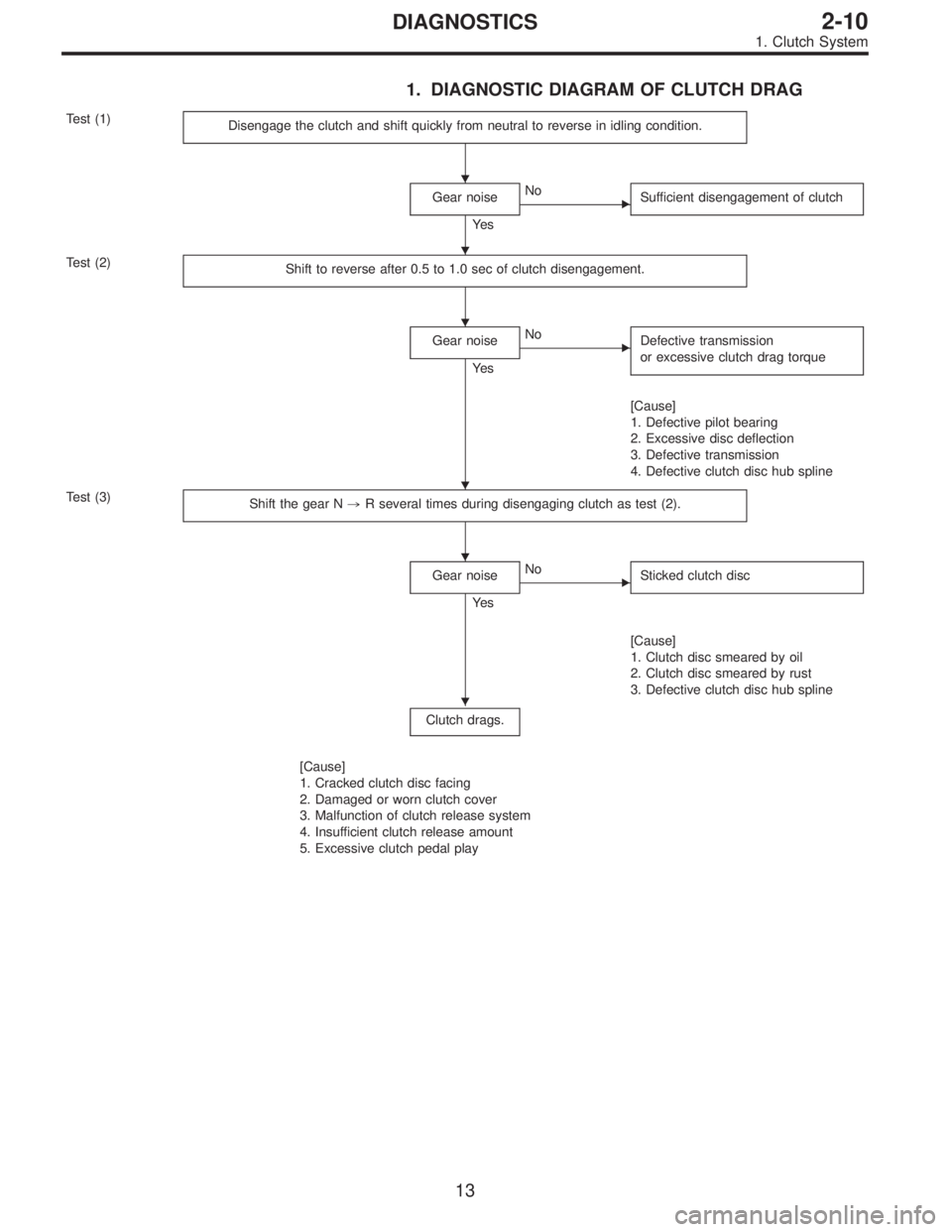
1. DIAGNOSTIC DIAGRAM OF CLUTCH DRAG
Test (1)
Disengage the clutch and shift quickly from neutral to reverse in idling condition.
Gear noise
Ye s
�No
Sufficient disengagement of clutch
Test (2)
Shift to reverse after 0.5 to 1.0 sec of clutch disengagement.
Gear noise
Ye s
�No
Defective transmission
or excessive clutch drag torque
[Cause]
1. Defective pilot bearing
2. Excessive disc deflection
3. Defective transmission
4. Defective clutch disc hub spline
Test (3)
Shift the gear N,R several times during disengaging clutch as test (2).
Gear noise
Ye s
�No
Sticked clutch disc
[Cause]
1. Clutch disc smeared by oil
2. Clutch disc smeared by rust
3. Defective clutch disc hub spline
Clutch drags.
[Cause]
1. Cracked clutch disc facing
2. Damaged or worn clutch cover
3. Malfunction of clutch release system
4. Insufficient clutch release amount
5. Excessive clutch pedal play
�
�
�
�
�
�
13
2-10DIAGNOSTICS
1. Clutch System
![SUBARU LEGACY 1996 Service Repair Manual 6-3
[D6013]
WIRING
DIAGRAM
6
.
Wiring
Diagram
Shield
joint
connector
rE
~
;EB
(
883
E2
B21
Ref
.
toAT
control
system
.
Pressuresensor
....
Englnecontro
I
gg4
module
....
B22
E3
(Californi](/manual-img/17/57433/w960_57433-271.png "SUBARU LEGACY 1996 Service Repair Manual 6-3
[D6013]
WIRING
DIAGRAM
6
.
Wiring
Diagram
Shield
joint
connector
rE
~
;EB
(
883
E2
B21
Ref
.
toAT
control
system
.
Pressuresensor
....
Englnecontro
I
gg4
module
....
B22
E3
(Californi")
![SUBARU LEGACY 1996 Service Repair Manual
WIRING
DIAGRAM
[D6013]
6-3
6
.
Wiring
Diagram
CrankshaftCamshaftpositionpositionsensorsensor
P~2
(
E10
I
Ely
3
3
.
.
.
.
.
.
~r------------
I
~1
r-----------J
ii
i
i
iI
E1
m~
B20
N
I11II
En](/manual-img/17/57433/w960_57433-272.png "SUBARU LEGACY 1996 Service Repair Manual
WIRING
DIAGRAM
[D6013]
6-3
6
.
Wiring
Diagram
CrankshaftCamshaftpositionpositionsensorsensor
P~2
(
E10
I
Ely
3
3
.
.
.
.
.
.
~r------------
I
~1
r-----------J
ii
i
i
iI
E1
m~
B20
N
I11II
En")
![SUBARU LEGACY 1996 Service Repair Manual
6-3
[Dso1s]
WIRING
DIAGRAM
6
.
Wiring
Diagram
16
.
FUEL
GAUGE
SYSTEM
To
Power
Supply
Routing
FB-20
FUSE
Na
15
a
:i
10
Combinationmeter
b
:
i12
c
:
i14
Low-fuel
^^
warning
light
Fuel
gauge
(](/manual-img/17/57433/w960_57433-273.png "SUBARU LEGACY 1996 Service Repair Manual
6-3
[Dso1s]
WIRING
DIAGRAM
6
.
Wiring
Diagram
16
.
FUEL
GAUGE
SYSTEM
To
Power
Supply
Routing
FB-20
FUSE
Na
15
a
:i
10
Combinationmeter
b
:
i12
c
:
i14
Low-fuel
^^
warning
light
Fuel
gauge
(")