Page 137 of 2890
2-7
[T11BH0]
ON-BOARD
DIAGNOSTICS
II
SYSTEM
11
.
Diagnostics
Chart
with
Trouble
Code
BH
:
DTC
P1502
-
RADIATOR
FAN
FUNCTION
PROBLEM
(FAN
-
F)
-
Ignition
switch
C
B72
Sub
fanrelay
t
rn
a
:
F~0
b
:
F~1
e
:O
Main
fan
motor
f17
motor
f16
WIRING
DIAGRAM
:
FL1
.258
58F-4
O
No
.
t
-
FMF~
F45862
O
ECM
21
F21
J
u
l
F28
J
u
l
O
~
O
U
IJ
boW
booms
booms
20A10A
Main
fan
Main
fan
Sub
fan
relay
1
relay
2
relay
2
A/C
relay
holder
e
:
F40
b
:
f41
e
:
(@)
F
1
2
345
&N
rQ3
MZMNTM
F7281
9
110
(9)
QD
(~D
(~D(~D
(N)Q~D
0~~)
(D
1
2u34
!J
56
u
78
u
123
3
~
123
~1
4
1~12121~
0
1
82M0800
NOTE
:
Forthe
diagnostic
procedure
on
radiator
fan
function
problem
(DTC
P1502),
referto
2-7
[T10BJ0]*2
.
126
Page 138 of 2890
ON-BOARD
DIAGNOSTICS
II
SYSTEM
[T11BI0]2-7
11
.
Diagnostics
Chart
with
Trouble
Code
BI
:
DTC
P1700
-
THROTTLE
POSITION
SENSOR
CIRCUIT
MALFUNCTION
(ATTH)
-
WIRING
DIAGRAM
:
Ei3
i
B84
884~~B56
a~
B54
B21
Et3
I
12
34
U
56
U
78
U
111819
20
2122
232425
26
2728
29
30
1
2
3
4
4546
47
48
49
50
5152
53
54
55
56
57P
12345678910
1234565678
717213
74
7516
777879
80
8182
83
1
11
1
12
1
13
1
14
1
15
1
16
1
17
1
B
19
20
1
7
1
8
1
9
1
10
1
11
1
12
1
1
9
1
10
1
11
1
12
~
1
2
3
82M0613
NOTE
:
For
the
diagnostic
procedure
on
throttle
position
sensor
circuit
malfunction
(DTC
P1700),
referto
2-7
[T10BK0]*2
.
127
Page 139 of 2890
2-7
[T11BJ0]
ON-BOARD
DIAGNOSTICS
II
SYSTEM
11
.
Diagnostics
Chart
with
Trouble
Code
BJ
:
DTC
P1701
-
CRUISE
CONTROL
SET
SIGNAL
CIRCUIT
MALFUNCTION
(ATCRS)
-
WIRING
DIAGRAM
:
896
TCM
_1
a
:
CCM
U
B56
896
123456789(0
11121314(516Ut819
0
OBD0512
NOTE
:
For
the
diagnostic
procedure
on
cruise
control
set
signal
circuit
malfunction
(DTC
P1701),
refer
to
2-7
[T10BL0]*2
.
128
Page 140 of 2890
ON-BOARD
DIAGNOSTICS
II
SYSTEM
trylaKOi
2-7
11
.
Diagnostics
Chart
with
Trouble
Code
BK
:
DTC
P1702
-
AUTOMATIC
TRANSMISSION
DIAGNOSIS
INPUT
SIGNAL
CIRCUIT
MALFUNCTION
(ATDIAG)
-
WIRING
DIAGRAM
:
B84B55
>>
TCMECM
884B55
1
2
34
U
56
U
78
U
0
171112
1
2Q
212223
1
2425262
7
28293
45
4647
7
1
T
849
505152
!
N9
1
1
55
5657
1
2
3
4
5
6
78
7172
74757677
81
2
83
9
10111213141516
B2M0614
NOTE
:
For
the
diagnostic
procedure
on
automatic
transmission
diagnosis
input
signal
circuit
malfunction
(DTC
P1702),
referto
2-7
[T10BM0]*2
.
129
Page 173 of 2890
![SUBARU LEGACY 1996 Service Repair Manual 6-3
[D601]
WIRING
DIAGRAM
6
.
Wiring
Diagram
6
.
Wiring
Diagram
Batterycurrent
1
.
POWER
SUPPLY
ROUTING
Current
fromignition
switch
IG
terminal
---
Current
fromignition
switch
ACC
terminal
----- SUBARU LEGACY 1996 Service Repair Manual 6-3
[D601]
WIRING
DIAGRAM
6
.
Wiring
Diagram
6
.
Wiring
Diagram
Batterycurrent
1
.
POWER
SUPPLY
ROUTING
Current
fromignition
switch
IG
terminal
---
Current
fromignition
switch
ACC
terminal
-----](/manual-img/17/57433/w960_57433-172.png)
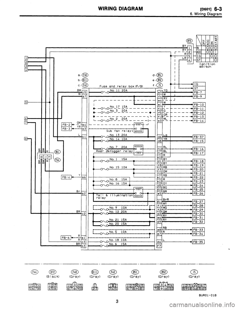
6-3
[D601]
WIRING
DIAGRAM
6
.
Wiring
Diagram
6
.
Wiring
Diagram
Batterycurrent
1
.
POWER
SUPPLY
ROUTING
Current
fromignition
switch
IG
terminal
---
Current
fromignition
switch
ACC
terminal
-------
Other
currents
Mainfuse
box
(M/B)
g27
SBF-5
45A
~
L
SBF-4
45A
,
BY
r-,
coc_
:
/CA
1
Do
BF-1
30A
BF-2
30A
N
m
m
M/B
FUSE/RELAY
LOCATION
826
-
MB-1
2
Rw
M
B-2
1
MB-3
R
-
MB-4
(
:8
~V
:
9)
,
R
F35
Headlight
No
.
22
15A
5
W
relay
LHNo
.
23
20A
Br
6
°
No
.
24
15A
RL
-----
---------
------0'
~-P--
1
---------°^----
MB-6
7
LB
7
No
.
26
15A
BY
°
~
~
_
No
.
25
15A
3
--°--°
BR
MB-8
.J
4
LR
2
MB-9
Headlight
relay
RH
F38
r~W
WC
relay
holder
mmllmm
O
~
SBFSBF
~~~
~
Head
i~25
N0
'
24
Headlight
4A
No,
relay
RH
~
SBF
~
38fSBf
N0
.
b
F/B
a
N0
.
--
2
:
0
N0
.f
o
N
.
176
N
RU7
.
R-DEF
N0
.
7
N0
.
N
.
3
0N
.
It
.4
~~
P
I
.7
LEI]
o
O
N0
.
19N0
.
12N0
.
~y~~~,~~~
ILLUrtI
.
O
N0.21
N0
.
14
N0
.7
MAIN
FAN
,
D
2
IF--
F26
F38
(B
I
ec
k)
2
B27
123
--'----
ALT-1
B26
(B
I
ac
k)
F26
(Grey)
12
F35
(B
I
ec
k)
1234
5678
BURO1-01A
Page 174 of 2890

WIRING
DIAGRAM
[nso1i
6-3
6
.
Wiring
Diagram
mm~
86I
O7
M
F44
m
a
:
F40
b
:
Bill
c
:
F42
Fuse
end
relay
box
(F/B)
BN
CSNo
.
11
20A
e7
No
.
17
15A
"
--O'~-o------------
NO
.
3
20A
----
~
'
--0
~4-----
-t
L
.__
.
.--
..__
.--
~~-~-0-
No-
.
-
2
-
20A
-------1-
FB-2
~R
e4
----------
FB-3
-°-
a3
-
---
--------°-°-°------
Y
-
Sub
fan
re
la
1
0
L
b
1
No
.
13
20A
_
_
No
.
14
l0A
FB-4
B72
U-
o
UaZ
i
o
RY
1
Br
-
-R
2
ACC
U
LR
5
IG-I
ST
Ignition
switch
d
:
BSl
I
e
:
852
I
f
:
i5
IG
e9
w~
__
.
.--
St
FB-7
f4
FB-9
e4
RY
W
e1
Y
FB-10
fll
f5
-
G
-
-----
--
-
-
FB-11
FB-
2
1
fl
R
1
--
-
-
FB-13
e3
-----
FB-14
No
.
OA
°
---°-
efo
er
relay
No
.
1
15A
No
.
15
l0A
_
No
.
8
15A
No
.
16
15A
F
B-37
YR
--
B
15
RL
°---
--------------
FB-16
BL
FB-17
BYBY
FB-18
RB
FB-19
GW
FB-20
RB
FB-21
FB-22
-
GY
FB23
-
BGF824
F
tE
---------------
-
B-25
---
r
iaii&
iiiumination
l~l
relay
,
BrR
~
-
dll
T
FB
27
___
..
.__--___J
~
_
.____
.__-
i
wG
.
.____
.__
._._.
FB-28
.
9
l0A
NoBRNo
.
1
A2
20
d
Gw
-
c2
3
FB30RY
5A
21
No
.
1
d9RY32
FB-
No
.
20
15A
~-°
.O'`
O-No_
5
__
l0A--------------
-7
R_-_-_°-----°--
FB-3FB-6
,
t
e4
R
N
o
.18
l0A
L
BRc3
6
1
SAd4
FB-35
F44872F40
Blll
F42
851
B52
i5
(B
I
ack)
(Gray)
(Gray)(Gray)(Gray)(Gray)(Gray)
1
2
34
123
5678
456
1
23
45
6789
0
213
342
678910151
ffm~i~
2131
7
7891
1112
891
11
1
1415
BUR01-018
3
Page 175 of 2890
![SUBARU LEGACY 1996 Service Repair Manual
s-$
[D601]
WIRING
DIAGRAM
6
.
Wiring
Diagram
No
.
Load
MB-2
Powerwindow
circuit
breaker
Engine
control
module
Fuel
pump
relay
MB-3
Main
relay
OBD-II
service
connector
MB-4A/C
relay
holder
MB- SUBARU LEGACY 1996 Service Repair Manual
s-$
[D601]
WIRING
DIAGRAM
6
.
Wiring
Diagram
No
.
Load
MB-2
Powerwindow
circuit
breaker
Engine
control
module
Fuel
pump
relay
MB-3
Main
relay
OBD-II
service
connector
MB-4A/C
relay
holder
MB-](/manual-img/17/57433/w960_57433-174.png)
s-$
[D601]
WIRING
DIAGRAM
6
.
Wiring
Diagram
No
.
Load
MB-2
Powerwindow
circuit
breaker
Engine
control
module
Fuel
pump
relay
MB-3
Main
relay
OBD-II
service
connector
MB-4A/C
relay
holder
MB-6
Headlight
LH
Diode
(Lighting)
Lighting
switch
Combination
meter
M
B_$
Headlight
RH
Combination
meter
Door
lock
timer
MB-9
Luggage
room
light
Radio
Room
light
MB-10
A/C
relay
holder
ALT-1
Combination
meter
IG
A/C
relay
holder
Cruise
control
module
ST
Engine
control
module
Inhibitor
switch
FB-2
Diode
(A/C)
Sub
fan
motor
FB-3
Sub
fan
relay-2
Engine
control
module
Fuel
pump
relay
FB-4
Ignition
coil
Transmission
control
module
Side
marker
light
LH
FB-6
Side
marker
light
RH
FB-7Door
lock
timer
FB-9Hazard
switch
AT
shift
lock
control
module
FB-10
Key
warning
switch
Power
antenna
FB-11
Radio
FB-12
Cigarette
lighter
FB-13
Remote
control
rearview
mirrorswitch
AT
shift
lock
control
module
Combination
switch
Front
washer
motor
FB-14
Front
wipermotor
Rear
washer
motor
Rear
wipermotor
Rear
wiper
relay
FB-15Transmission
control
module
Na
Load
Rear
defogger
FB-16
Rear
defogger
condenser
Reardefogger
switch
FB-17
Rear
defogger
switch
FB-18
AT
shift
lock
control
module
Inhibitor
switch
FB-19
Hazard
switch
Combination
meter
FB-20
Mode
control
panel
FB-21
Combination
meter
(Airbag)
Blower
motor
relay
Check
connector
FB-22
FRESH/RECIRC
actuator
Mode
actuator
Powerwindow
relay
Seat
belt
timer
FB-23
Airbag
.
control
module
FB-24
Airbag
control
module
FB-25
Lighting
switch
FB-26
Parking
switch
FB-27
Parking
switch
FB-28
Illumination
light
FB-29
Illumination
light
FB-30
Stop
light
switch
Stop
&
brake
switch
FB-31
Horn
relay
FB-32
Blower
motor
relay
FB-33
Parking
switch
License
plate
light
LH
License
plate
light
RH
FB-34
Rear
combination
light
LH
Rear
combination
light
RH
Rear
finisher
light
LH
Rear
finisher
light
RH
FB-35
Cruise
control
main
switch
Cruise
control
module
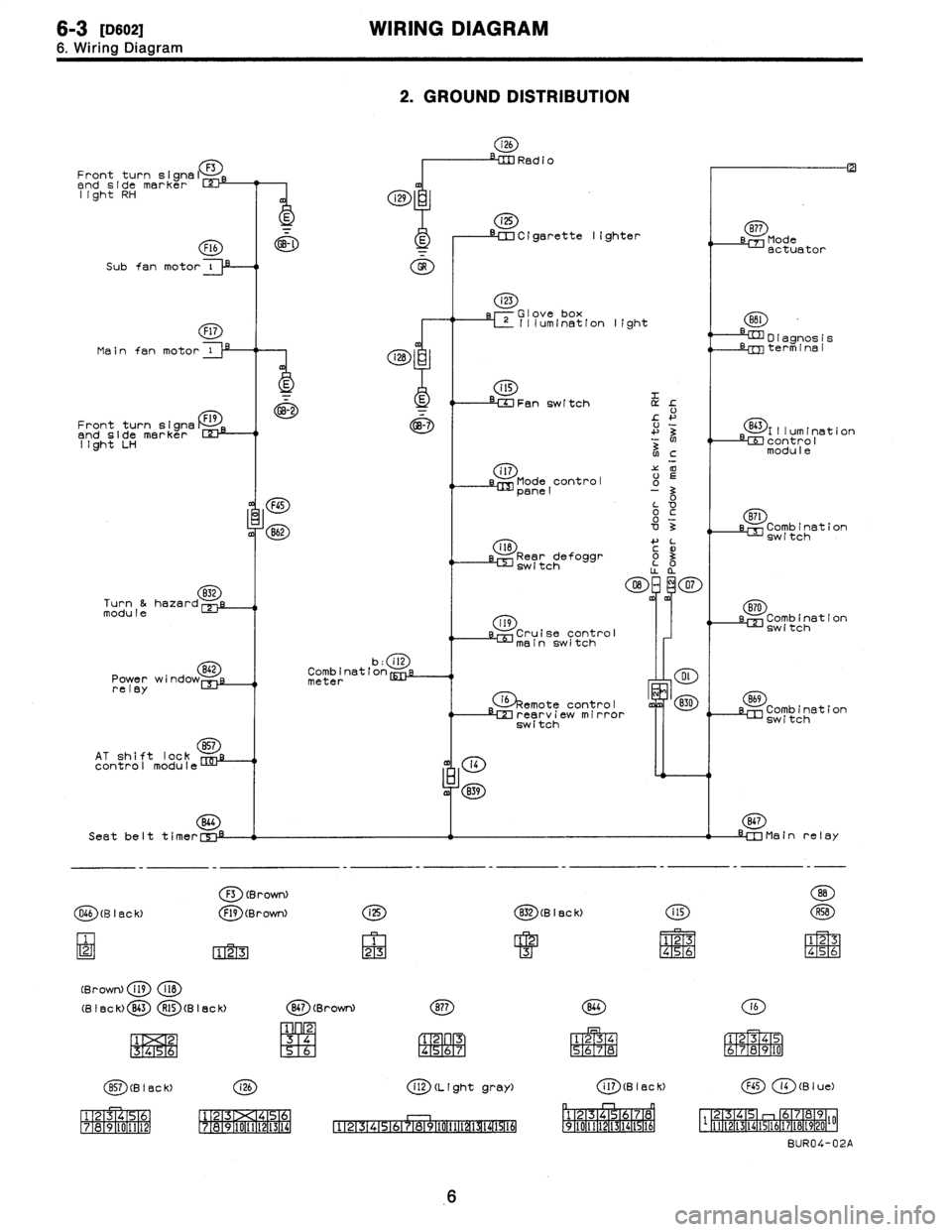
Page 176 of 2890

6-3
[0602
WIRING
DIAGRAM
6
.
Wiring
Diagram
2
.
GROUND
DISTRIBUTION
i26
RedioFront
turn
signal
F3
end
side
marker
rm
light
RH
i
i29
i25
~~--
--
a
--~~
Cigarette
lighter
sB77
Mode
F16
~-~
E
I
actuator
Subfan
motor
i
O
Main
fan
motor
Front
turn
signs
Dend
side
marker
123-1
light
LH
832
Turn
&hazardmodule
Power
wi
relay
AT
shift
lock
857
control
module
(28
:
E
GB-2
FGS
B62
b
:
ill
Combination
meter
(4
m
839
Seat
belt
t
i
mer
C',"-i
F3
(BrowN
O66
(B
I
BC
k)
F19
(Brown)
123
(Brown)
fig
118
(B
I
ac
k)
B43
R15
(B
I
ec
k)
1
2
1
3
1
4
151
6
i
25
1
23
i23
rGlove
box
L~
Illum(nation
light
Fan
switch
L
!-
+'
3
N
NC
i
l7'Z
00
Mode
control
o
panel
0o
~c
'0o
3
il8
4-
L
3
Rear
defoggr
~
o3
switch
O
~m~
07
m
119
Cruise
control
mainswitch
G)§emote
ontro
I
c
LM
rearv
i
e
irror
switch
(g)
(B
I
ec
k)
CD
1
23
4
M
S6
(g)(Brown)
(~D
1
23
[96
R4
;6R7
(~D(BISCK)
(~D
ff~
1516-111
12131><14151
111213
171a191101111121
1718191101111121131141
CD
(L
(ght
gray)
4
'
:F
151617
P911011111~~
D
I
agnos
1
s
Lrm
term
1
na
I
(E~)l
II
um
I
nat
1
on
LEE
contro
I
modu
I
e
(ED
LM
Combination
switch
870
sl=
Combination
switch
B69
Combination
switch
867
-IM
Main
relay
141516
(E)
(a)
1
234
S6JR8
161
r
1
E319
1101
(aD
(B
I
ac
K)
(B
I
u
e)
p
r-1
n
~1
1
F2-1[3
1
f41516
1
7a
0
1
2-
F
-
1q,
[3
46
112-2TI-3114115116117118119120
I'F
BUR04-02A
6