Page 1254 of 1954
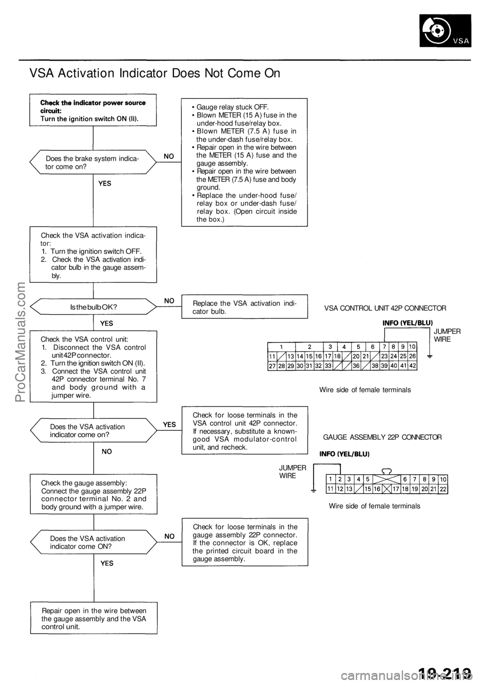
VSA Activation Indicator Does Not Come On
Does the brake system indica-
tor come on?
Check the VSA activation indica-
tor:
1. Turn the ignition switch OFF.
2. Check the VSA activation indi-
cator bulb in the gauge assem-
bly.
Is the bulb OK?
Check the VSA control unit:
1. Disconnect the VSA control
unit 42P connector.
2. Turn the ignition switch ON (II).
3. Connect the VSA control unit
42P connector terminal No. 7
and body ground with a
jumper wire.
Does the VSA activation
indicator come on?
Check the gauge assembly:
Connect the gauge assembly 22P
connector terminal No. 2 and
body ground with a jumper wire.
Does the VSA activation
indicator come ON?
Repair open in the wire between
the gauge assembly and the VSA
control unit.
Gauge relay stuck OFF.
Blown METER (15 A) fuse in the
under-hood fuse/relay box.
Blown METER (7.5 A) fuse in
the under-dash fuse/relay box.
Repair open in the wire between
the METER (15 A) fuse and the
gauge assembly.
Repair open in the wire between
the METER (7.5 A) fuse and body
ground.
Replace the under-hood fuse/
relay box or under-dash fuse/
relay box. (Open circuit inside
the
box.)
Replace the VSA activation indi-
cator bulb.
VSA CONTROL UNIT 42P CONNECTOR
JUMPER
WIRE
Check for loose terminals in the
VSA control unit 42P connector.
If necessary, substitute a known-
good VSA modulator-control
unit, and recheck.
JUMPER
WIRE
Wire side of female terminals
GAUGE ASSEMBLY 22P CONNECTOR
Wire side of female terminals
Check for loose terminals in the
gauge assembly 22P connector.
If the connector is OK, replace
the printed circuit board in the
gauge assembly.ProCarManuals.com
Page 1255 of 1954
Troubleshooting
VSA Activation Indicator Does Not Go Off
Check for a short to body ground
in the INFO circuit:
1. Disconnect the VSA control
unit 42P connector.
2. Turn the ignition switch ON (II).
Does the VSA activation
indicator go off?
Repair short to body ground in the
wire between the gauge assembly
and the VSA control unit.
Check for loose terminals in the
VSA control unit 42P connector.
If necessary, substitute a known-
good VSA modulator-control
unit, and recheck.ProCarManuals.com
Page 1256 of 1954
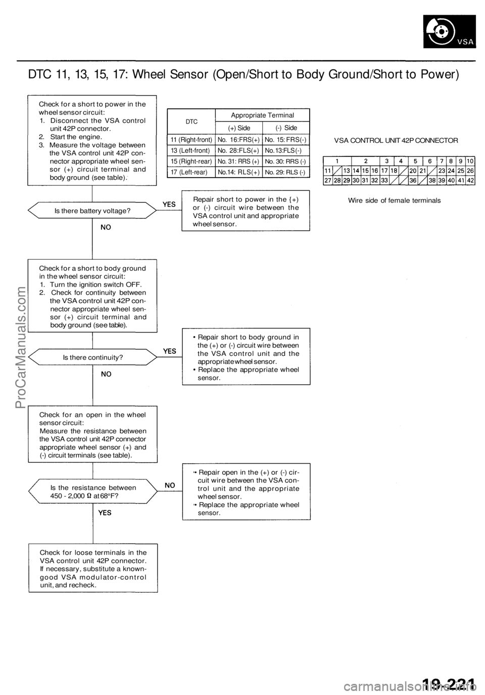
DTC 11, 13, 15, 17: Wheel Sensor (Open/Short to Body Ground/Short to Power)
Check for a short to power in the
wheel sensor circuit:
1. Disconnect the VSA control
unit 42P connector.
2. Start the engine.
3. Measure the voltage between
the VSA control unit 42P con-
nector appropriate wheel sen-
sor (+) circuit terminal and
body ground (see table).
DTC
11 (Right-front)
13 (Left-front)
15 (Right-rear)
17 (Left-rear)
Appropriate Terminal
(+) Side
No. 16:FRS(+)
No. 28:FLS(+)
No. 31: RRS (+)
No.14: RLS(+)
(-) Side
No. 15: FRS(-)
No. 13:FLS (-)
No. 30:
RRS
(-)
No. 29: RLS (-)
VSA CONTROL UNIT 42P CONNECTOR
Is there battery voltage?
Repair short to power in the {+)
or (-) circuit wire between the
VSA control unit and appropriate
wheel sensor.
Wire side of female terminals
Check for a short to body ground
in the wheel sensor circuit:
1. Turn the ignition switch OFF.
2. Check for continuity between
the VSA control unit 42P con-
nector appropriate wheel sen-
sor (+) circuit terminal and
body ground (see table).
Is there continuity?
Repair short to body ground in
the (+) or (-) circuit wire between
the VSA control unit and the
appropriate wheel sensor.
Replace the appropriate wheel
sensor.
Check for an open in the wheel
sensor circuit:
Measure the resistance between
the VSA control unit 42P connector
appropriate wheel sensor (+) and
(-) circuit terminals (see table).
Is the resistance between
450 - 2,000 at 68°F?
• Repair open in the (+) or (-) cir-
cuit wire between the VSA con-
trol unit and the appropriate
wheel sensor.
• Replace the appropriate wheel
sensor.
Check for loose terminals in the
VSA control unit 42P connector.
If necessary, substitute a known-
good VSA modulator-control
unit, and recheck.ProCarManuals.com
Page 1263 of 1954
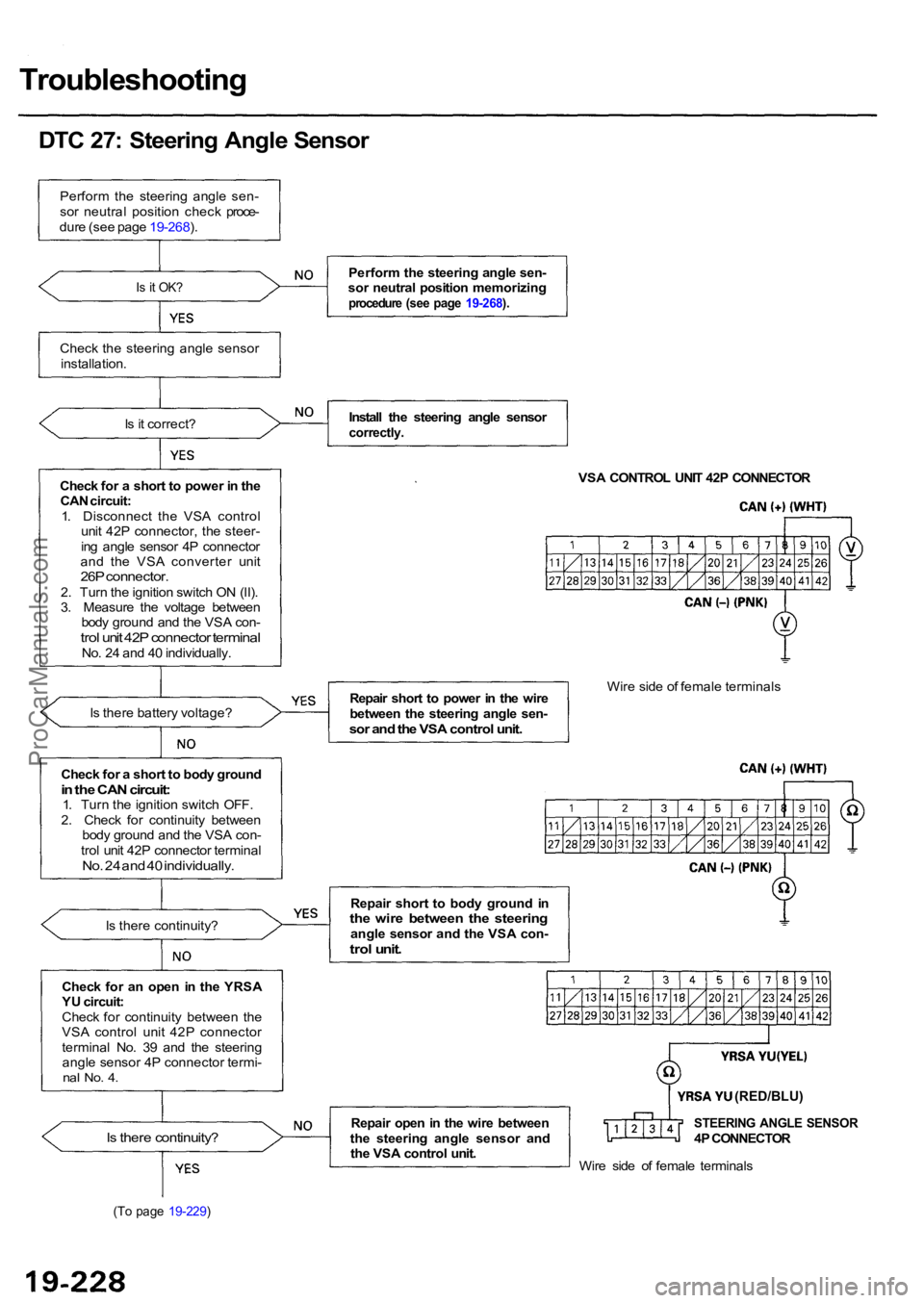
Troubleshooting
DTC 27: Steering Angle Sensor
Perform the steering angle sen-
sor neutral position check proce-
dure (see page 19-268).
Is it OK?
Check the steering angle sensor
installation.
Is it correct?
Check for a short to power in the CAN circuit:
1. Disconnect the VSA control unit 42P connector, the steer-
ing angle sensor 4P connector
and the VSA converter unit
26P connector.2. Turn the ignition switch ON (II).
3. Measure the voltage between body ground and the VSA con-
trol unit 42P connector terminalNo. 24 and 40 individually.
Is there battery voltage?
Is there continuity?
Check for an open in the YRSA
YU circuit:
Check for continuity between the
VSA control unit 42P connector
terminal No. 39 and the steering angle sensor 4P connector termi-
nal No. 4.
Is there continuity?
(To page 19-229)
Perform the steering angle sen-
sor neutral position memorizing
procedure (see page 19-268).
Install the steering angle sensorcorrectly.
VSA CONTROL UNIT 42P CONNECTOR
Repair short to power in the wire
between the steering angle sen-
sor and the VSA control unit.
Wire side of female terminals
Repair short to body ground in
the wire between the steeringangle sensor and the VSA con-trol unit.
Repair open in the wire between
the steering angle sensor and the VSA control unit.STEERING ANGLE SENSOR4P CONNECTOR
Wire side of female terminals
Check for a short to body ground
in the CAN circuit:1. Turn the ignition switch OFF.
2. Check for continuity between body ground and the VSA con-
trol unit 42P connector terminal
No. 24 and 40 individually.
(RED/BLU)
ProCarManuals.com
Page 1273 of 1954
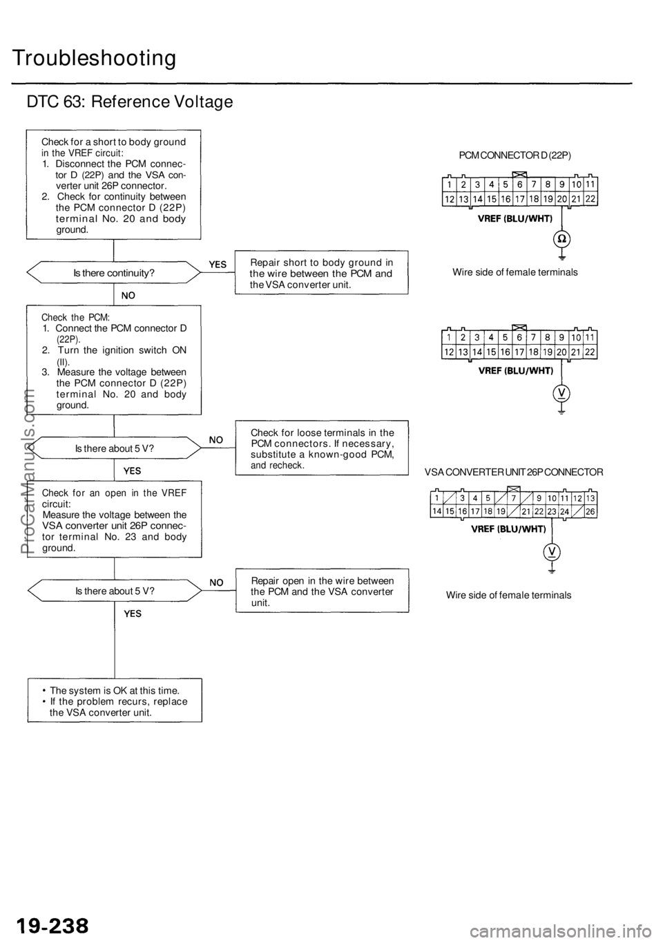
Troubleshooting
DTC 63: Reference Voltage
Check for a short to body ground
in the VREF circuit:
1. Disconnect the PCM connec-
tor D
(22P)
and the VSA
con-
verter unit 26P connector.
2. Check for continuity between
the PCM connector D (22P)
terminal No. 20 and body
ground.
Is there continuity?
Is there about 5 V?
Check for an open in the VREF
circuit:
Measure the voltage between the
VSA converter unit 26P connec-
tor terminal No. 23 and body
ground.
Is there about 5 V?
The system is OK at this time.
If the problem recurs, replace
the VSA converter unit.
Repair short to body ground in
the wire between the PCM and
the VSA converter unit.
Check for loose terminals in the
PCM connectors. If necessary,
substitute a known-good PCM,
and recheck.
PCM CONNECTOR D (22P)
Wire side of female terminals
VSA CONVERTER UNIT 26P CONNECTOR
Repair open in the wire between
the PCM and the VSA converter
unit.
Wire side of female terminals
Check the PCM:
1. Connect the PCM connector D
(22P).
2. Turn the ignition switch ON
(II).
3. Measure the voltage between
the PCM connector D (22P)
terminal No. 20 and body
ground.ProCarManuals.com
Page 1292 of 1954
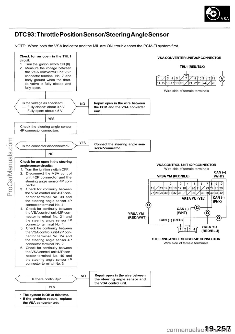
DTC 93: Throttle Position Sensor/Steering Angle Sensor
NOTE: When both the VSA indicator and the MIL are ON, troubleshoot the PGM-FI system first.
Check for an open in the THL1circuit:1. Turn the ignition switch ON (II).
2. Measure the voltage between
the VSA converter unit 26Pconnector terminal No. 7 and body ground when the throt-
tle valve is fully closed and
fully open.
Is the voltage as specified?
— Fully closed: about 0.5 V
— Fully open: about 4.5 V
Check the steering angle sensor
4P connector connection.
Is the connector disconnected?
Check for an open in the steering
angle sensor circuits:
1. Turn the ignition switch OFF.2. Disconnect the VSA controlunit 42P connector and thesteering angle sensor 4P con-nector.
3. Check for continuity between
the VSA control unit 42P con-nector terminal No. 39 and
the steering angle sensor 4P
connector terminal No. 4.
4. Check for continuity between
the VSA control unit 42P con-nector t e r m i n a l No. 21 and
the steering angle sensor 4P
connector terminal No. 1.
5. Check for continuity between
the VSA control unit 42P con-nector terminal No. 24 and
the steering angle sensor 4P
connector terminal No. 2.
6. Check for continuity between
the VSA control unit 42P con-nector terminal No. 40 and
the steering angle sensor 4P
connector terminal No. 3.
Is there continuity?
The system is OK at this time. If the problem recurs, replace
the VSA converter unit. VSA CONVERTER UNIT 26P CONNECTOR
Repair open in the wire between
the PCM and the VSA converter unit.
Connect the steering angle sen-
sor 4P connector. VSA CONTROL UNIT 42P CONNECTORWire side of female terminals
STEERING ANGLE SENSOR 4P CONNECTOR Wire side of female terminals
Repair open in the wire between
the steering angle sensor and
the VSA control unit. Wire side of female terminals
YRSA YM
(RED/WHT) CAN (-)
(WHT)
CAN (+) (RED) YRSA YU
(RED/BLU)
ProCarManuals.com
Page 1306 of 1954
Precharge Brake Line Bleeding
1. Connect the SCS service connector to the service check connector (2P) under the glove box.
2. Press the parking brake pedal.
3. Press the VSA off switch, and hold it.
4. Turn the ignition switch ON (II).
5. Release the VSA off switch after the VSA activation indicator goes off twice.
6. Press the VSA off switch after the VSA activation indicator comes on.
7. Release the VSA off switch after the VSA activation indicator goes off.
8. Press the VSA off switch after the VSA activation indicator starts blinking.
9. Release the VSA off switch after the VSA activation indicator stops blinking.
10. Turn the ignition switch OFF, then repeat steps 2 through 10 for 4 times.ProCarManuals.com
Page 1458 of 1954
Both Fans Low Speed and Radiator Fan High Speed
Both fans do not run at low speed,
and radiator fan does not run at
high speed (but condenser fan
runs at high speed).
Check for an open in the wire:
1. Disconnect the radiator fan 2P
connector.
2. Turn the ignition switch ON (II)
and the A/C system on to
MAX COOL.
3. Measure the voltage between
the No. 2 terminal and body
ground.
RADIATOR FAN 2P CONNECTOR
Wire side of female terminals
Is there battery voltage?
Repair open in the wire between
the radiator fan relay, the radia-
tor fan main relay and the radia-
tor
fan.
Is there continuity?
Check for an open in the wire
between the radiator fan and
body ground. If the wire is OK,
check for poor ground at G302.
Check for an open in the wire:
1. Turn the ignition switch OFF.
2. Check for continuity between
the No. 1 terminal of the radi-
ator fan 2P connector and
body ground.
Replace the radiator fan motor.ProCarManuals.com