Page 1714 of 1954

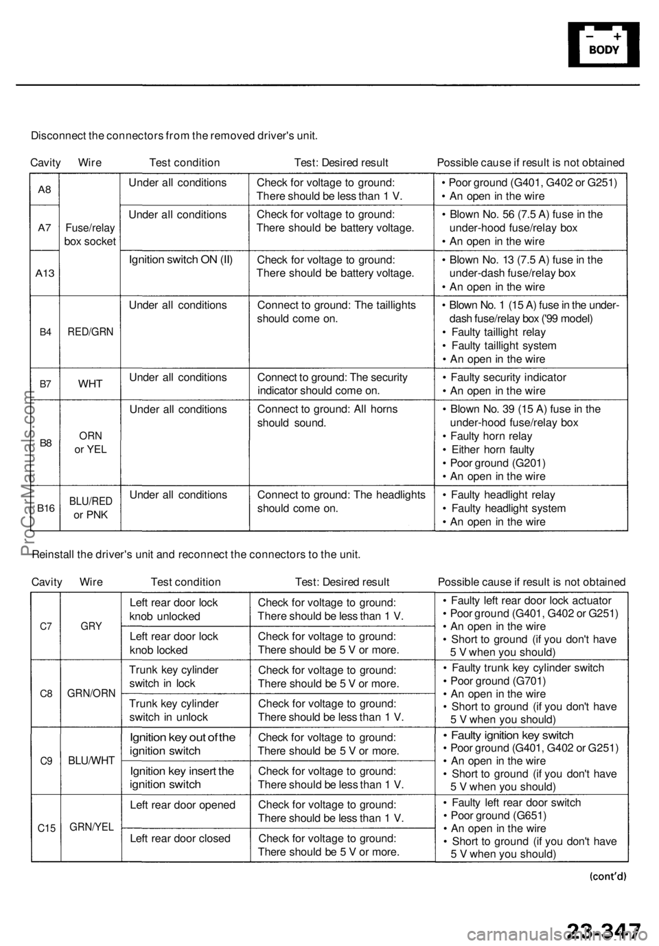
Disconnect th e connector s fro m th e remove d driver' s unit .
Cavit y Wir e Test conditio n Test: Desire d resul t Possible caus e if resul t i s no t obtaine d
A8
A7
A1 3
B4
B7
B8
B1 6
Fuse/rela y
box socke t
RED/GR N
WHT
ORN
or YE L
BLU/RE D
or PN K
Unde r al l condition s
Unde r al l condition s
Ignition switc h O N (II )
Unde r al l condition s
Unde r al l condition s
Unde r al l condition s
Unde r al l condition sChec
k fo r voltag e t o ground :
Ther e shoul d b e les s tha n 1 V .
Chec k fo r voltag e t o ground :
Ther e shoul d b e batter y voltage .
Chec k fo r voltag e t o ground :
Ther e shoul d b e batter y voltage .
Connec t t o ground : Th e taillight s
shoul d com e on .
Connec t t o ground : Th e securit y
indicato r shoul d com e on .
Connec t t o ground : Al l horn s
shoul d sound .
Connec t t o ground : Th e headlight s
shoul d com e on . •
Poo r groun d (G401 , G40 2 o r G251 )
• A n ope n in th e wir e
• Blow n No . 5 6 (7. 5 A ) fus e in th e
under-hoo d fuse/rela y bo x
• A n ope n in th e wir e
• Blow n No . 1 3 (7. 5 A ) fus e in th e
under-das h fuse/rela y bo x
• A n ope n in th e wir e
• Blow n No . 1 (1 5 A ) fus e in th e under -
das h fuse/rela y bo x ('9 9 model )
• Fault y tailligh t rela y
• Fault y tailligh t syste m
• A n ope n in th e wir e
• Fault y securit y indicato r
• A n ope n in th e wir e
• Blow n No . 3 9 (1 5 A ) fus e in th e
under-hoo d fuse/rela y bo x
• Fault y hor n rela y
• Eithe r hor n fault y
• Poo r groun d (G201 )
• A n ope n in th e wir e
• Fault y headligh t rela y
• Fault y headligh t syste m
• A n ope n in th e wir e
Reinstal l th e driver' s uni t an d reconnec t th e connector s to th e unit .
Cavit y Wir e Test conditio n Test: Desire d resul t Possible caus e if resul t i s no t obtaine d
C7
C 8
C9
C1 5
GR Y
GRN/OR N
BLU/WHT
GRN/YE L
Left rea r doo r loc k
kno b unlocke d
Lef t rea r doo r loc k
kno b locke d
Trun k ke y cylinde r
switc h i n loc k
Trun k ke y cylinde r
switc h i n unloc k
Ignition ke y ou t o f th e
ignitio n switc h
Ignitio n ke y inser t th e
ignitio n switc h
Left rea r doo r opene d
Lef t rea r doo r close d Chec
k fo r voltag e t o ground :
Ther e shoul d b e les s tha n 1 V .
Chec k fo r voltag e t o ground :
Ther e shoul d b e 5 V or more .
Chec k fo r voltag e t o ground :
Ther e shoul d b e 5 V or more .
Chec k fo r voltag e t o ground :
Ther e shoul d b e les s tha n 1 V .
Chec k fo r voltag e t o ground :
Ther e shoul d b e 5 V or more .
Chec k fo r voltag e t o ground :
Ther e shoul d b e les s tha n 1 V .
Chec k fo r voltag e t o ground :
Ther e shoul d b e les s tha n 1 V .
Chec k fo r voltag e t o ground :
Ther e shoul d b e 5 V or more . •
Fault y lef t rea r doo r loc k actuato r
• Poo r groun d (G401 , G40 2 o r G251 )
• A n ope n i n th e wir e
• Shor t t o groun d (i f yo u don' t hav e
5 V whe n yo u should )
• Fault y trun k ke y cylinde r switc h
• Poo r groun d (G701 )
• A n ope n in th e wir e
• Shor t t o groun d (i f yo u don' t hav e
5 V whe n yo u should )
• Fault y ignitio n ke y switc h
• Poo r groun d (G401 , G40 2 o r G251 )
• A n ope n in th e wir e
• Shor t t o groun d (i f yo u don' t hav e
5 V whe n yo u should )
• Fault y lef t rea r doo r switc h
• Poo r groun d (G651 )
• A n ope n in th e wir e
• Shor t t o groun d (i f yo u don' t hav e
5 V whe n yo u should )
ProCarManuals.com
Page 1715 of 1954

Security Syste m
Contro l Uni t Inpu t Tes t (cont'd )
NOTE:
• Befor e testing , g o t o th e Troubleshootin g Guid e (se e pag e 23-244 ). B e sur e t o g o throug h self-diagnosi s functio n
mode s 1 an d 2 (se e page s 23-24 8 an d 23-252 ).
• Al l connecto r view s ar e fro m th e wir e sid e o f femal e terminal s unles s otherwis e noted .
Multiple x Contro l Uni t (Passenger's) :
1 . Remov e th e righ t kic k pane l (se e sectio n 20 ).
2 . Disconnec t th e 22 P an d 26 P connectors , the n remov e th e passenger' s uni t (se e pag e 23-246 ).
3 . Inspec t th e connecto r an d socke t terminal s to b e sur e the y ar e al l makin g goo d contact .
• I f th e terminal s ar e bent , loos e o r corroded , repai r the m a s necessary , an d rechec k th e system .
• I f th e terminal s loo k OK , mak e th e followin g inpu t test s a t th e connector .
I f an y tes t indicate s a problem , fin d an d correc t th e cause , the n rechec k th e system .
I f al l th e inpu t test s prov e OK , th e contro l uni t mus t b e faulty ; replac e it .
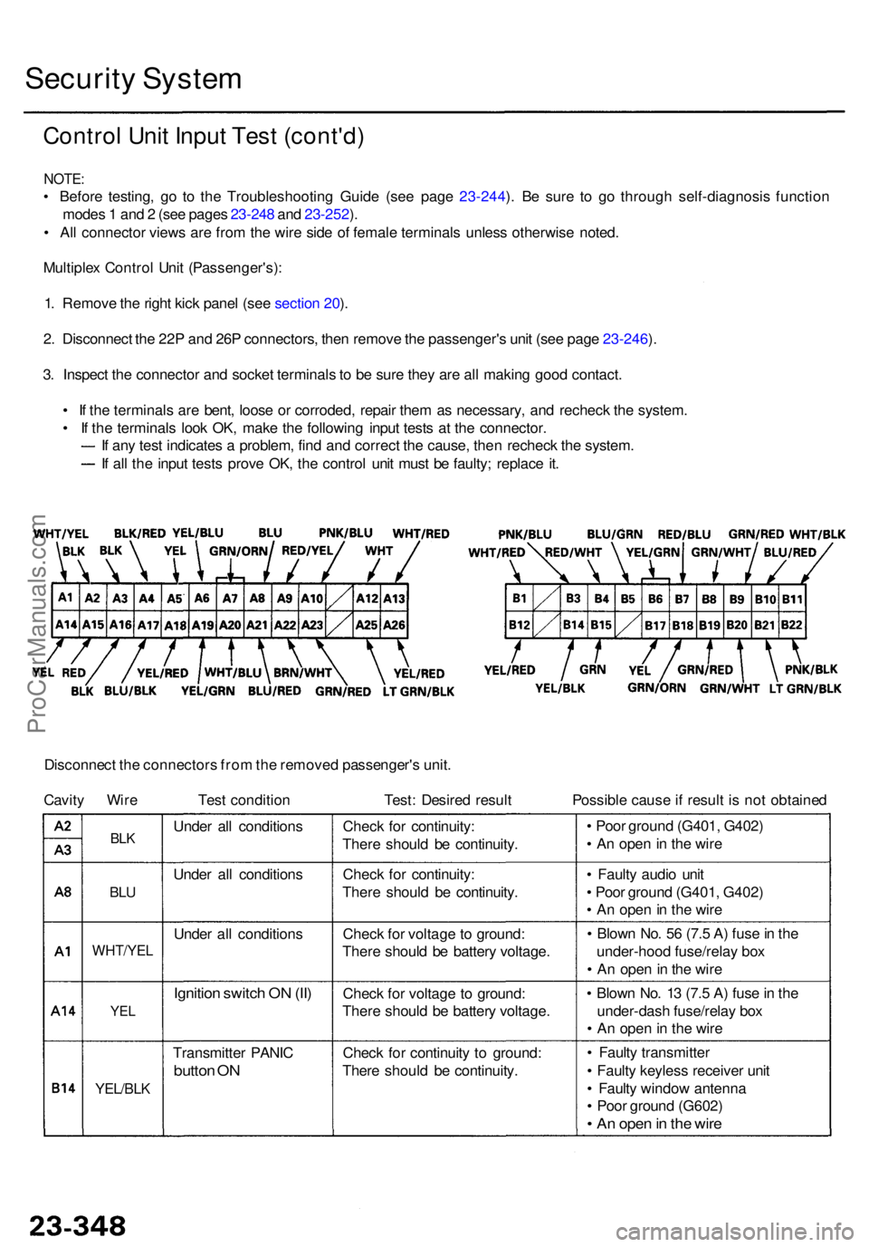
Disconnec t th e connector s fro m th e remove d passenger' s unit .
Cavit y Wir e Tes t conditio n Test : Desire d resul t Possibl e caus e if resul t i s no t obtaine d
BLK
BLU
WHT/YE L
YEL
YEL/BL K
Transmitte r PANI C
button O N
Unde r al l condition s
Unde r al l condition s
Unde r al l condition s
Ignition switc h O N (II )
Chec k fo r continuit y t o ground :
Ther e shoul d b e continuity .
Chec
k fo r voltag e t o ground :
Ther e shoul d b e batter y voltage .
Chec
k fo r voltag e to ground :
Ther e shoul d b e batter y voltage .
Chec
k fo r continuity :
Ther e shoul d b e continuity .
Chec
k fo r continuity :
Ther e shoul d b e continuity . •
Poo r groun d (G401 , G402 )
• A n ope n in th e wir e
• Fault y audi o uni t
• Poo r groun d (G401 , G402 )
• A n ope n in th e wir e
• Blow n No . 5 6 (7. 5 A ) fus e in th e
under-hoo d fuse/rela y bo x
• A n ope n in th e wir e
• Blow n No . 1 3 (7. 5 A ) fus e in th e
under-das h fuse/rela y bo x
• A n ope n in th e wir e
• Fault y transmitte r
• Fault y keyles s receive r uni t
• Fault y windo w antenn a
• Poo r groun d (G602 )
• A n ope n in th e wir e
ProCarManuals.com
Page 1792 of 1954

Description
SRS Airbag System - '96 - 98 Models
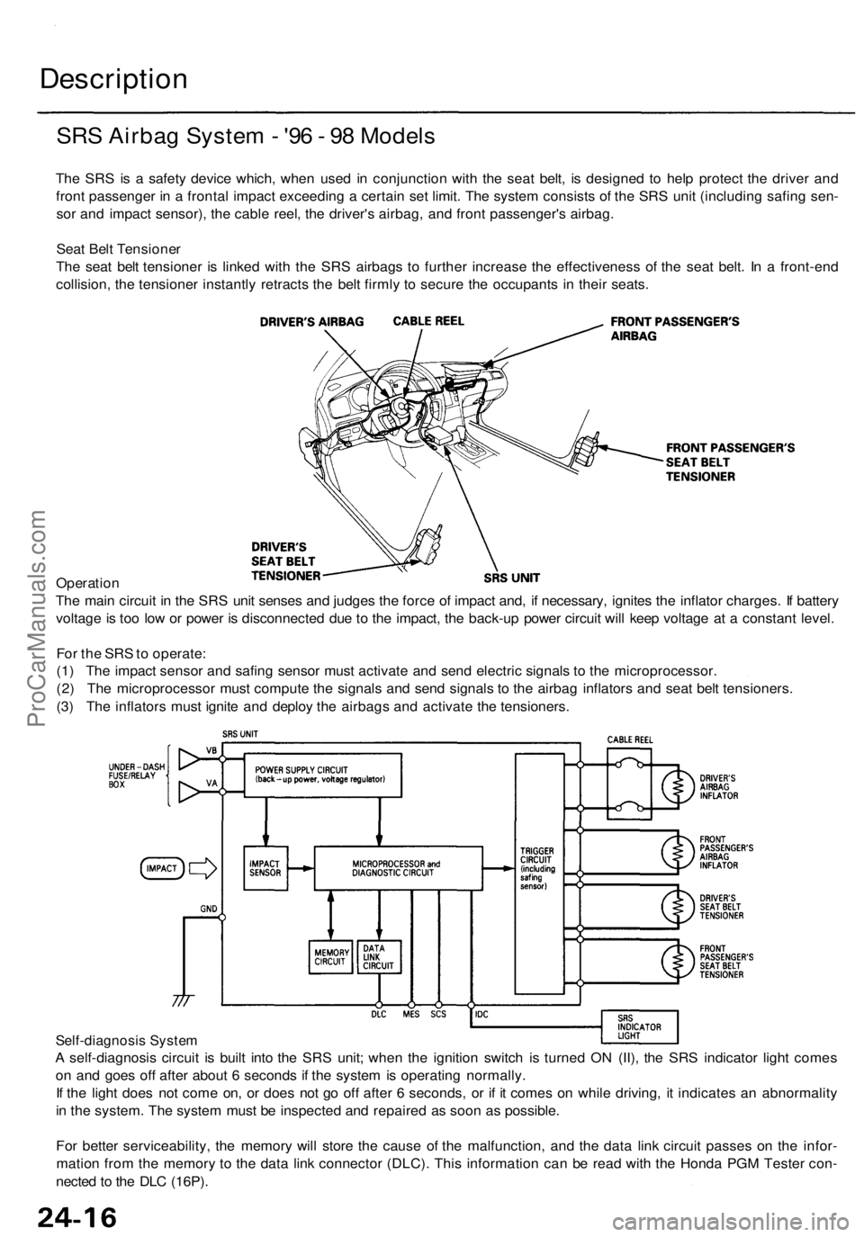
The SRS is a safety device which, when used in conjunction with the seat belt, is designed to help protect the driver and
front passenger in a frontal impact exceeding a certain set limit. The system consists of the SRS unit (including safing sen-
sor and impact sensor), the cable reel, the driver's airbag, and front passenger's airbag.
Seat Belt Tensioner
The seat belt tensioner is linked with the SRS airbags to further increase the effectiveness of the seat belt. In a front-end
collision, the tensioner instantly retracts the belt firmly to secure the occupants in their seats.
Operation
The main circuit in the SRS unit senses and judges the force of impact and, if necessary, ignites the inflator charges. If battery
voltage is too low or power is disconnected due to the impact, the back-up power circuit will keep voltage at a constant level.
For the SRS to operate:
(1) The impact sensor and safing sensor must activate and send electric signals to the microprocessor.
(2) The microprocessor must compute the signals and send signals to the airbag inflators and seat belt tensioners.
(3) The inflators must ignite and deploy the airbags and activate the tensioners.
Self-diagnosis System
A self-diagnosis circuit is built into the SRS unit; when the ignition switch is turned ON (II), the SRS indicator light comes
on and goes off after about 6 seconds if the system is operating normally.
If the light does not come on, or does not go off after 6 seconds, or if it comes on while driving, it indicates an abnormality
in the system. The system must be inspected and repaired as soon as possible.
For better serviceability, the memory will store the cause of the malfunction, and the data link circuit passes on the infor-
mation from the memory to the data link connector (DLC). This information can be read with the Honda PGM Tester con-
nected to the DLC (16P).ProCarManuals.com
Page 1930 of 1954
DTC15-3
CAUTION: Whenever the ignition switch is ON (II), or has
been turned OFF for less than 3 minutes, be careful not
to bump the SRS unit or the side impact sensor; the
airbags could accidentally deploy and cause damage or
injuries.ProCarManuals.com
Page 1934 of 1954
6. Reconnect the airbag connector(s):
Front Passenger's Airbag:
• Connect the front passenger's airbag connector to
the SRS main harness connector, then install the
glove box.
Driver's Side:
• Connect the driver's airbag 2P connector to the cable
reel 2P connector, then install the access panel on the
steering wheel.
'96 - 98 Models
7. Reconnect the battery positive cable, then connect
the negative cable.
8. After installing the airbag, confirm proper system
operation:
• Turn the ignition switch ON (II); the SRS indica-
tor light should come on for about 6 seconds and
then go off.
• Make sure horn button works.
• Take a test drive, and make sure the cruise con-
trol switches work.
9. Enter the anti-theft code for the radio, then enter the
customer's radio station presets.
'99 - 01 ModelsProCarManuals.com
Page 1938 of 1954
12. Reconnect the battery positive cable, then the nega-
tive cable.
13. After installing the seat belt, confirm proper system
operation: Turn the ignition switch ON (II); the SRS
indicator light should come on for about 6 seconds
and then go off.
14. Enter the anti-theft code for the radio, then enter the
customer's radio station presets.ProCarManuals.com