Page 1511 of 1954
IGNITION CONTRO LMODULE (ICM )
UNDER-HOO D RELA YBOX B
DRIVER' S POWE R WINDO W MOTO R RELA Y B('98-0 1 models )• HOR N RELA Y('96-97 models )• POWE R WINDO W MASTE R SWITC H
RELA Y ('98-0 1 models )
CIGARETT E LIGHTE R RELA Y
• FRON T SEA T HEATE R RELA Y
('96-97 models )• DRIVER' S POWE R WINDO W MOTO R RELA Y A
('9 8-0 1 models )
SPAR K PLU G VOLTAG E
DETECTIO N MODUL E
DIMME R RELA Y •
AB S PUM P MOTO R RELA Y
('96-99 models )• VS A FAIL-SAF E RELA Y
('0 0-0 1 models )
• HEADLIGH T RELA Y
('96-98 models )• HEADLIGH T
LO W BEA M RELA Y
('99-01 models )
TAILLIGH T RELA Y
('9 6 - 9 8 models )
• HEADLIGH T HIG H BEA M RELA Y
('9 9-0 1 models )
UNDER-HOO
D
FUSE/RELAYBOX
ProCarManuals.com
Page 1520 of 1954
Ignition Switc h
Test
SRS component s ar e locate d i n thi s area . Revie w th e
SR S componen t locations , precautions , an d procedure s
i n th e SR S ( sectio n 24 ) befor e performin g repair s o r
service .
NOTE: Th e PC M memor y mus t b e rese t afte r reconnectin g
th e batter y (se e sectio n 11 ).
1 . Mak e sur e yo u hav e th e anti-thef t cod e fo r th e radi o
an d th e navigatio n system , the n writ e dow n th e fre -
quencie s fo r th e radio' s prese t buttons .
2 . Disconnec t th e batter y negativ e cable .
3 . Remov e th e dashboar d lowe r cove r (se e sectio n 20 ).
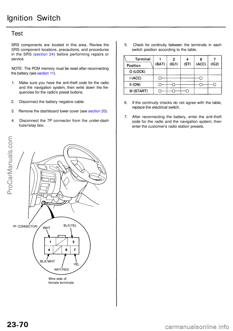
4 . Disconnec t th e 7 P connecto r fro m th e under-das h
fuse/rela y box .
7P CONNECTO R
Wire sid e o f
femal e terminal s
WHTBLK/YE L
YEL
WHT/RE D
BLK/WH T
5. Chec k fo r continuit y betwee n th e terminal s i n eac h
switc h positio n accordin g t o th e table .
6 . I f th e continuit y check s d o no t agre e wit h th e table ,
replac e th e electrica l switch .
7. Afte r reconnectin g th e battery , ente r th e anti-thef t
cod e fo r th e radi o an d th e navigatio n system , the n
ente r th e customer' s radi o statio n presets .
ProCarManuals.com
Page 1541 of 1954
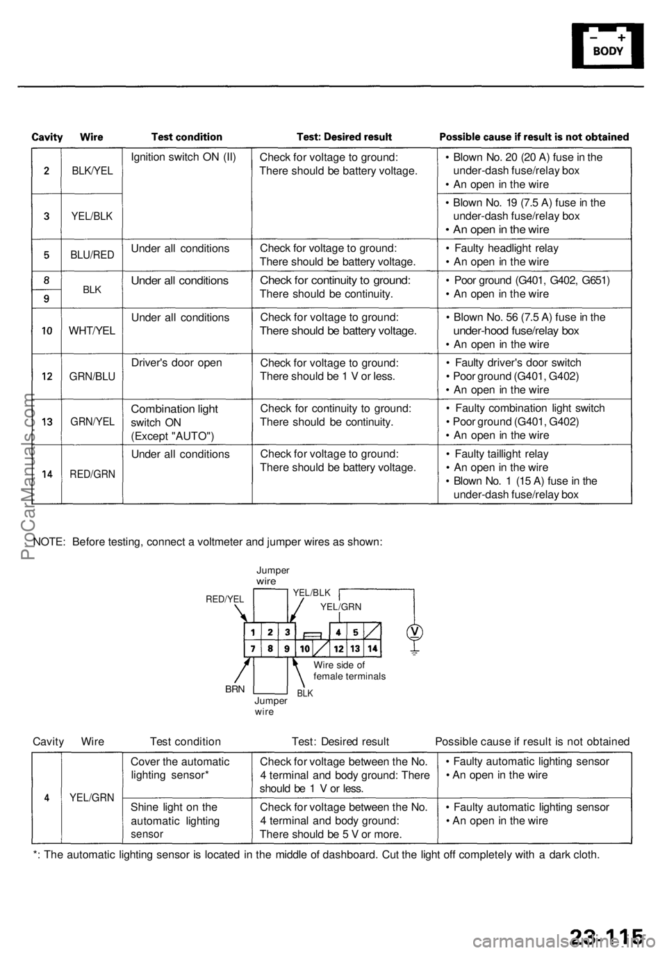
BLK/YEL
YEL/BLK
BLU/RE D
BLK
WHT/YE L
GRN/BLU
GRN/YE L
RED/GR N
Ignition switc h O N (II )
Unde r al l condition s
Under al l condition s
Under al l condition s
Driver' s doo r ope n
Combinatio n ligh t
switc h O N
(Excep t "AUTO" )
Unde r al l condition sChec
k fo r voltag e to ground :
Ther e shoul d b e batter y voltage .
Chec k fo r voltag e to ground:
Ther e shoul d b e batter y voltage .
Check fo r continuit y to ground :
There shoul d b e continuity .
Chec k fo r voltag e to ground :
There shoul d b e batter y voltage .
Check fo r voltag e t o ground :
Ther e shoul d b e 1 V or less .
Chec k fo r continuit y t o ground :
Ther e shoul d b e continuity .
Chec k fo r voltag e to ground :
Ther e shoul d b e batter y voltage .•
Blow n No . 2 0 (2 0 A ) fus e in th e
under-das h fuse/rela y bo x
• A n ope n in th e wir e
• Blow n No . 1 9 (7. 5 A ) fus e in th e
under-das h fuse/rela y bo x
• A n ope n in th e wir e
• Fault y headligh t rela y
• A n ope n in th e wir e
• Poo r groun d (G401 , G402 , G651 )
• A n ope n in th e wir e
• Blow n No . 5 6 (7. 5 A ) fus e in th e
under-hoo d fuse/rela y bo x
• A n ope n in th e wir e
• Fault y driver' s doo r switc h
• Poo r groun d (G401 , G402 )
• A n ope n in th e wir e
• Fault y combinatio n ligh t switc h
• Poo r ground (G401, G402 )
• A n ope n in th e wir e
• Fault y tailligh t rela y
• A n ope n in th e wir e
• Blow n No . 1 (1 5 A ) fus e in th e
under-das h fuse/rela y bo x
NOTE : Befor e testing , connec t a voltmete r an d jumpe r wire s a s shown :
JumperwireYEL/BL K
YEL/GR N
Wire sid e o f
femal e terminal s
BLKJumpe r
wir eBRN
RED/YE L
Cavity Wir e Tes t conditio n Test : Desire d resul t Possibl e caus e if resul t i s no t obtaine d
YEL/GR N
Cover th e automati c
lightin g sensor *
Shin e ligh t o n th e
automati c lightin g
sensor
Check fo r voltag e betwee n th e No .
4 termina l an d bod y ground : Ther e
shoul d b e 1 V or less .
Chec k fo r voltag e betwee n th e No .
4 termina l an d bod y ground :
Ther e shoul d b e 5 V or more . •
Fault y automati c lightin g senso r
• A n ope n in th e wir e
• Fault y automati c lightin g senso r
• A n ope n in th e wir e
* : Th e automati c lightin g senso r i s locate d i n th e middl e o f dashboard . Cu t th e ligh t of f completel y wit h a dar k cloth .
ProCarManuals.com
Page 1582 of 1954
Control Uni t Inpu t Tes t (cont'd )
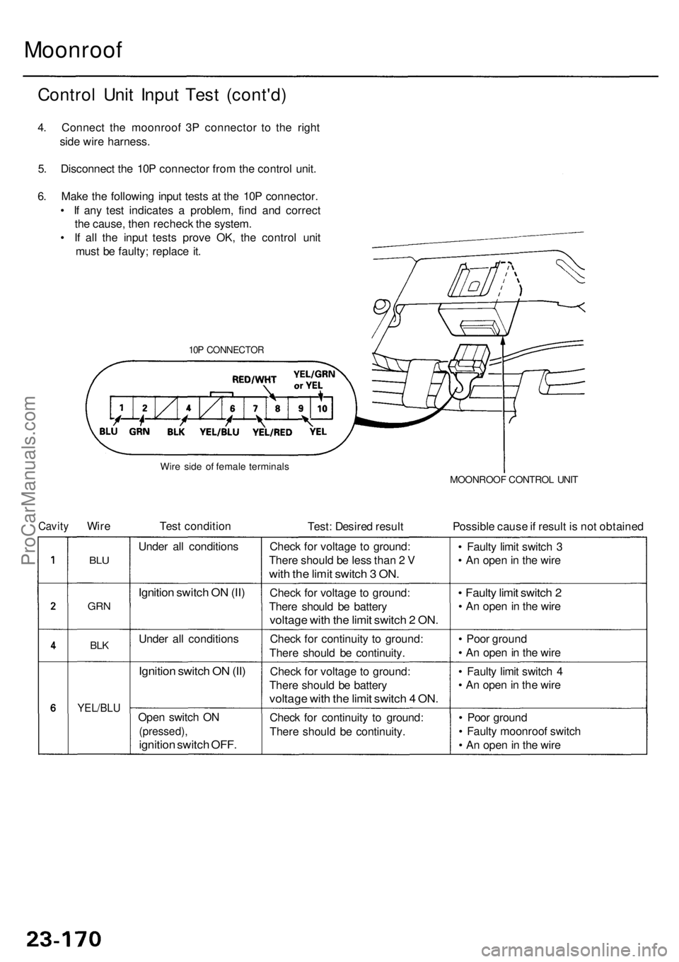
4. Connec t th e moonroo f 3 P connecto r t o th e righ t
sid e wir e harness .
5 . Disconnec t th e 10 P connecto r fro m th e contro l unit .
6 . Mak e th e followin g inpu t test s a t th e 10 P connector .
• I f an y tes t indicate s a problem , fin d an d correc t
th e cause , the n rechec k th e system .
• I f al l th e inpu t test s prov e OK , th e contro l uni t
mus t b e faulty ; replac e it .
Moonroo f
10P CONNECTO R
MOONROOF CONTRO L UNI T
Possibl e caus e if resul t i s no t obtaine d
Test : Desire d resul t
Tes
t conditio n
Wir eCavit y
Wire sid e o f femal e terminal s
BLU
GR N
BLK
YEL/BL U
Under al l condition s
Ignition switc h O N (II )
Unde r al l condition s
Ignition switc h O N (II )
Ope n switc h O N
(pressed) ,
ignition switc h OFF .
Chec k fo r continuit y t o ground :
Ther e shoul d b e continuity .
Chec
k fo r voltag e t o ground :
Ther e shoul d b e batter y
voltage wit h th e limi t switc h 4 ON .
Chec k fo r continuit y t o ground :
Ther e shoul d b e continuity .
Chec
k fo r voltag e t o ground :
Ther e shoul d b e batter y
voltage wit h th e limi t switc h 2 ON .
Chec k fo r voltag e t o ground :
Ther e shoul d b e les s tha n 2 V
wit h th e limi t switc h 3 ON .
• Poo r groun d
• Fault y moonroo f switc h
• A n ope n in th e wir e
•
Fault y limi t switc h 4
• A n ope n in th e wir e
•
Poo r groun d
• A n ope n in th e wir e
• Fault y limi t switc h 2
• A n ope n in th e wir e
•
Fault y limi t switc h 3
• A n ope n in th e wir e
ProCarManuals.com
Page 1583 of 1954
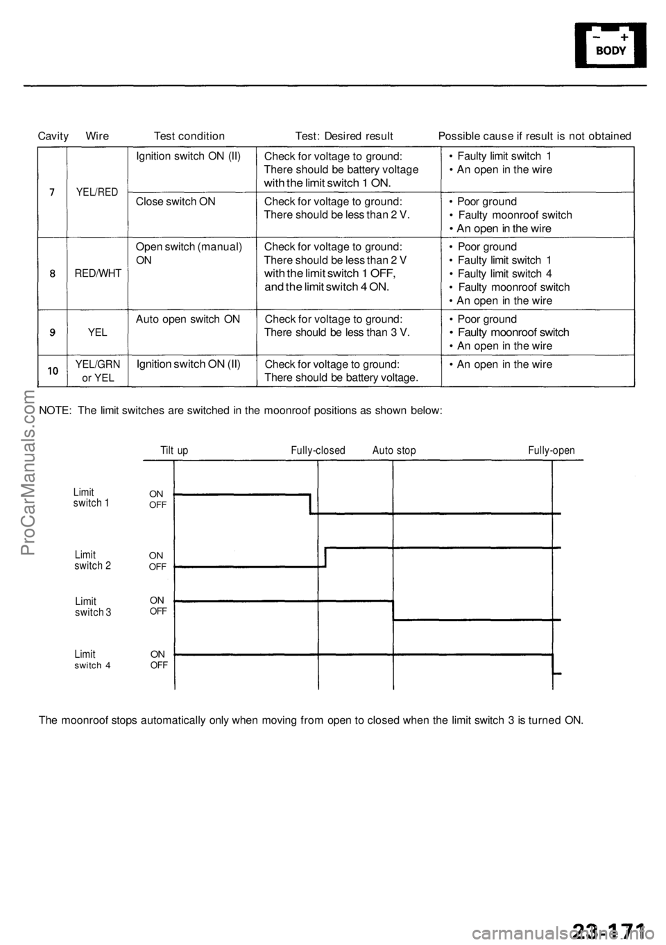
YEL/RED
Cavity Wire Test condition Test: Desired result Possible cause if result is not obtained
Ignition switch ON (II)
Close switch ON
Open switch (manual)
ON
RED/WHT
YEL
Auto open switch ON
Ignition switch ON (II)
YEL/GRN
or YEL
NOTE: The limit switches are switched in the moonroof positions as shown below:
Check for voltage to ground:
There should be battery voltage
with the limit switch 1 ON.
Check for voltage to ground:
There should be less than 2 V.
Check for voltage to ground:
There should be less than 2 V
with the limit switch 1 OFF,
and the limit switch 4 ON.
Check for voltage to ground:
There should be less than 3 V.
Check for voltage to ground:
There should be battery voltage.
• Faulty limit switch 1
• An open in the wire
• Poor ground
• Faulty moonroof switch
• An open in the wire
• Poor ground
• Faulty limit switch 1
• Faulty limit switch 4
• Faulty moonroof switch
• An open in the wire
• Poor ground
• Faulty moonroof switch
• An open in the wire
• An open in the wire
Tilt up Fully-closed Auto stop Fully-open
The moonroof stops automatically only when moving from open to closed when the limit switch 3 is turned ON.
Limit
switch 1
Limit
switch 2
Limit
switch 3
Limit
switch 4
ON
OFF
ON
OFF
ON
OFF
ON
OFFProCarManuals.com
Page 1593 of 1954
Description
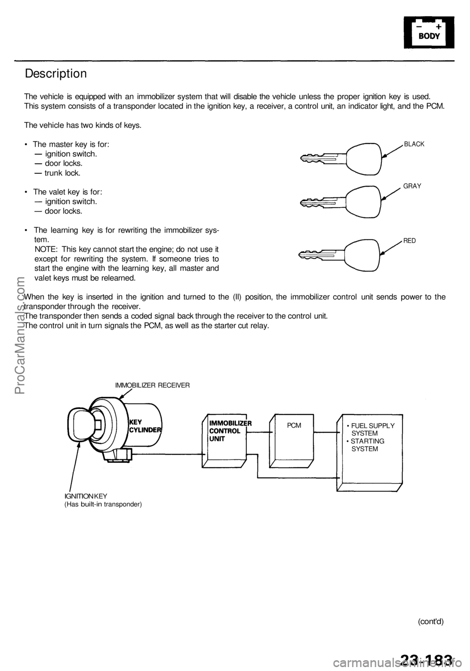
The vehicl e is equippe d wit h a n immobilize r syste m tha t wil l disabl e th e vehicl e unles s th e prope r ignitio n ke y i s used .
Thi s syste m consist s o f a transponde r locate d in th e ignitio n key , a receiver , a contro l unit , a n indicato r light , an d th e PCM .
Th e vehicl e ha s tw o kind s o f keys .
• Th e maste r ke y i s for :
ignitio n switch .
door locks .
trunk lock .
• Th e vale t ke y i s for :
ignitio n switch .
door locks .
• Th e learnin g ke y i s fo r rewritin g th e immobilize r sys -
tem.
NOTE : Thi s ke y canno t star t th e engine ; d o no t us e it
excep t fo r rewritin g th e system . I f someon e trie s t o
star t th e engin e wit h th e learnin g key , al l maste r an d
vale t key s mus t b e relearned .
Whe n th e ke y i s inserte d i n th e ignitio n an d turne d t o th e (II ) position , th e immobilize r contro l uni t send s powe r t o th e
transponde r throug h th e receiver .
Th e transponde r the n send s a code d signa l bac k throug h th e receive r t o th e contro l unit .
Th e contro l uni t i n tur n signal s th e PCM , a s wel l a s th e starte r cu t relay .
IMMOBILIZE R RECEIVE R
IGNITION KEY(Ha s built-i n transponder ) •
FUE L SUPPL Y
SYSTE M
• STARTIN G
SYSTEM
PCM
BLAC K
GRAY
RED
(cont'd )
ProCarManuals.com
Page 1594 of 1954
Immobilizer Syste m
Descriptio n (cont'd )
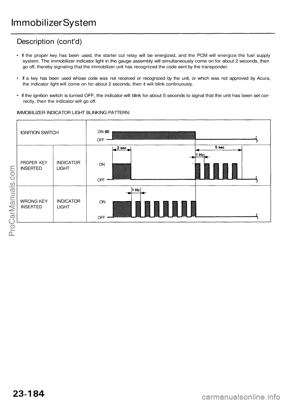
• I f th e prope r ke y ha s bee n used , th e starte r cu t rela y wil l b e energized , an d th e PC M wil l energiz e th e fue l suppl y
system . Th e immobilize r indicato r ligh t i n th e gaug e assembl y wil l simultaneousl y com e o n fo r abou t 2 seconds , the n
go off , thereb y signalin g tha t th e immobilize r uni t ha s recognize d th e cod e sen t b y th e transponder .
• I f a ke y ha s bee n use d whos e cod e wa s no t receive d o r recognize d b y th e unit , o r whic h wa s no t approve d b y Acura ,
th e indicato r ligh t wil l com e o n fo r abou t 2 seconds , the n it wil l blin k continuously .
• I f th e ignitio n switc h is turne d OFF , th e indicato r wil l blin k fo r abou t 5 second s to signa l tha t th e uni t ha s bee n se t cor -
rectly , the n th e indicato r wil l g o off .
IMMOBILIZE R INDICATO R LIGH T BLINKIN G PATTERN :
WRONG KE Y
INSERTE D
PROPER KE Y
INSERTE D
IGNITION SWITC H
INDICATO R
LIGHT
INDICATO R
LIGHT
ON
OF F
ON
OF F
ON
OF F
ProCarManuals.com
Page 1598 of 1954
Immobilizer Receive r Replacemen t
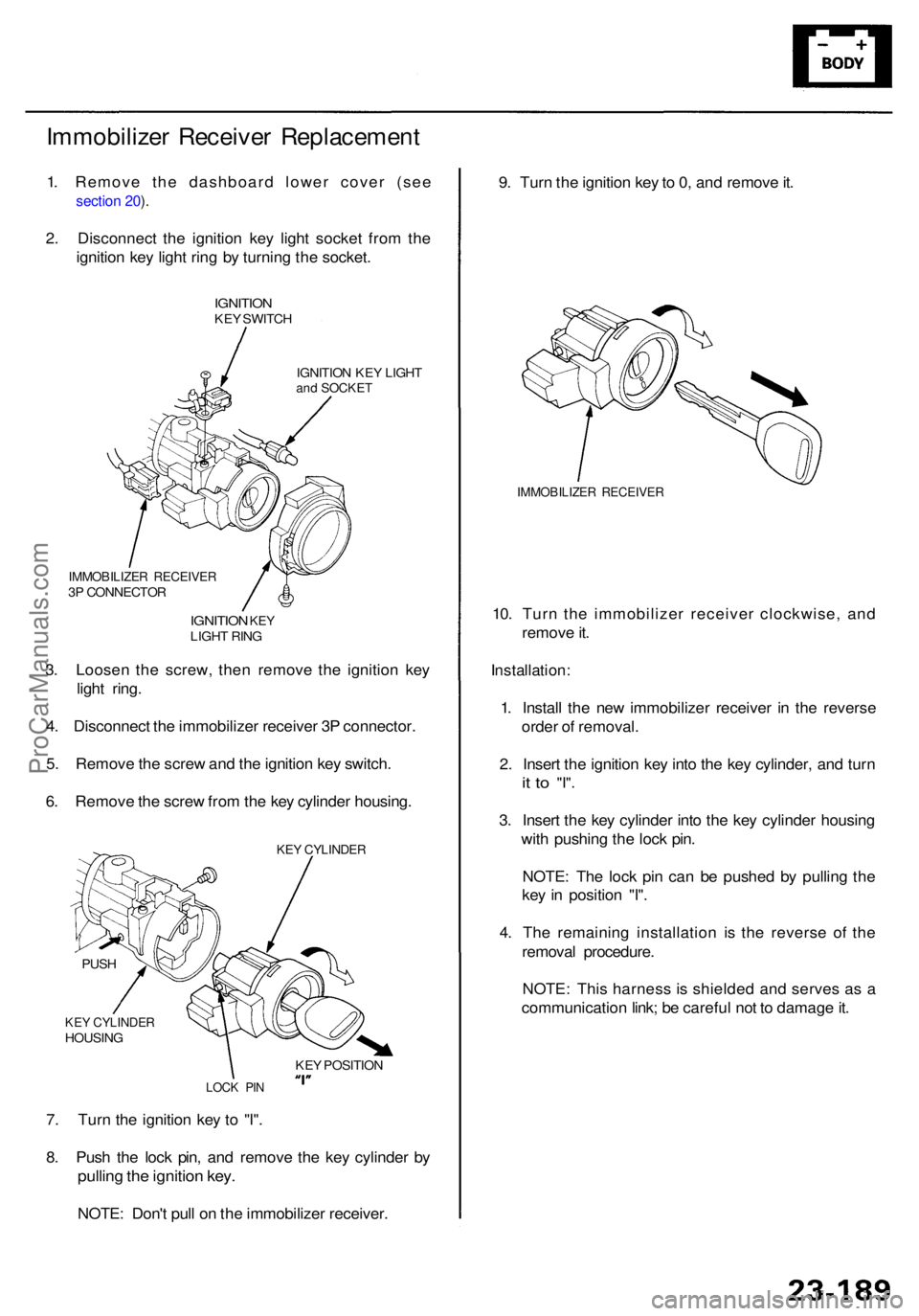
1. Remove the dashboard lower cover (see
section 20 ).
2 . Disconnec t th e ignitio n ke y ligh t socke t fro m th e
ignitio n ke y ligh t rin g b y turnin g th e socket .
IGNITIO NKEY SWITC H
IGNITIO N KE Y LIGH T
and SOCKE T
9. Tur n th e ignitio n ke y to 0, an d remov e it .
IMMOBILIZE R RECEIVE R
10. Tur n th e immobilize r receive r clockwise , an d
remov e it .
Installation :
1. Instal l th e ne w immobilize r receive r i n th e revers e
orde r o f removal .
2 . Inser t th e ignitio n ke y int o th e ke y cylinder , an d tur n
it t o "I" .
3. Inser t th e ke y cylinde r int o th e ke y cylinde r housin g
wit h pushin g th e loc k pin .
NOTE : Th e loc k pi n ca n b e pushe d b y pullin g th e
ke y i n positio n "I" .
4 . Th e remainin g installatio n i s th e revers e o f th e
remova l procedure .
NOTE : Thi s harnes s i s shielde d an d serve s a s a
communicatio n link ; b e carefu l no t t o damag e it .
7 . Tur n th e ignitio n ke y t o "I" .
8 . Pus h th e loc k pin , an d remov e th e ke y cylinde r b y
pullin g th e ignitio n key .
NOTE : Don' t pul l o n th e immobilize r receiver .
3
. Loose n th e screw , the n remov e th e ignitio n ke y
ligh t ring .
4 . Disconnec t th e immobilize r receive r 3 P connector .
5 . Remov e th e scre w an d th e ignitio n ke y switch .
6 . Remov e th e scre w fro m th e ke y cylinde r housing .
IMMOBILIZE R RECEIVE R3P CONNECTO R
IGNITION KEYLIGH T RIN G
KEY CYLINDE RHOUSING
PUS
H
LOC K PI N
KEY POSITIO N
KEY CYLINDE R
ProCarManuals.com