1996 ACURA RL KA9 ignition
[x] Cancel search: ignitionPage 802 of 1954

18. Install the control lever.
CAUTION: Take care not to bend the shift cable.
SPRING
WASHER
CONTROL SHAFT
19. Connect the shift solenoid valve/A/T clutch pressure
control solenoid valve harness connector.
20. Install the shift solenoid valve/A/T clutch pressure
control solenoid valve harness clamp to the shift
cable cover, then install the shift cable cover onto
the transmission.
CLAMP
SHIFT CABLE
COVER
SHIFT SOLENOID VALVE/
A/T CLUTCH PRESSURE
CONTROL SOLENOID VALVE
HARNESS CONNECTOR
21. Connect the transmission range switch harness
connector, then clamp the harness clamp on the
brackets.
22. Turn the ignition switch ON (II). Move the shift lever
through all gears, and check the transmission range
switch synchronization with the A/T gear position
indicator.
GAUGE ASSEMBLY
A/T GEAR POSITION
INDICATOR
23. If the transmission range switch is not synchronized
with the A/T gear position indicator, loosen the bolts
securing the transmission range switch and adjust
the transmission range switch installation.
24. Start the engine. Move the shift lever through all
gears, and verify the following:
• The shift lever cannot be moved to the position
from the position without pushing the shift
lever.
• The engine will not start in any drive gear, only in
the or position.
• The back-up lights come on when the shift lever is
in the position.
8 x
1.25
mm
16 N-m (1.6 kgf-m, 12 Ibf-ft)
CONTROL
LEVER
6 x 1.0 mm
12 N-m (1.2 kgf-m,
8.7 Ibf-ft)ProCarManuals.com
Page 987 of 1954

Inspection
• Fo r tilt/extend-retrac t motor s an d sensor s inspection ,
refe r t o th e Drivin g Positio n Memor y Syste m (DPMS )
i n th e sectio n 23 .
• Chec k th e steerin g colum n bai l bearin g an d th e steerin g
join t bearing s fo r pla y an d prope r movement . I f ther e is
nois y o r i f ther e is excessiv e play , replac e th e steerin g
colum n a s a n assembly .
• Chec k th e retainin g collar s fo r damage . I f the y ar e dam -
aged , replac e th e retainin g collars .
• Chec k th e absorbin g plates , absorbin g plat e guide s
an d slidin g capsule s fo r distortio n an d breakage .
Replac e th e steerin g colum n a s a n assembl y i f the y
are distorte d o r broken .
ABSORBIN G PLATE S
COLUMN BAL L BEARIN G
ABSORBIN G PLAT E GUIDE S
STEERIN G JOIN TBEARING S
PLASTICINJECTION S
IGNITION SWITC HSee sectio n 23 .
SLIDIN G CAPSUL EThis par t i s attache dto th e colum n bracke twith th e plasti c injections .
RETAININ G COLLAR S
ProCarManuals.com
Page 988 of 1954
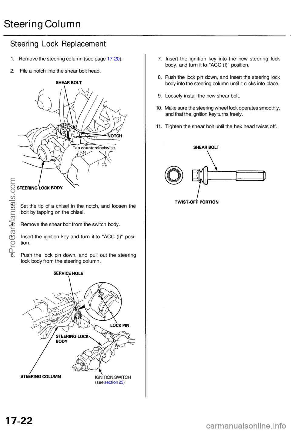
Steering Loc k Replacemen t
1. Remov e th e steerin g colum n (se e pag e 17-20 ).
2 . Fil e a notc h int o th e shea r bol t head .
Steerin g Colum n
7. Inser t th e ignitio n ke y int o th e ne w steerin g loc k
body , an d tur n it t o "AC C (I) " position .
8 . Pus h th e loc k pi n down , an d inser t th e steerin g loc k
bod y int o th e steerin g colum n unti l i t click s int o place .
9 . Loosel y instal l th e ne w shea r bolt .
10 . Mak e sur e th e steerin g whee l loc k operate s smoothly ,
an d tha t th e ignitio n ke y turn s freely .
11 . Tighte n th e shea r bol t unti l th e he x hea d twist s off .
3 . Se t th e ti p o f a chise l i n th e notch , an d loose n th e
bol t b y tappin g o n th e chisel .
4 . Remov e th e shea r bol t fro m th e switc h body .
5 . Inser t th e ignitio n ke y an d tur n i t t o "AC C (I) " posi -
tion.
6. Pus h th e loc k pi n down , an d pul l ou t th e steerin g
loc k bod y fro m th e steerin g column .
IGNITION SWITC H(see sectio n 23 )
ProCarManuals.com
Page 1087 of 1954
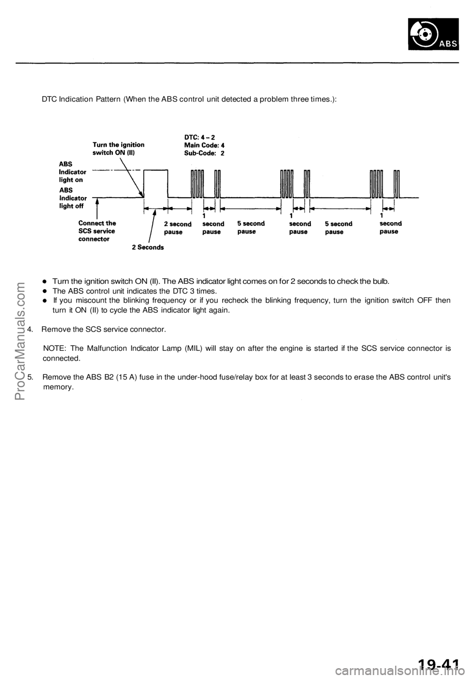
DTC Indication Pattern (When the ABS control unit detected a problem three times.):
Turn the ignition switch ON (II). The ABS indicator light comes on for 2 seconds to check the bulb.
The ABS control unit indicates the DTC 3 times.
If you miscount the blinking frequency or if you recheck the blinking frequency, turn the ignition switch OFF then
turn it ON (II) to cycle the ABS indicator light again.
4. Remove the SCS service connector.
NOTE: The Malfunction Indicator Lamp (MIL) will stay on after the engine is started if the SCS service connector is
connected.
5. Remove the ABS B2 (15 A) fuse in the under-hood fuse/relay box for at least 3 seconds to erase the ABS control unit's
memory.ProCarManuals.com
Page 1154 of 1954
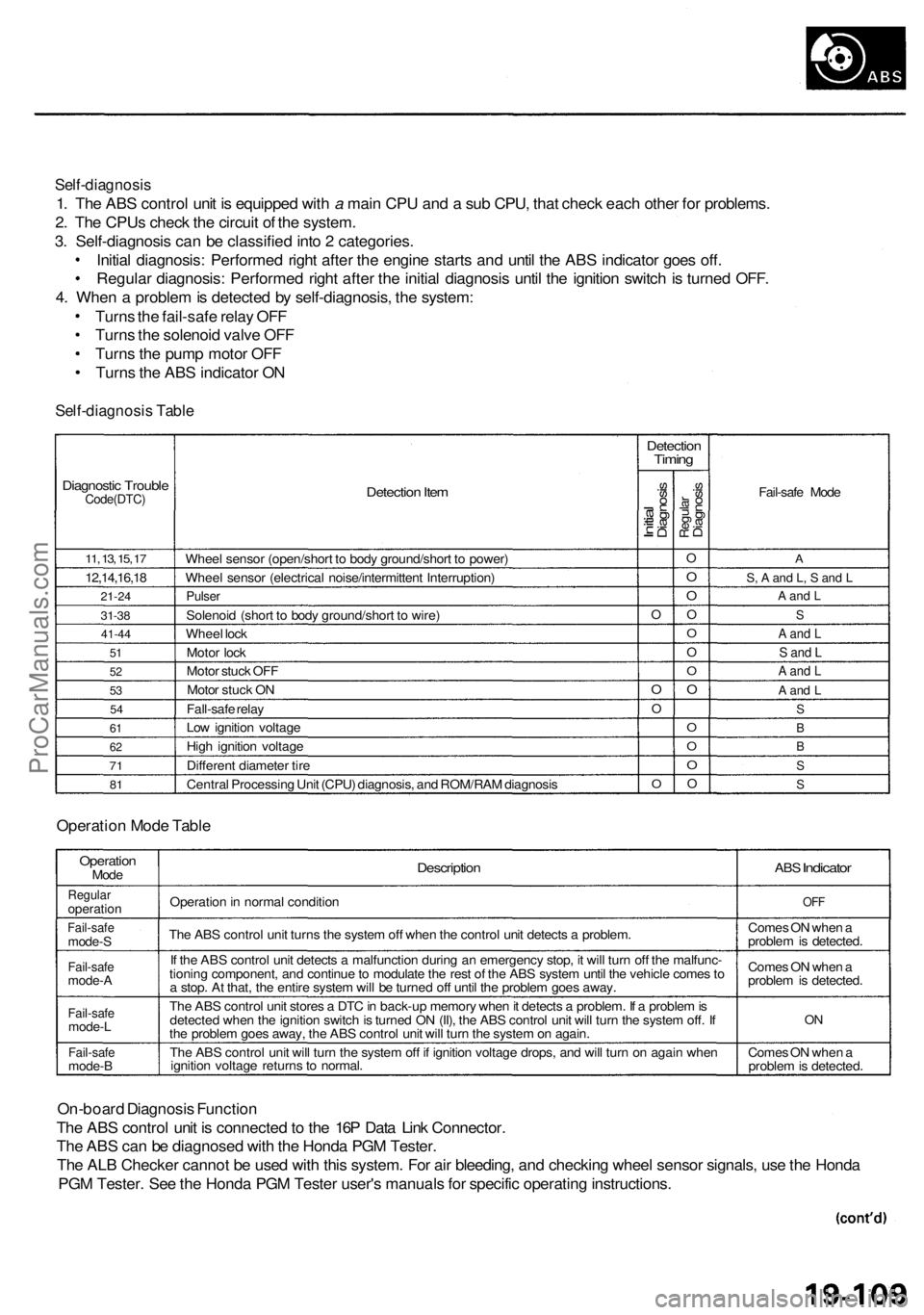
Self-diagnosis
1. The ABS control unit is equipped with a main CPU and a sub CPU, that check each other for problems.
2. The CPUs check the circuit of the system.
3. Self-diagnosis can be classified into 2 categories.
Initial diagnosis: Performed right after the engine starts and until the ABS indicator goes off.
Regular diagnosis: Performed right after the initial diagnosis until the ignition switch is turned OFF.
4. When a problem is detected by self-diagnosis, the system:
Turns the fail-safe relay OFF
Turns the solenoid valve OFF
Turns the pump motor OFF
Turns the ABS indicator ON
Self-diagnosis Table
Diagnostic Trouble
Code(DTC)
11, 13, 15, 17
12,14,16,18
21-24
31-38
41-44
51
52
53
54
61
62
71
81
Detection Item
Wheel sensor (open/short to body ground/short to power)
Wheel sensor (electrical noise/intermittent Interruption)
Pulser
Solenoid (short to body ground/short to wire)
Wheel lock
Motor lock
Motor stuck OFF
Motor stuck ON
Fall-safe relay
Low ignition voltage
High ignition voltage
Different diameter tire
Central Processing Unit (CPU) diagnosis, and ROM/RAM diagnosis
Detection
Timing
Initial
Diagnosis
O
O
O
O
Regular
Diagnosis
O
O
O
O
O
O
O
O
O
O
O
O
Fail-safe Mode
A
S, A and L, S and L
A and L
S
A and L
S and L
A and L
A and L
S
B
B
S
S
Operation Mode Table
Operation
Mode
Regular
operation
Fail-safe
mode-S
Fail-safe
mode-A
Fail-safe
mode-L
Fail-safe
mode-B
Description
Operation in normal condition
The ABS control unit turns the system off when the control unit detects a problem.
If the ABS control unit detects a malfunction during an emergency stop, it will turn off the malfunc-
tioning component, and continue to modulate the rest of the ABS system until the vehicle comes to
a stop. At that, the entire system will be turned off until the problem goes away.
The ABS control unit stores a DTC in back-up memory when it detects a problem. If a problem is
detected when the ignition switch is turned ON (II), the ABS control unit will turn the system off. If
the problem goes away, the ABS control unit will turn the system on again.
The ABS control unit will turn the system off if ignition voltage drops, and will turn on again when
ignition voltage returns to normal.
ABS
Indicator
OFF
Comes ON when a
problem is detected.
Comes ON when a
problem is detected.
ON
Comes ON when a
problem is detected.
On-board Diagnosis Function
The ABS control unit is connected to the 16P Data Link Connector.
The ABS can be diagnosed with the Honda PGM Tester.
The ALB Checker cannot be used with this system. For air bleeding, and checking wheel sensor signals, use the Honda
PGM Tester. See the Honda PGM Tester user's manuals for specific operating instructions.
ProCarManuals.com
Page 1157 of 1954
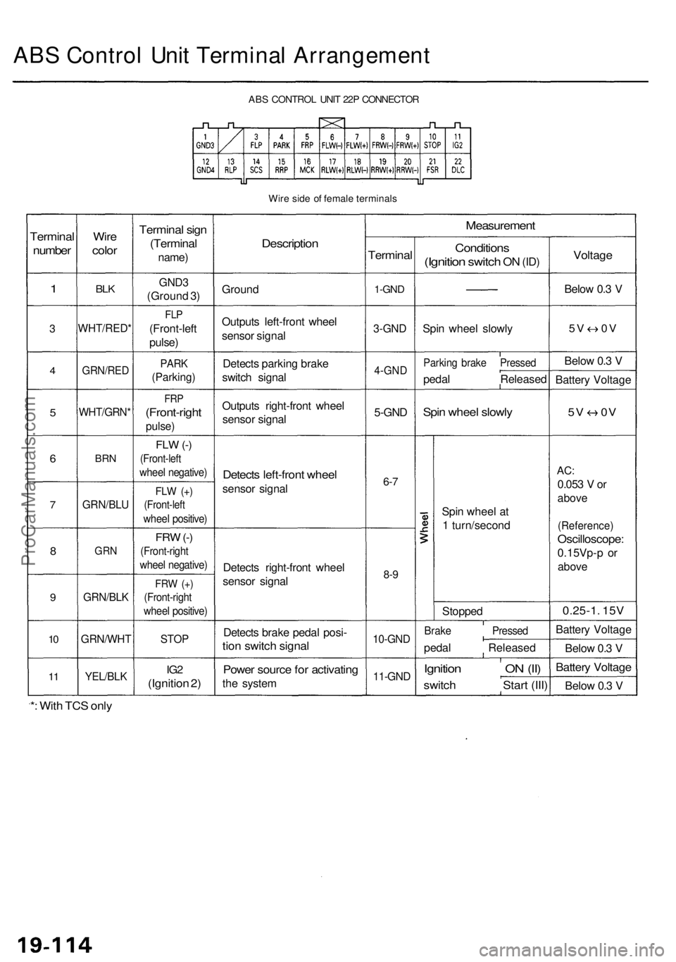
ABS Contro l Uni t Termina l Arrangemen t
ABS CONTRO L UNI T 22 P CONNECTO R
Wir e sid e o f femal e terminal s
Terminal
number
1
3
4
5
6
7
8
9
10
1 1
Wir e
colo r
BLK
WHT/RED *
GRN/RED
WHT/GRN *
BRN
GRN/BL U
GRN
GRN/BL K
GRN/WH T
YEL/BLK
Termina l sig n
(Termina l
name)
GND3
(Groun d 3 )
FL P
(Front-lef t
pulse )
PARK
(Parking )
FRP
(Front-righ t
pulse)
FLW (-)
(Front-lef t
wheel negative )
FLW (+ )
(Front-lef t
wheel positive )
FRW (-)
(Front-righ t
wheel negative )
FRW (+ )
(Front-righ t
wheel positive )
STOP
IG2
(Ignitio n 2 )
Descriptio n
Ground
Output s left-fron t whee l
senso r signa l
Detect s parkin g brak e
switc h signa l
Output s right-fron t whee l
senso r signa l
Detect s left-fron t whee l
senso r signa l
Detect s right-fron t whee l
senso r signa l
Detect s brak e peda l posi -
tion switc h signa l
Power sourc e fo r activatin g
the syste m
Measuremen t
Terminal
1-GND
3-GN D
4-GN D
5-GND
6-7
8- 9
10-GN D
11-GND
Condition s
(Ignition switch ON (ID )
Spi n whee l slowl y
Parkin g brak e Presse d
pedal Release d
Spin whee l slowl y
Spin whee l a t
1 turn/secon d
Stoppe d
Brake Presse d
pedal Release d
Ignition O N (II )
switc h Star t (III )
Voltag e
Below 0. 3 V
5 V 0 V
Below 0. 3 V
Batter y Voltag e
5V 0 V
AC:
0.05 3 V or
abov e
(Reference )
Oscilloscope :
0.15Vp-p o r
abov e
0.25-1 . 15 V
Batter y Voltag e
Belo w 0. 3 V
Batter y Voltag e
Below 0. 3 V
*: Wit h TC S onl y
ProCarManuals.com
Page 1158 of 1954
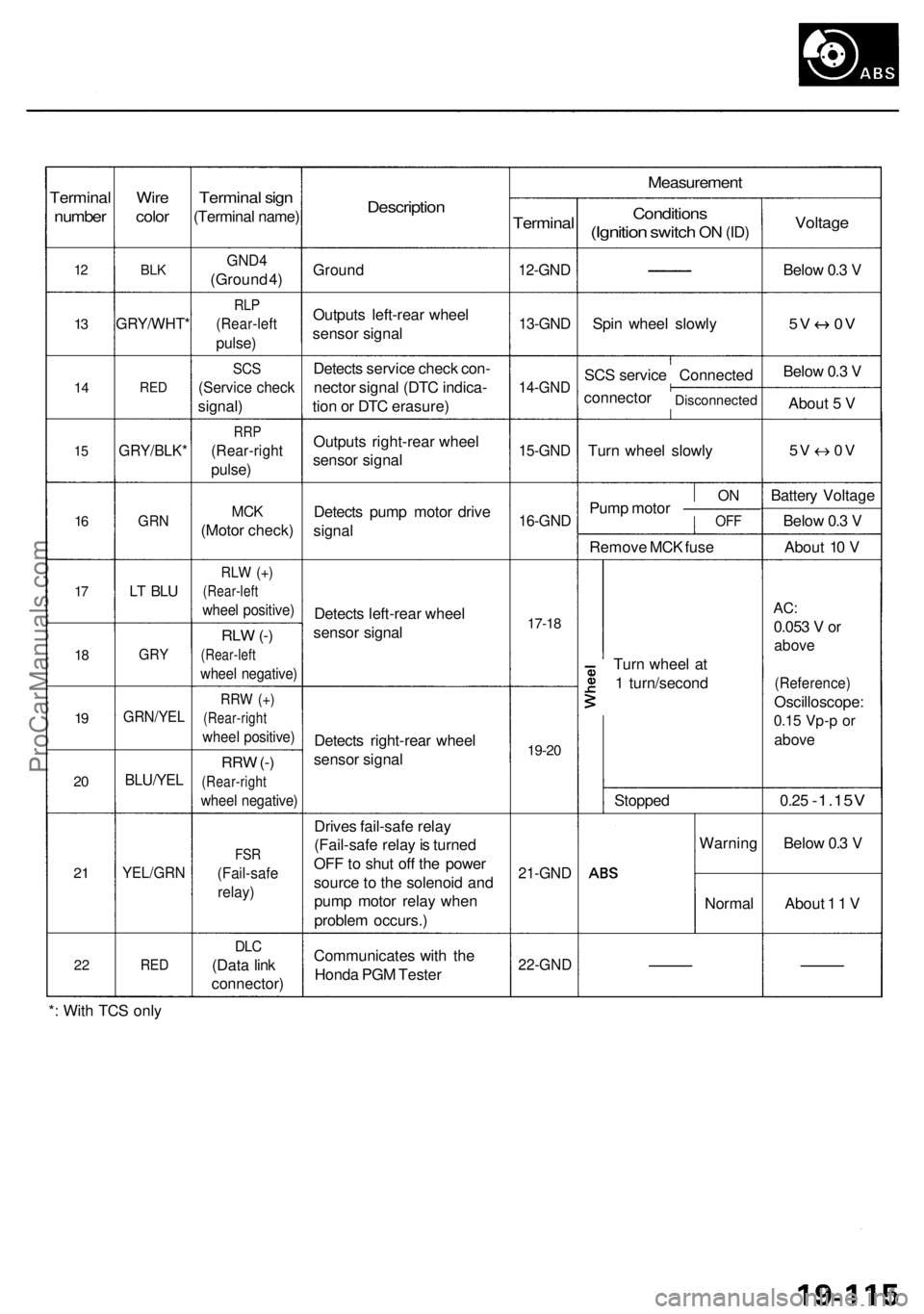
Terminal
number
12
13
1 4
15
16
17
1 8
19
2 0
2 1
2 2
Wir e
colo r
BLK
GRY/WHT *
RED
GRY/BLK *
GRN
LT BL U
GR Y
GRN/YE L
BLU/YEL
YEL/GR N
RED
Termina l sig n
(Termina l name )
GND4
(Groun d 4 )
RL P
(Rear-lef t
pulse)
SCS
(Servic e chec k
signal )
RRP
(Rear-righ t
pulse)
MCK
(Moto r check )
RLW (+ )
(Rear-lef t
wheel positive )
RLW (-)
(Rear-lef t
wheel negative )
RRW (+ )
(Rear-righ t
wheel positive )
RRW (-)
(Rear-righ t
wheel negative )
FSR
(Fail-saf e
relay)
DLC
(Dat a lin k
connector )
Description
Ground
Output s left-rea r whee l
senso r signa l
Detect s servic e chec k con -
necto r signa l (DT C indica -
tio n o r DT C erasure )
Output s right-rea r whee l
senso r signa l
Detect s pum p moto r driv e
signa l
Detect s left-rea r whee l
senso r signa l
Detect s right-rea r whee l
senso r signa l
Drive s fail-saf e rela y
(Fail-saf e rela y is turne d
OF F to shu t of f th e powe r
sourc e to th e solenoi d an d
pum p moto r rela y whe n
proble m occurs. )
Communicate s wit h th e
Hond a PG M Teste r
Measuremen t
Terminal
12-GND
13-GND
14-GN D
15-GND
16-GND
17-18
19-2 0
21-GN D
22-GN D
Condition s
(Ignition switch ON (ID )
Spi n whee l slowl y
SC S servic e Connecte d
connecto r
Disconnecte d
Turn whee l slowl y
ONPum p moto r —————OF F
Remov e MC K fus e
Tur n whee l a t
1 turn/secon d
Stoppe d
Warnin g
Norma l
Voltage
Below 0. 3 V
5 V 0 V
Below 0. 3 V
Abou t 5 V
5V 0 V
Batter y Voltag e
Belo w 0. 3 V
Abou t 1 0 V
AC :
0.05 3 V or
abov e
(Reference )
Oscilloscope :
0.15 Vp- p o r
abov e
0.25 -1.15 V
Below 0. 3 V
Abou t 1 1 V
* : Wit h TC S onl y
ProCarManuals.com
Page 1159 of 1954
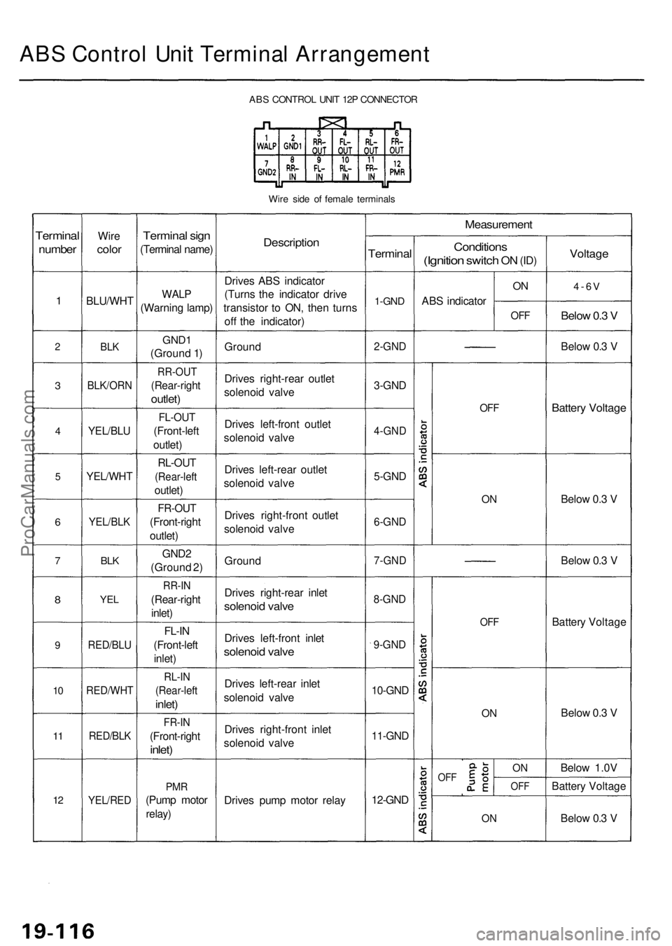
ABS Contro l Uni t Termina l Arrangemen t
ABS CONTRO L UNI T 12 P CONNECTO R
Wir e sid e o f femal e terminal s
Terminal
number
1
2
3
4
5
6
7
8
9
10
1 1
12
Wir e
colo r
BLU/WH T
BLK
BLK/OR N
YEL/BLU
YEL/WH T
YEL/BLK
BLK
YE L
RED/BL U
RED/WH T
RED/BLK
YEL/RE D
Terminal sig n
(Termina l name )
WALP
(Warnin g lamp )
GND1
(Groun d 1 )
RR-OU T
(Rear-righ t
outlet)
FL-OU T
(Front-lef t
outlet )
RL-OU T
(Rear-lef t
outlet)
FR-OU T
(Front-righ t
outlet )
GND 2
(Groun d 2 )
RR-I N
(Rear-righ t
inlet )
FL-I N
(Front-lef t
inlet )
RL-I N
(Rear-lef t
inlet)
FR-I N
(Front-righ t
inlet)
PMR
(Pum p moto r
relay)
Descriptio n
Drives AB S indicato r
(Turn s th e indicato r driv e
transisto r t o ON , the n turn s
of f th e indicator )
Groun d
Drive s right-rea r outle t
solenoi d valv e
Drive s left-fron t outle t
solenoi d valv e
Drive s left-rea r outle t
solenoi d valv e
Drive s right-fron t outle t
solenoi d valv e
Groun d
Drive s right-rea r inle t
solenoi d valv e
Drive s left-fron t inle t
solenoi d valv e
Drive s left-rea r inle t
solenoi d valv e
Drive s right-fron t inle t
solenoi d valv e
Drive s pum p moto r rela y
Measuremen t
Terminal
1-GND
2-GN D
3-GND
4-GN D
5-GND
6-GN D
7-GN D
8-GND
9-GND
10-GN D
11-GND
12-GND
Condition s
(Ignition switch ON (ID )
AB S indicato r
ON
OF F
OFF
ON
OF F
ON
OF FON
OF F
ON
Voltag e
4-6V
Below 0. 3 V
Belo w 0. 3 V
Batter y Voltag e
Below 0. 3 V
Belo w 0. 3 V
Batter y Voltag e
Belo w 0. 3 V
Belo w 1.0 V
Batter y Voltag e
Belo w 0. 3 V
ProCarManuals.com