1996 ACURA RL KA9 ignition
[x] Cancel search: ignitionPage 255 of 1954

- +
BODY
4. Turn the ignition switch OFF.
5. Disconnect the display unit connector B (20P).
6. Check for continuity between display unit connector
B (20P) terminal No. 10 and body ground.
DISPLAY UNIT CONNECTOR B (20P)
Wire side of female terminals
Is there continuity?
YES—Go to step 7.
NO—Repair the open in the wire between the display
unit and body ground (G251).
7. Disconnect the navigation unit connector A (20P).
8. Check for continuity between body ground and dis-
play unit connector B (20P) terminal No. 5 and No. 15
individually.
DISPLAY UNIT CONNECTOR B (20P)
DISP BUS {+)
(BLK)
Wire side of female terminals
Is there continuity?
YES—There is a short to body ground in the circuit
between the display unit and the navigation unit.
Replace the affected shielded harness.
NO—Go to step 9.
9. Check for continuity between display unit connector
B (20P) terminal No. 5 and navigation unit connector
A (20P) terminal No. 10.
DISPLAY UNIT CONNECTOR B (20P)
DISP BUS {+} (BLK)
Wire side of female terminals
Is there continuity?
YES—Go to step 10.
NO—There is an open in the circuit between the dis-
play unit and the navigation unit. Check for poor con-
nections or loose terminals at the display and naviga-
tion units. If a poor connection or loose terminal is
found, replace the affected shielded harness.
(cont'd)ProCarManuals.com
Page 264 of 1954

+
BODY
Navigatio n Stay s o n wit h ignitio n switc h of f
NOTE :
• Alway s chec k th e connector s fo r poo r connection s o r
loos e terminals .
• Befor e troubleshooting , ge t th e navigatio n syste m
anti-thef t codes .
• Afte r troubleshooting , re-ente r th e anti-thef t code ,
an d re-initializ e th e navigatio n system .
1. Wit h th e ke y ou t o f ignition .
Does the navigation screen stay on?
YES—G o to ste p 2 .
NO—Th e syste m is O K a t thi s time .
2 . Th e ca r ma y hav e bee n use d a s a demonstratio n
vehicl e a t a n even t lik e a n aut o show . I n thes e events ,
powe r i s ofte n jumpere d t o th e navigatio n syste m s o
tha t th e ignitio n ke y i s no t neede d i n th e vehicle . A t
th e en d o f th e show , th e jumpe r wir e ma y no t hav e
bee n removed . Chec k th e navigatio n uni t "C " con -
necto r (8P ) fo r a "non-factory " jumpe r wir e in serie s
wit h th e factor y cable .
Is there jumper wire?
YES—Remov e th e jumpe r wire , an d re-test .
NO—G o t o ste p 3 . 3
. Th e displa y o r audi o uni t ma y hav e bee n jumpere d
behin d th e das h t o allo w th e navigatio n syste m to
ru n withou t th e ignitio n key .
Doe s the radio function with the ignition switch off?
YES—G o to ste p 4 .
NO—G o t o ste p 5 .
4 . Remov e th e displa y uni t an d chec k t o se e if th e audi o
uni t connector s hav e a non-factor y jumpe r wir e i n
serie s wit h th e factor y connector .
Is there a jumper wire?
YES—Remov e th e jumpe r wire , an d re-test .
NO—G o to ste p 5 .
5. Chec k th e interio r light s wit h th e ignitio n switc h off .
Can you turn on the interior lights with the ignition
switch off?
YES—Troubleshoo t the AC C circuit .
NO—Replac e th e navigatio n uni t
(se e pag e 23-53 ).
23-3 9
ProCarManuals.com
Page 337 of 1954

Ignition Syste m
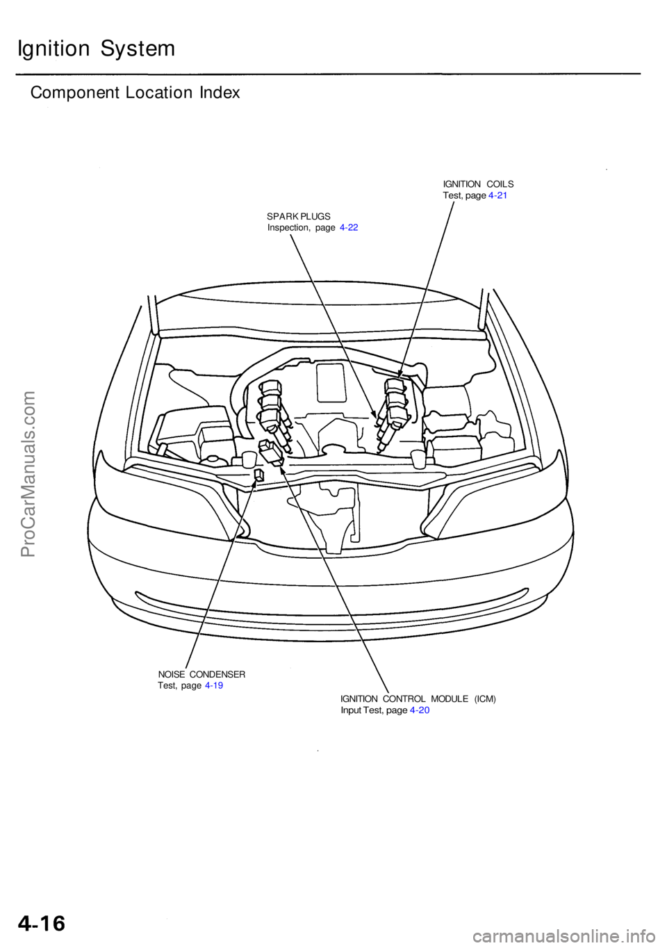
Componen t Locatio n Inde x
IGNITIO N COIL STest, pag e 4-2 1
SPAR K PLUG S
Inspection , pag e 4-2 2
NOIS E CONDENSE R
Test , pag e 4-1 9
IGNITION CONTRO L MODUL E (ICM )
Input Test , pag e 4-2 0
ProCarManuals.com
Page 338 of 1954

Ignition Syste m
Ignition Timin g Inspectio n
SRS component s ar e locate d in thi s area . Revie w th e SR S
componen t locations , precautions , an d procedure s i n th e
SR S (sectio n 24 ) befor e performin g repair s o r service .
1 . Star t th e engine . Hol d th e engin e a t 3,00 0 rp m wit h
no loa d (shif t leve r i n o r position ) unti l th e
radiato r fa n come s on , the n le t i t idle .
2 . Pul l ou t th e servic e chec k connecto r locate d unde r
th e glov e box . Connec t th e GRN/BL K an d RE D wir e
terminal s wit h th e specia l tool .
SERVIC E CHEC K CONNECTO R (2P )
NOTE : Locate d unde r th e glov e bo x
SC S SERVIC E CONNECTO R
(07PAZ-0010100 )
3. Chec k th e idl e spee d (se e pag e 4-19 ).
4 . Remov e th e engin e cove r (se e sectio n 5 ).
5 . Connec t a timin g ligh t t o th e No . 1 ignitio n coi l wires ;
while th e engin e idles , poin t th e timin g ligh t towar d
the pointe r o n th e timin g bel t cover .
No. 1 IGNITIO NCOIL WIRE S
TIMING LIGH T
CRANKSHAF T PULLE Y
6. Inspec t ignitio n timin g a t idl e speed .
Ignitio n Timing :
1 5 ± 2° BTD C (RED ) a t 65 0 ± 5 0 rp m wit h shif t leve r
in o r positio n an d electrica l system s turne d
off.
WHIT E MAR K
POINTER
CRANKSHAF T PULLE Y
RED MAR K
7. I f th e ignitio n timin g i s incorrect , replac e th e PC M
(ther e i s n o wa y t o adjus t ignitio n timing) .
8 . Disconnec t th e specia l too l fro m th e servic e chec k
connecto r (2P) .
ProCarManuals.com
Page 340 of 1954

Ignition Syste m
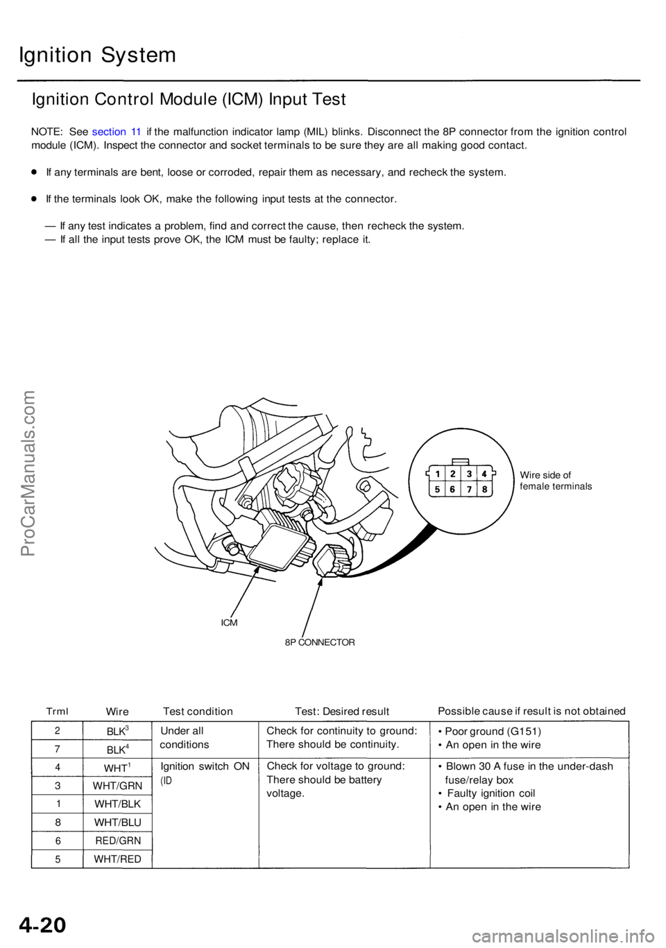
Ignition Contro l Modul e (ICM ) Inpu t Tes t
NOTE : Se e sectio n 1 1 i f th e malfunctio n indicator lamp (MIL ) blinks . Disconnec t th e 8 P connecto r fro m th e ignitio n contro l
modul e (ICM) . Inspec t th e connecto r an d socke t terminal s t o b e sur e the y ar e al l makin g goo d contact .
I f an y terminal s ar e bent , loos e o r corroded , repai r the m a s necessary , an d rechec k th e system .
I f th e terminal s loo k OK , mak e th e followin g inpu t test s a t th e connector .
— If an y tes t indicate s a problem , fin d an d correc t th e cause , the n rechec k th e system .
— If al l th e inpu t test s prov e OK , th e IC M mus t b e faulty ; replac e it .
Wir e sid e o ffemal e terminal s
ICM
8P CONNECTO R
TrmlWire Tes
t conditio n Test: Desire d resul t Possibl
e caus e if resul t i s no t obtaine d
2
7
4
3
1
8
6
5
BLK3
BLK4
WHT1
WHT/GR N
WHT/BLK
WHT/BLU
RED/GR N
WHT/RED
Under al l
condition s
Ignitio n switc h O N
(ID
Chec k fo r continuit y t o ground :
Ther e shoul d b e continuity .
Chec k fo r voltag e t o ground :
Ther e shoul d b e batter y
voltage . •
Poo r groun d (G151 )
• A n ope n in th e wir e
• Blow n 3 0 A fus e in th e under-das h
fuse/rela y bo x
• Fault y ignitio n coi l
• A n ope n i n th e wir e
ProCarManuals.com
Page 341 of 1954

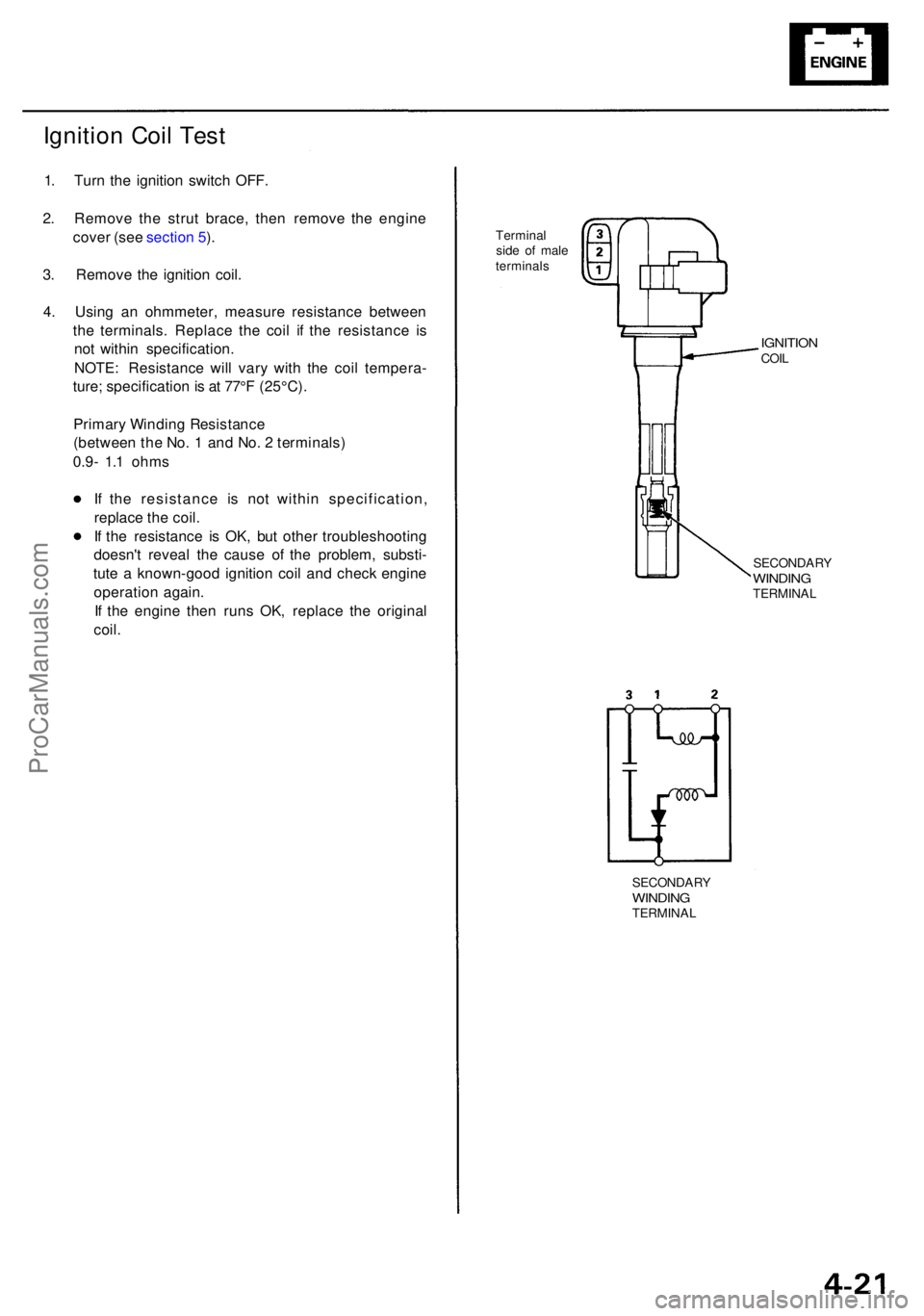
Ignition Coi l Tes t
1. Tur n th e ignitio n switc h OFF .
2 . Remov e th e stru t brace , the n remov e th e engin e
cove r (se e sectio n 5 ).
3 . Remov e th e ignitio n coil .
4 . Usin g a n ohmmeter , measur e resistanc e betwee n
th e terminals . Replac e th e coi l i f th e resistanc e i s
no t withi n specification .
NOTE : Resistanc e wil l var y wit h th e coi l tempera -
ture ; specificatio n is a t 77° F (25°C) .
Primar y Windin g Resistanc e
(betwee n th e No . 1 an d No . 2 terminals )
0.9- 1.1 ohm s
I f th e resistanc e i s no t withi n specification ,
replac e th e coil .
I f th e resistanc e i s OK , bu t othe r troubleshootin g
doesn' t revea l th e caus e o f th e problem , substi -
tut e a known-goo d ignitio n coi l an d chec k engin e
operatio n again .
I f th e engin e the n run s OK , replac e th e origina l
coil .
Termina l
sid e o f mal e
terminal s
IGNITIONCOIL
SECONDAR YWINDINGTERMINA L
SECONDAR YWINDINGTERMINA L
ProCarManuals.com
Page 342 of 1954

Ignition Syste m
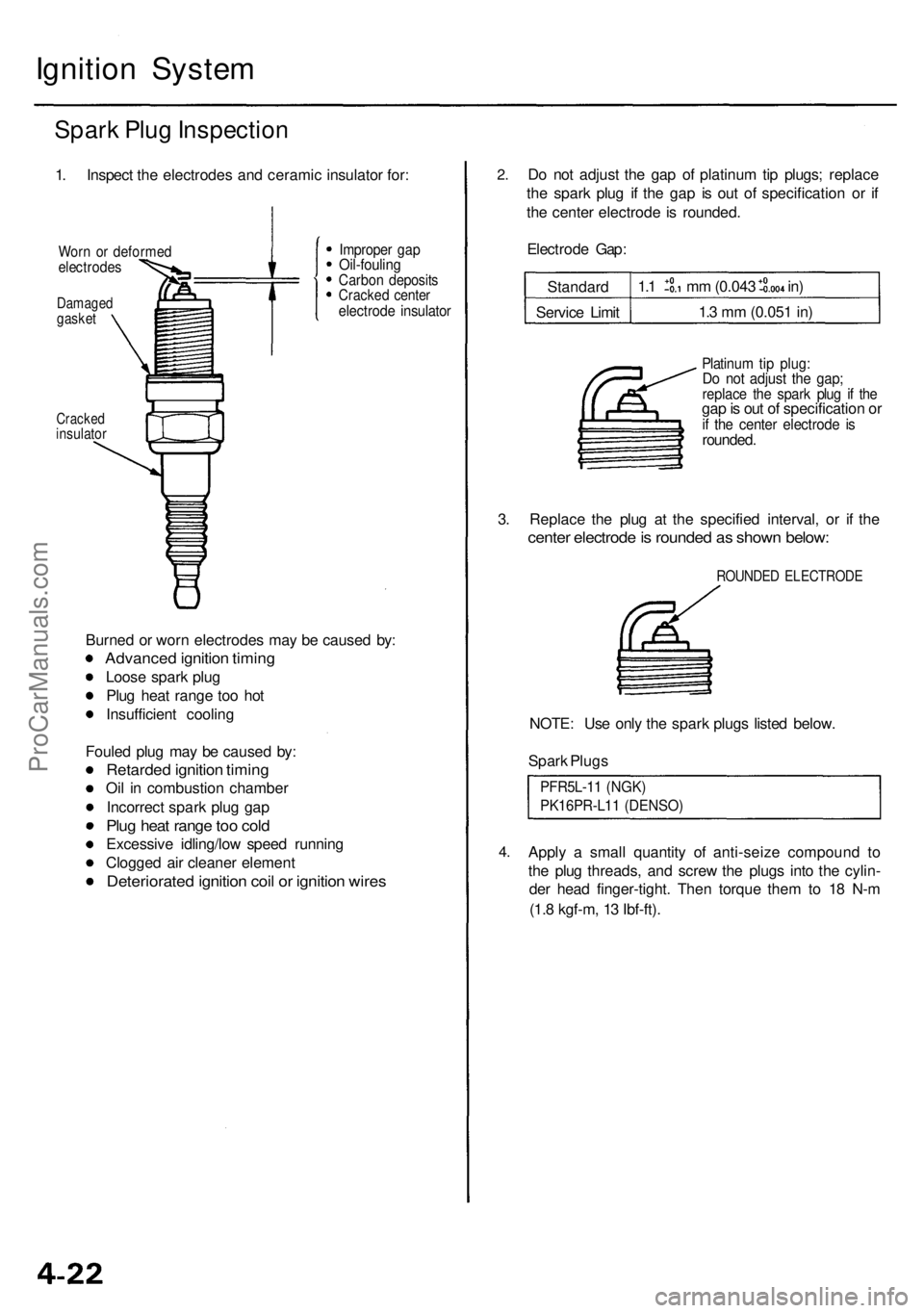
Spark Plu g Inspectio n
1. Inspec t th e electrode s an d cerami c insulato r for :
Wor n o r deforme delectrode s
Damagedgasket
Cracke dinsulato r
Improper ga pOil-foulin gCarbon deposit sCracked cente relectrod e insulato r
Burned o r wor n electrode s ma y b e cause d by :
Advance d ignitio n timin g
Loose spar k plu g
Plu g hea t rang e to o ho t
Insufficien t coolin g
Foule d plu g ma y b e cause d by :
Retarde d ignitio n timin g
Oil i n combustio n chambe r
Incorrec t spar k plu g ga p
Plug hea t rang e to o col d
Excessiv e idling/lo w spee d runnin g
Clogge d ai r cleane r elemen t
Deteriorate d ignitio n coi l o r ignitio n wire s
2.D o no t adjus t th e ga p o f platinu m ti p plugs ; replac e
th e spar k plu g i f th e ga p i s ou t o f specificatio n o r i f
th e cente r electrod e i s rounded .
Electrod e Gap :
Standar d
Servic e Limi t
1.1 m m (0.04 3 in )
1. 3 m m (0.05 1 in )
Platinu m tip plug :Do no t adjus t th e gap ;replac e th e spar k plu g i f th egap is ou t o f specificatio n o rif th e cente r electrod e i srounded .
3. Replac e th e plu g a t th e specifie d interval , o r i f th e
cente r electrod e is rounde d a s show n below :
ROUNDE D ELECTROD E
NOTE: Us e onl y th e spar k plug s liste d below .
Spar k Plug s
PFR5L-1 1 (NGK )
PK16PR-L1 1 (DENSO )
4.Appl y a smal l quantit y o f anti-seiz e compoun d t o
th e plu g threads , an d scre w th e plug s int o th e cylin -
de r hea d finger-tight . The n torqu e the m to 1 8 N- m
(1. 8 kgf-m , 1 3 Ibf-ft) .
ProCarManuals.com
Page 356 of 1954

Cruise Control
Control Unit Input Test (cont'd)
Cavity Wire
Test condition
Test: Desired result
Possible cause if result is not obtained
3
13
7
6
14
12
2
5
10
9
11
1
BLK
LT GRN
LT GRN/BLK
LT GRN/RED
PNK
BLU/WHT
GRY
GRN/WHT
BLU/YEL
BRN
BRN/BLK
BRN/WHT
Under all conditions
Ignition switch ON (II) and
main switch ON
Resume button pushed
Cancel button pushed
Set button pushed
Cancel button pushed
Shift lever in , or
Ignition switch ON (II), and
main switch ON; raise the
front of the vehicle, and rotate
one wheel slowly while
holding the other wheel.
Ignition switch ON (II), main
switch ON; brake pedal
pressed, then released
Brake pedal pressed then
released
Ignition switch ON (II)
Under all conditions
Under all conditions
Under all conditions
Check for continuity to ground:
There should be continuity.
Check for voltage to ground:
There should be battery voltage.
Check for voltage to ground:
There should be battery voltage.
When testing terminal No. 7, there
should be no voltage on terminal No. 6.
Check for voltage to ground:
There should be battery voltage.
When testing terminal No. 7, there
should be voltage on terminal No. 6.
Check for voltage to ground:
There should be battery voltage.
When testing terminal No. 6, there
should be no voltage on terminal No. 7.
Check for voltage to ground:
There should be battery voltage.
When testing terminal No. 6, there
should be voltage on terminal No. 7.
Check for continuity to ground:
There should be continuity.
NOTE: There should be no continuity
when the shift lever is in other positions.
Check for voltage between the
BLU/ WHT and BLK terminals:
There should be cycle 0 - 5 V or
battery voltage.
Check for voltage to ground:
There should be 0 V with the pedal
pressed, and battery voltage with
the pedal released.
Check for voltage to ground:
There should be battery voltage with
the pedal pressed, and 0 V with the
pedal released.
Attach to ground:
The cruise light in the gauge assembly
should come on.
Check for resistance to ground:
There should be 80 -120
Check for resistance to ground:
There should be 70 -110
Check for resistance to ground:
There should be 40 - 60
• Poor ground (G401, G402)
• An open in the wire
• Blown No. 20 (20 A) fuse in the
under-dash fuse/relay box
• Faulty main switch
• An open in the wire
• Blown No. 39 (15 A) fuse in the
under-hood fuse/relay box
• Faulty horn relay
• Faulty set/resume/cancel switch
• Faulty cable reel
• An open in the wire
• Short between LT GRN/BLK and
LT GRN/RED wires
• Blown No. 39 (15 A) fuse in the
under-hood fuse/relay box
• Faulty horn relay
• Faulty set/resume/cancel switch
• Faulty cable reel
• An open in the wire
• Blown No. 39 (15 A) fuse in the
under-hood fuse/relay box
• Faulty horn relay
• Faulty set/resume/cancel switch
• Faulty cable reel
• An open in the wire
• Short between LT GRN/BLK and
LT GRN/RED wires
• Blown No. 39 (15 A) fuse in the
under-hood fuse/relay box
• Faulty horn relay
• Faulty set/resume/cancel switch
• Faulty cable reel
• An open in the wire
• Faulty A/T gear position switch
• Poor ground (G401, G402)
• An open in the wire
• Faulty vehicle speed sensor (VSS)
• An open in the wire
• Short to ground
• Blown No. 39 (15 A) fuse in the
under-hood fuse/relay box
• Faulty brake switch
• An open in the wire
• Blown No. 39 (15 A) fuse in the
under-hood fuse/relay box
• Faulty brake switch
• An open in the wire
• Blown bulb
• Faulty gauge circuit
• An open in the wire
• Faulty actuator solenoid
• An open in the wireProCarManuals.com