1996 ACURA RL KA9 ignition
[x] Cancel search: ignitionPage 1160 of 1954
Troubleshooting Precautions
ABS Indicator
1. If the system is OK, the ABS indicator goes off 2 seconds after turning the ignition switch ON (II) without starting the
engine, and then comes on again and goes off after 2 seconds. This occurs because the ABS control unit is turned on
by the IG2 power source.
2. The ABS indicator comes on when the ABS control unit detects a problem in the system. However, even though the
system is operating properly, the ABS indicator will come on, under the following conditions.
Only drive wheels rotate
One drive wheel is stuck
Vehicle spin
ABS continues to operate for a long time
Signal disturbance
To determine the actual cause of problem, question the customer about the problem, taking these conditions into con-
sideration.
3. When a problem is detected and the ABS indicator comes on, there are cases when the indicator stays on until the igni-
tion switch is turned OFF, and cases when the indicator goes off automatically when the system returns to normal. For
DTCs 61 and 62, the indicator goes off automatically when the system returns to normal. For all other codes, the indica-
tor stays on until the ignition switch is turned OFF.
4. For DTCs 12, 14, 16, 18, 21, 22, 23, 24, 51, 52 and 53, the indicator goes off when the vehicle is driven again and the sys-
tem is OK after the ignition switch is turned from OFF to ON (II). However, if the DTC is erased, the CPU is reset and the
indicator goes off right after the engine is started if the system is OK.
Diagnostic Trouble Code (DTC)
1. If the CPU cannot be activated and the indicator comes on, the DTC is not memorized.
2. The memory can hold any number of DTCs. However, when the same DTC is detected more than once, the later one is
written over the old one. Therefore, when the same problem is detected repeatedly, it is memorized as 1 DTC.
3. The DTCs are indicated in the order of ascending number, not in the order they occur.
4. The DTCs are memorized in the EEPROM (non-volatile memory). Therefore, the memorized DTCs cannot be canceled
by disconnecting the battery. Perform the specified procedures to erase the DTCs.
Self-diagnosis
1. Self-diagnosis can be classified into 2 categories.
• Initial diagnosis: Performed right after the engine starts and until the ABS indicator goes off.
• Regular diagnosis: Performed right after the initial diagnosis until the ignition switch is turned OFF.
2. When a problem is detected by self-diagnosis, the system.
Turns the fail-safe relay OFF
Turns the solenoid valve OFF
Turns the pump motor OFF
Turns the ABS indicator ONProCarManuals.com
Page 1195 of 1954
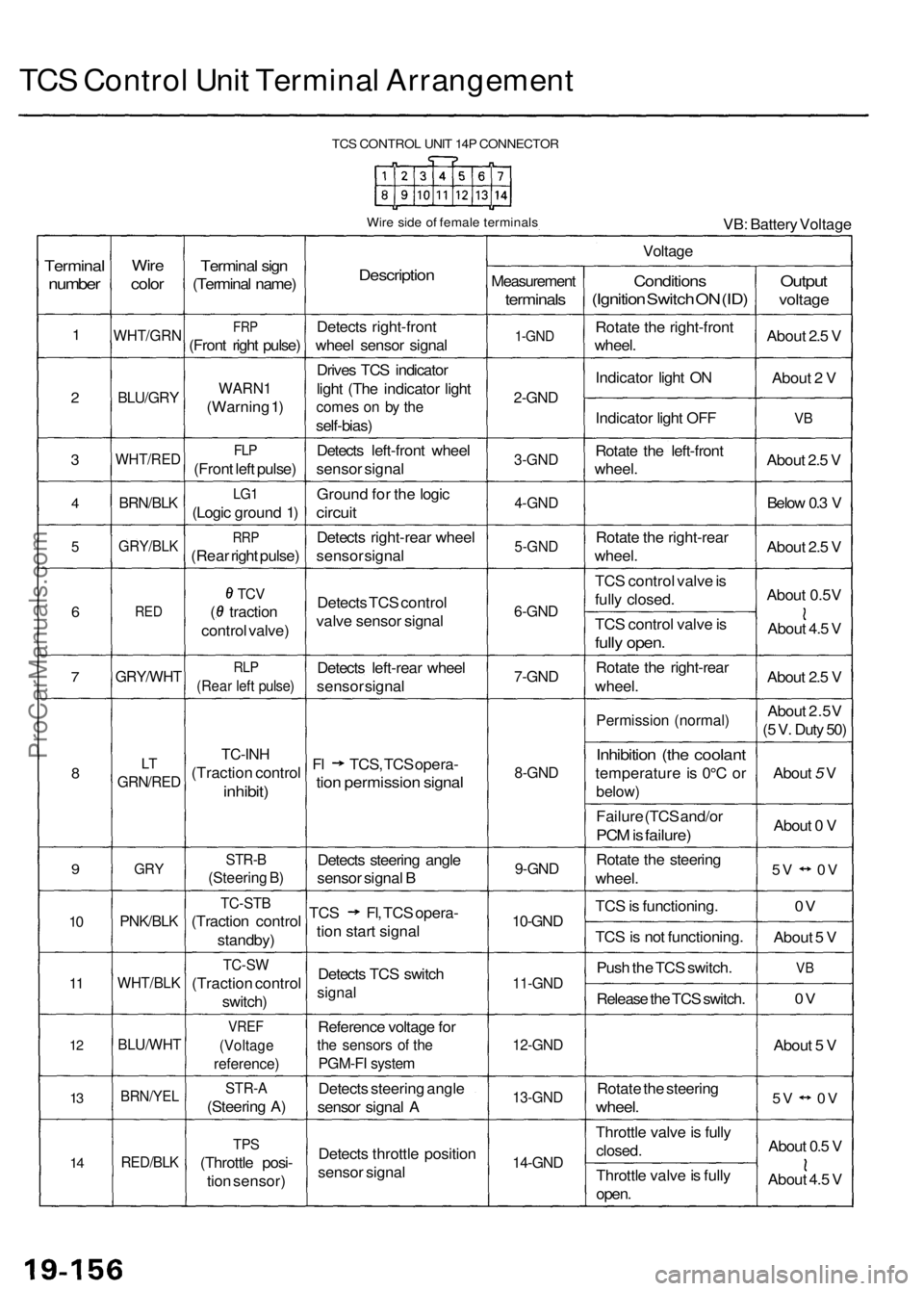
TCS Control Unit Terminal Arrangement
TCS CONTROL UNIT 14P CONNECTOR
Wire side of female terminals
VB: Battery Voltage
Terminal
number
1
2
3
4
5
6
7
8
9
10
11
12
13
14
Wire
color
WHT/GRN
BLU/GRY
WHT/RED
BRN/BLK
GRY/BLK
RED
GRY/WHT
LT
GRN/RED
GRY
PNK/BLK
WHT/BLK
BLU/WHT
BRN/YEL
RED/BLK
Terminal sign
(Terminal name)
FRP
(Front right pulse)
WARN1
(Warning 1)
FLP
(Front left pulse)
LG1
(Logic ground 1)
RRP
(Rear right pulse)
TCV
( traction
control valve)
RLP
(Rear left pulse)
TC-INH
(Traction control
inhibit)
STR-B
(Steering B)
TC-STB
(Traction control
standby)
TC-SW
(Traction control
switch)
VREF
(Voltage
reference)
STR-A
(Steering A)
TPS
(Throttle posi-
tion sensor)
Description
Detects right-front
wheel sensor signal
Drives TCS indicator
light (The indicator light
comes on by the
self-bias)
Detects left-front wheel
sensor signal
Ground for the logic
circuit
Detects right-rear wheel
sensor signal
Detects TCS control
valve sensor signal
Detects left-rear wheel
sensor signal
Fl TCS, TCS opera-
tion permission signal
Detects steering angle
sensor signal B
TCS Fl, TCS opera-
tion start signal
Detects TCS switch
signal
Reference voltage for
the sensors of the
PGM-FI system
Detects steering angle
sensor signal A
Detects throttle position
sensor signal
Voltage
Measurement
terminals
1-GND
2-GND
3-GND
4-GND
5-GND
6-GND
7-GND
8-GND
9-GND
10-GND
11-GND
12-GND
13-GND
14-GND
Conditions
(Ignition Switch ON (ID)
Rotate the right-front
wheel.
Indicator light ON
Indicator light OFF
Rotate the left-front
wheel.
Rotate the right-rear
wheel.
TCS control valve is
fully closed.
TCS control valve is
fully open.
Rotate the right-rear
wheel.
Permission (normal)
Inhibition (the coolant
temperature is 0°C or
below)
Failure (TCS and/or
PCM is failure)
Rotate the steering
wheel.
TCS is functioning.
TCS is not functioning.
Push the TCS switch.
Release the TCS switch.
Rotate the steering
wheel.
Throttle valve is fully
closed.
Throttle valve is fully
open.
Output
voltage
About 2.5 V
About 2 V
VB
About 2.5 V
Below 0.3 V
About 2.5 V
About 0.5V
About 4.5 V
About 2.5 V
About 2.5V
(5 V. Duty 50)
About 5 V
About 0 V
5V 0V
0V
About 5 V
VB
0V
About 5 V
5V 0V
About 0.5 V
About 4.5 VProCarManuals.com
Page 1196 of 1954
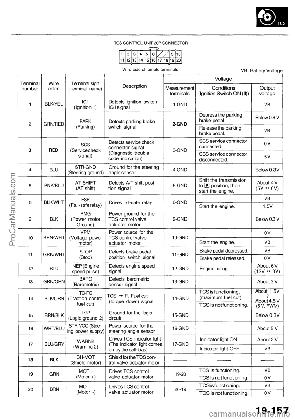
TCS CONTROL UNIT 20P CONNECTOR
Wire side of female terminals
VB: Battery Voltage
Terminal
number
1
2
4
5
6
9
10
11
12
13
14
15
16
17
20
Wire
color
BLK/YEL
GRN/RED
BLU
PNK/BLU
BLK/WHT
BLK
BRN/WHT
GRN/WHT
BLU
GRN/ORN
BLK/ORN
BRN/BLK
WHT/BLU
BLU/GRY
GRN
BRN
Terminal sign
(Terminal name)
IG1
(Ignition 1)
PARK
(Parking)
SCS
(Service check
signal)
STR-GND
(Steering ground)
AT-SHIFT
(AT shift)
FSR
(Fail-safe relay)
PMG
(Power motor
Ground)
VPM
(Voltage power
motor)
STOP
(Stop)
NEP (Engine
speed pulse)
BARO
(Barometric)
TC-FC
(Traction control
fuel cut)
LG2
(Logic ground 2)
STR-VCC (Steer-
ing power supply)
WARN2
(Warning 2)
SH-MOT
(Shield motor)
MOT +
(Motor +)
MOT-
(Motor -)
Description
Detects ignition switch
IG1 signal
Detects parking brake
switch signal
Detects service check
connector signal
(Diagnostic trouble
code indication)
Ground for the steering
angle sensor
Detects A/T shift posi-
tion signal
Drives fail-safe relay
Power ground for the
TCS control valve
actuator motor
Power source for the
TCS control valve
actuator motor
Detects brake pedal
position switch signal
Detects engine speed
signal
Detects barometric
sensor signal
TCS Fl, Fuel cut
(torque down) signal
Ground for the logic
circuit
Power source for the
steering angle sensor
Drives TCS indicator light
(The indicator light comes
on by the self-bias)
Shield for the TCS con-
trol valve actuator motor
Drives TCS control
valve actuator motor
Drives TCS control
valve actuator motor
Measurement
terminals
1-GND
2
3-GND
4-GND
5-GND
6-GND
9-GND
10-GND
11-GND
12-GND
13-GND
14-GND
15-GND
16-GND
17-GND
19-20
20-19
Voltage
Conditions
(Ignition Switch ON (II))
Depress the parking
brake pedal.
Release the parking
brake pedal.
SCS service connector
connected.
SCS service connector
disconnected.
Shift the transmission
to position, then
start the engine.
Start the engine.
Start the engine.
Brake pedal depressed.
Brake pedal released.
Engine idling
TCS is functioning,
(maximum fuel cut)
TCS is not functioning.
Indicator light ON
Indicator light OFF
TCS is functioning.
TCS is not functioning.
TCS is functioning.
TCS is not functioning.
Output
voltage
VB
Below 0.6 V
VB
0V
5V
Below 0.3V
About 4V
(5V 0V)
VB
1.5V
Below 0.3 V
0V
VB
VB
0V
About 6V
(12V
0V)
About 3 V
About 1.5V
About 4.5 V
(5 V,
PWM)
Below 0.3V
About 5 V
About 2 V
VB
VB
0V
VB
0VProCarManuals.com
Page 1199 of 1954
Diagnostic Trouble Code (DTC)
DTC Erasure
1. Press the parking brake pedal.
2. Push and hold the TCS switch, then turn the ignition switch ON (II).
3. Hold the TCS switch pushed for 4 to 6 seconds, then release the TCS switch.
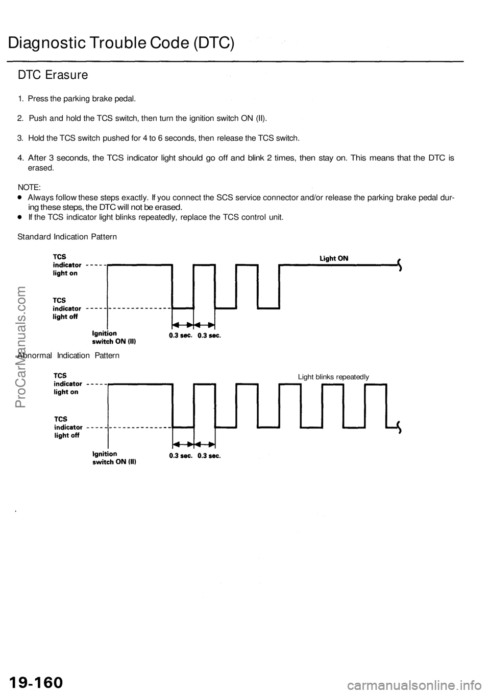
4. After 3 seconds, the TCS indicator light should go off and blink 2 times, then stay on. This means that the DTC is
erased.
NOTE:
Always follow these steps exactly. If you connect the SCS service connector and/or release the parking brake pedal dur-
ing these steps, the DTC will not be erased.
If the TCS indicator light blinks repeatedly, replace the TCS control unit.
Standard Indication Pattern
Abnormal Indication Pattern
Light blinks repeatedlyProCarManuals.com
Page 1214 of 1954
![ACURA RL KA9 1996 Service Repair Manual
PGM-FI DTC: 36 [TC-FC signal (High-Low check)]
Check for a short to body ground
in the TC-FC circuit:
1. Disconnect the PCM connec-
tor C (12P) and TCS control
unit 20P connectors.
2. Check for ACURA RL KA9 1996 Service Repair Manual
PGM-FI DTC: 36 [TC-FC signal (High-Low check)]
Check for a short to body ground
in the TC-FC circuit:
1. Disconnect the PCM connec-
tor C (12P) and TCS control
unit 20P connectors.
2. Check for](/manual-img/32/56992/w960_56992-1213.png)
PGM-FI DTC: 36 [TC-FC signal (High-Low check)]
Check for a short to body ground
in the TC-FC circuit:
1. Disconnect the PCM connec-
tor C (12P) and TCS control
unit 20P connectors.
2. Check for continuity between
the TCS control unit 20P con-
nector terminal No. 14 and
body ground.
TCS CONTROL UNIT 20P CONNECTOR
Is there continuity?
Repair short to body ground in
the wire between the PCM and
TCS control unit.
Wire side of female terminals
TCS IS NOT TCS IS
FUNCTIONING FUNCTIONING
NOTE: Use the 10 V range or a similar
range in an analog tester.
Is there about 4.5 V when TCS is
not functioning?
Check for loose TCS control unit
connector. If necessary, substi-
tute a known-good TCS control
unit and recheck.
Check for an open in the TC-FC
circuit:
Measure the voltage between the
PCM connector C (12P) terminal
No. 10 and body ground.
NOTE: Use the 10 V range or a similar
range in an analog tester.
TCS IS NOT TCS IS
FUNCTIONING FUNCTIONING
PCM CONNECTOR C (12P)
Is there about 4.5 V when TCS is
not functioning?
Repair open in the wire between
the TCS control unit and PCM.
Wire side of female terminals
Check for loose PCM connectors.
If necessary, substitute a known-
good PCM and recheck.
Check the TCS control unit:
1. Connect the TCS control unit
20P connector.
2. Turn the ignition switch ON
(II).
3. Measure the voltage between
the TCS control unit 20P con-
nector terminal No. 14 and
body ground.ProCarManuals.com
Page 1225 of 1954
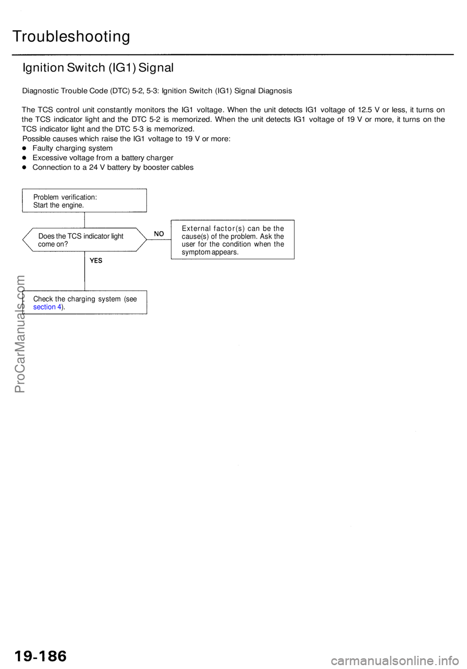
Troubleshooting
Ignition Switc h (IG1 ) Signa l
Diagnosti c Troubl e Cod e (DTC ) 5-2 , 5-3 : Ignitio n Switc h (IG1 ) Signa l Diagnosi s
Th e TC S contro l uni t constantl y monitor s th e IG 1 voltage . Whe n th e uni t detect s IG 1 voltag e o f 12. 5 V or less , i t turn s o n
th e TC S indicato r ligh t an d th e DT C 5- 2 i s memorized . Whe n th e uni t detect s IG 1 voltag e o f 1 9 V or more , i t turn s o n th e
TC S indicato r ligh t an d th e DT C 5- 3 is memorized .
Possibl e cause s whic h rais e th e IG 1 voltag e to 1 9 V or more :
Fault y chargin g syste m
Excessiv e voltag e fro m a batter y charge r
Connectio n t o a 24 V batter y b y booste r cable s
Proble m verification :
Star t th e engine .
Does th e TC S indicato r ligh tcom e on ? Externa
l factor(s ) ca n b e th e
cause(s ) o f th e problem . As k th e
use r fo r th e conditio n whe n th e
sympto m appears .
Chec k th e chargin g syste m (se e
sectio n 4 ).
ProCarManuals.com
Page 1236 of 1954
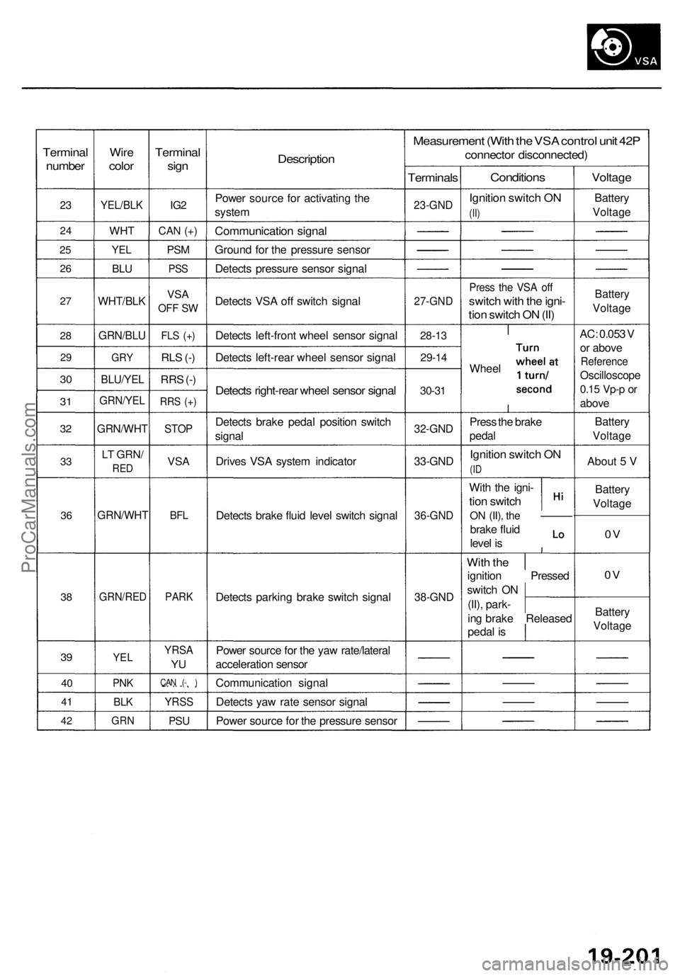
Terminal
number
23
2 4
25
2 6
27
2 8
2 9
30
3 1
3 2
33
3 6
38
39
4 0
4 1
42
Wir e
colo r
YEL/BL K
WHT
YEL
BLU
WHT/BL K
GRN/BLU
GRY
BLU/YE L
GRN/YE L
GRN/WH T
LT GRN /
RED
GRN/WH T
GRN/RED
YEL
PNK
BLK
GR N
Termina l
sign
IG2
CA N (+ )
PS M
PS S
VS A
OF F S W
FL S (+ )
RLS (- )
RR S (- )
RR S (+ )
STO P
VSA
BFL
PAR K
YRS A
YU
CA N ( - )
YRS S
PSU
Descriptio n
Power sourc e fo r activatin g th e
syste m
Communicatio n signa l
Groun d fo r th e pressur e senso r
Detect s pressur e senso r signa l
Detect s VS A of f switc h signa l
Detect s left-fron t whee l senso r signa l
Detect s left-rea r whee l senso r signa l
Detects right-rea r whee l senso r signa l
Detect s brak e peda l positio n switc h
signa l
Drive s VS A syste m indicato r
Detect s brak e flui d leve l switc h signa l
Detect s parkin g brak e switc h signa l
Powe r sourc e fo r th e ya w rate/latera l
acceleratio n senso r
Communicatio n signa l
Detect s ya w rat e senso r signa l
Powe r sourc e fo r th e pressur e senso r
Measuremen t (Wit h th e VS A contro l uni t 42 P
connecto r disconnected )
Terminals
23-GND
27-GN D
28-13
29-1 4
30-31
32-GN D
33-GND
36-GN D
38-GND
Condition s
Ignition switc h O N
(II)
Pres s th e VS A of f
switc h wit h th e igni -
tion switc h O N (II )
Whee l
Pres s th e brak e
peda l
Ignitio n switc h O N
(ID
Wit h th e igni -
tion switc h
ON (II) , the —— —
brake flui d
leve l i s
Wit h th e
ignitio n Presse d
switc h O N
(II) , park -
in g brak e Release d
peda l i s
Voltag e
Battery
Voltag e
Battery
Voltag e
AC: 0.05 3 V
o r abov e
Referenc e
Oscilloscop e
0.15 Vp- p or
abov e
Batter y
Voltag e
About 5 V
Batter y
Voltag e
0V
0 V
Batter y
Voltag e
ProCarManuals.com
Page 1245 of 1954
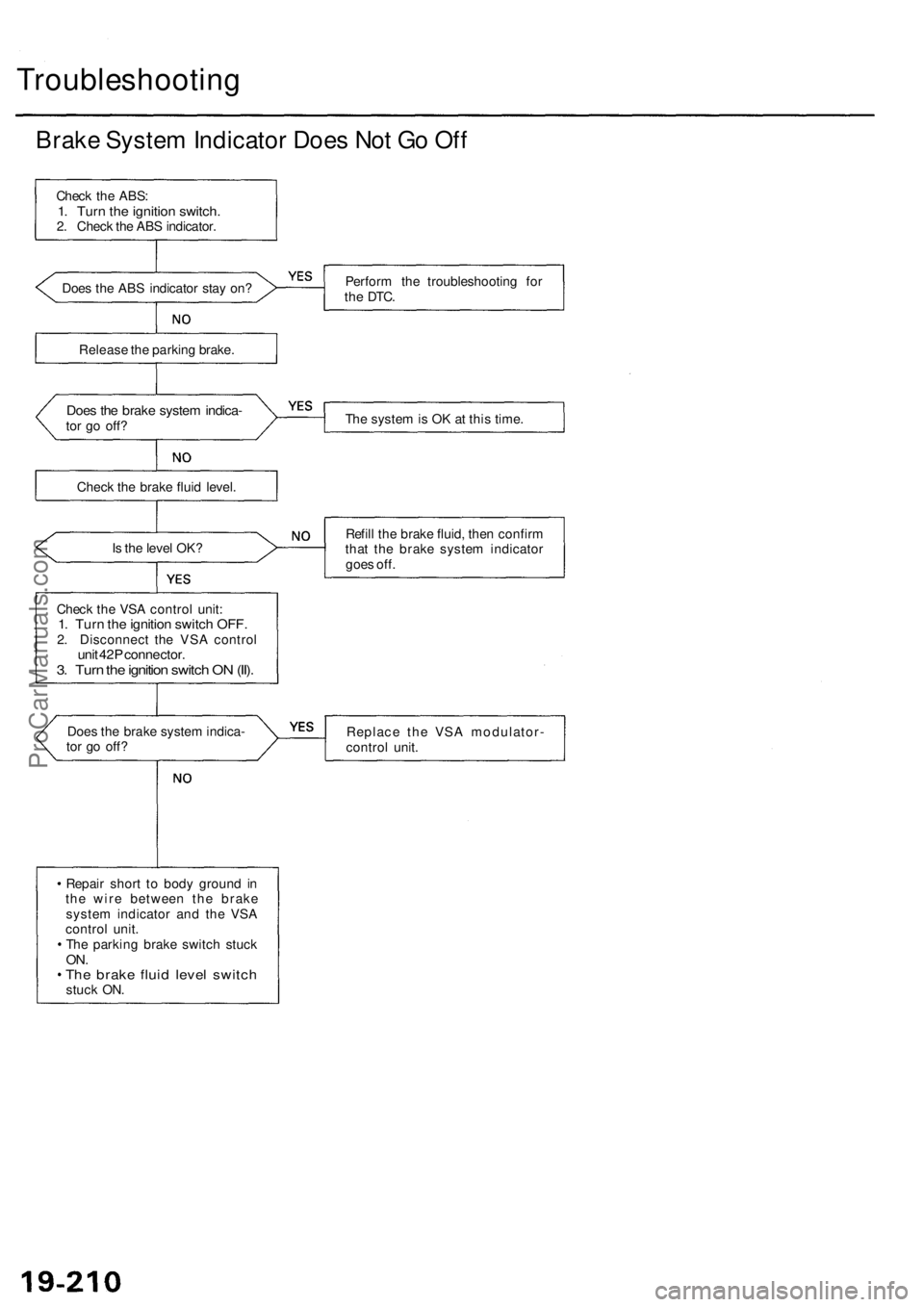
Troubleshooting
Brake System Indicator Does Not Go Off
Check the ABS:
1. Turn the ignition switch.
2. Check the ABS indicator.
Does the ABS indicator stay on?
Perform the troubleshooting for
the
DTC.
Release the parking brake.
Does the brake system indica-
tor go off?
The system is OK at this time.
Check the brake fluid level.
Is the level OK?
Refill the brake fluid, then confirm
that the brake system indicator
goes off.
Check the VSA control unit:
1. Turn the ignition switch OFF.
2. Disconnect the VSA control
unit 42P connector.
3. Turn the ignition switch ON (II).
Does the brake system indica-
tor go off?
Replace the VSA modulator-
control unit.
Repair short to body ground in
the wire between the brake
system indicator and the VSA
control unit.
The parking brake switch stuck
ON.
The brake fluid level switch
stuck ON.ProCarManuals.com