1996 ACURA RL KA9 ignition
[x] Cancel search: ignitionPage 1608 of 1954
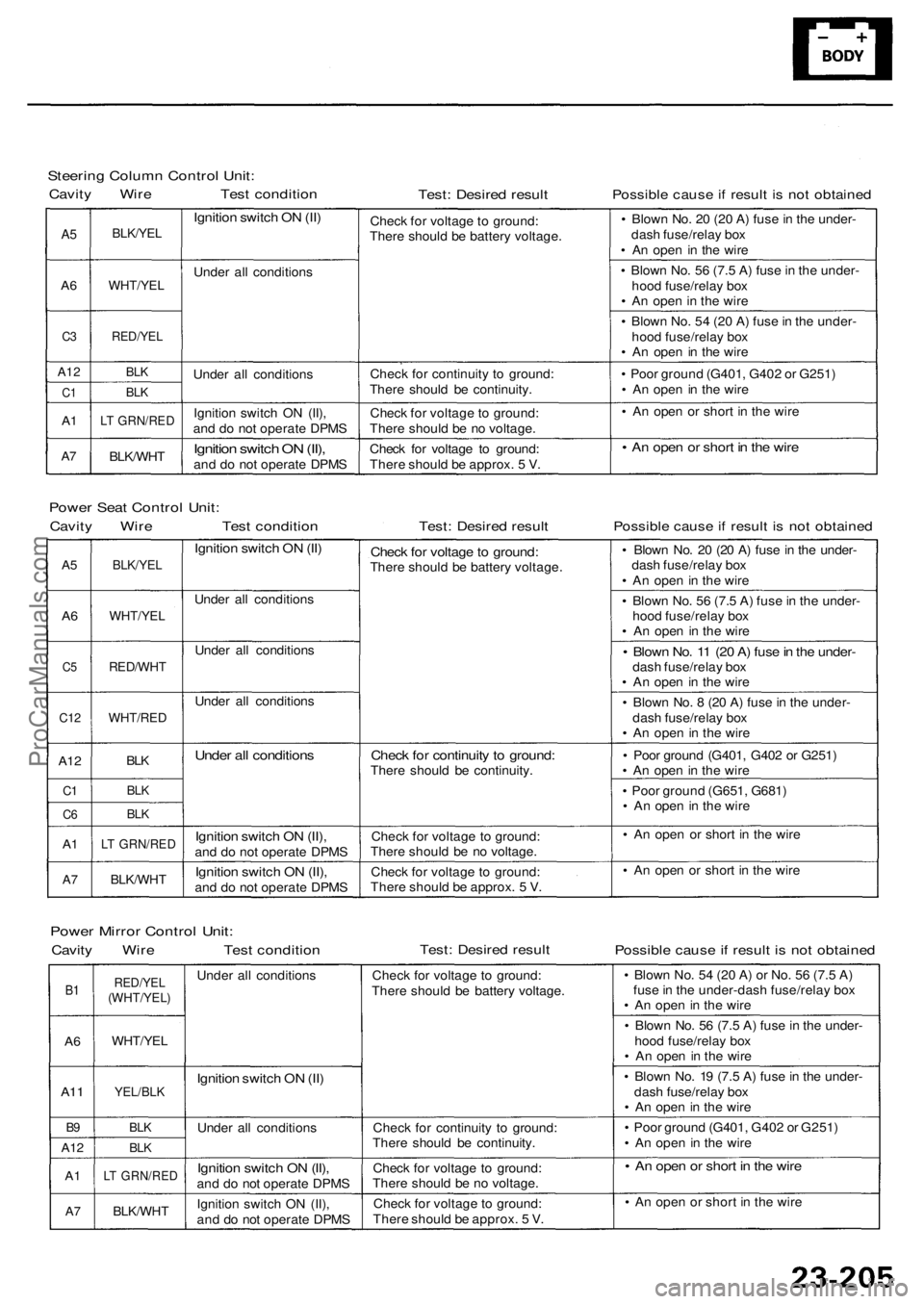
Steering Colum n Contro l Unit :
Cavit y Wir e Tes t conditio nTest: Desire d resul tPossibl e caus e if resul t i s no t obtaine d
A5
A 6
C 3
A1 2
C1
A1
A7
BLK/YE L
WHT/YE L
RED/YEL
BLK
BL K
LT GRN/RE D
BLK/WHT
Ignition switc h O N (II )
Unde r al l condition s
Unde r al l condition s
Ignitio n switc h O N (II) ,
an d d o no t operat e DPM S
Ignition switc h O N (II) ,and d o no t operat e DPM SChec
k fo r voltag e t o ground :
Ther e shoul d b e batter y voltage .
Chec k fo r continuit y t o ground :
Ther e shoul d b e continuity .
Chec k fo r voltag e to ground :
Ther e shoul d b e n o voltage .
Chec k fo r voltag e t o ground :
Ther e shoul d b e approx . 5 V . •
Blow n No . 2 0 (2 0 A ) fus e in th e under -
das h fuse/rela y bo x
• A n ope n i n th e wire
• Blow n No . 5 6 (7. 5 A ) fus e in th e under -
hoo d fuse/rela y bo x
• A n ope n in th e wir e
• Blow n No . 5 4 (2 0 A ) fus e in th e under -
hoo d fuse/rela y bo x
• A n ope n i n th e wir e
• Poo r groun d (G401 , G40 2 o r G251 )
• A n ope n in th e wir e
• A n ope n o r shor t i n th e wir e
• A n ope n o r shor t i n th e wir e
Powe r Sea t Contro l Unit :
Cavit y Wir e Tes t conditio nTest: Desire d resul tPossibl e caus e if resul t i s no t obtaine d
A5
A6
C 5
C1 2
A12
C1
C 6
A1
A 7
BLK/YE L
WHT/YE L
RED/WH T
WHT/RED
BLK
BL K
BL K
LT GRN/RE D
BLK/WHT
Ignition switc h O N (II )
Unde r al l condition s
Unde r al l condition s
Unde r al l condition s
Under al l condition s
Ignition switc h O N (II) ,and d o no t operat e DPM S
Ignitio n switc h O N (II) ,and d o no t operat e DPM S
Check fo r voltag e to ground :There shoul d b e batter y voltage .
Check fo r continuit y t o ground :There shoul d b e continuity .
Chec k fo r voltag e t o ground :
Ther e shoul d b e n o voltage .
Chec k fo r voltag e t o ground :
Ther e shoul d b e approx . 5 V . •
Blow n No . 2 0 (2 0 A ) fus e in th e under -
das h fuse/rela y bo x
• A n ope n in th e wir e
• Blow n No . 5 6 (7. 5 A ) fus e in th e under -
hoo d fuse/rela y bo x
• A n ope n i n th e wire
• Blow n No . 1 1 (2 0 A ) fus e in th e under -dash fuse/rela y bo x
• A n ope n i n th e wir e
• Blow n No . 8 (2 0 A ) fus e in th e under -
das h fuse/rela y bo x
• A n ope n in th e wir e
• Poo r groun d (G401 , G40 2 o r G251 )
• A n ope n in th e wir e
• Poo r groun d (G651 , G681 )
• A n ope n in th e wir e
• A n ope n o r shor t i n th e wir e
• A n ope n o r shor t i n th e wir e
Powe r Mirro r Contro l Unit :
Cavit y Wir e Tes t conditio nTest: Desire d resul tPossibl e caus e if resul t i s no t obtaine d
B1
A 6
A1 1
B9
A1 2
A1
A7
RED/YE L(WHT/YEL )
WHT/YEL
YEL/BLK
BLK
BLK
LT GRN/RE D
BLK/WHT
Under al l condition s
Ignition switc h O N (II )
Unde r al l condition s
Ignition switc h O N (II) ,and d o no t operat e DPM S
Ignitio n switc h O N (II) ,
an d d o no t operat e DPM SChec
k fo r voltag e t o ground :
Ther e shoul d b e batter y voltage .
Chec k fo r continuit y t o ground :
Ther e shoul d b e continuity .
Chec k fo r voltag e t o ground :
Ther e shoul d b e n o voltage .
Chec k fo r voltag e t o ground :
Ther e shoul d b e approx . 5 V . •
Blow n No . 5 4 (2 0 A ) o r No . 5 6 (7. 5 A )
fus e in th e under-das h fuse/rela y bo x
• A n ope n in th e wir e
• Blow n No . 5 6 (7. 5 A ) fus e in th e under -
hoo d fuse/rela y bo x
• A n ope n in th e wire
• Blow n No . 1 9 (7. 5 A ) fus e in th e under -
das h fuse/rela y bo x
• A n ope n in th e wir e
• Poo r groun d (G401 , G40 2 o r G251 )
• A n ope n i n th e wir e
• A n ope n o r shor t i n th e wir e
• A n ope n o r shor t i n th e wir e
ProCarManuals.com
Page 1634 of 1954
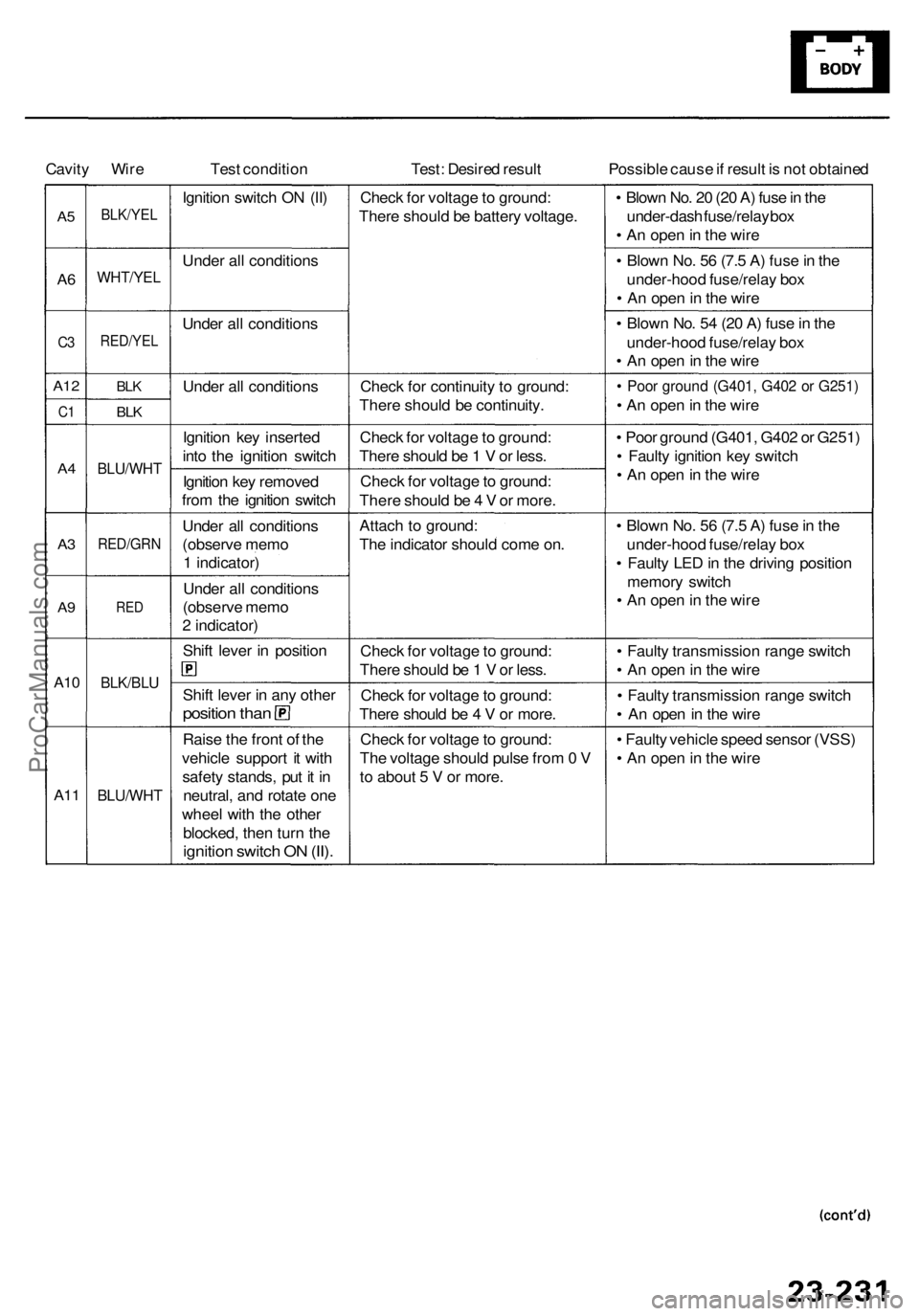
Cavity Wir e Test conditio n Test: Desire d resul t Possible caus e if resul t i s no t obtaine d
A5
A6
C 3
A1 2
C1
A4
A3
A 9
A1 0
A1 1
BLK/YE L
WHT/YE L
RED/YEL
BLK
BLK
BLU/WH T
RED/GR N
RED
BLK/BL U
BLU/WH T
Ignition switc h O N (II )
Unde r al l condition s
Unde r al l condition s
Unde r al l condition s
Ignitio n ke y inserte d
int o th e ignitio n switc h
Ignitio n ke y remove d
fro m th e ignitio n switc h
Unde r al l condition s
(observ e mem o
1 indicator )
Unde r al l condition s
(observ e mem o
2 indicator )
Shif t leve r i n positio n
Shift leve r i n an y othe r
positio n tha n
Rais e th e fron t o f th e
vehicl e suppor t i t wit h
safet y stands , pu t i t i n
neutral , an d rotat e on e
whee l wit h th e othe r
blocked , the n tur n th e
ignitio n switc h O N (II) .
Chec k fo r voltag e to ground :
Ther e shoul d b e batter y voltage .
Chec k fo r continuit y t o ground :
Ther e shoul d b e continuity .
Chec k fo r voltag e to ground :
Ther e shoul d b e 1 V or less .
Chec k fo r voltag e to ground :
Ther e shoul d b e 4 V or more .
Attac h t o ground :
Th e indicato r shoul d com e on .
Chec k fo r voltag e to ground :
Ther e shoul d b e 1 V or less .
Chec k fo r voltag e to ground :
Ther e shoul d b e 4 V or more .
Chec k fo r voltag e to ground :
Th e voltag e shoul d puls e fro m 0 V
t o abou t 5 V or more . •
Blow n No . 2 0 (2 0 A ) fus e in th e
under-das h fuse/rela y bo x
• A n ope n in th e wir e
• Blow n No . 5 6 (7. 5 A ) fus e in th e
under-hoo d fuse/rela y bo x
• A n ope n in th e wir e
• Blow n No . 5 4 (2 0 A ) fus e in th e
under-hoo d fuse/rela y bo x
• A n ope n in th e wir e
• Poo r groun d (G401 , G40 2 o r G251 )
• A n ope n in th e wir e
• Poo r groun d (G401 , G40 2 o r G251 )
• Fault y ignitio n ke y switc h
• A n ope n in th e wir e
• Blow n No . 5 6 (7. 5 A ) fus e in th e
under-hoo d fuse/rela y bo x
• Fault y LE D in th e drivin g positio n
memor y switc h
• A n ope n in th e wir e
• Fault y transmissio n rang e switc h
• A n ope n in th e wir e
• Fault y transmissio n rang e switc h
• A n ope n in th e wir e
• Fault y vehicl e spee d senso r (VSS )
• A n ope n in th e wir e
ProCarManuals.com
Page 1638 of 1954
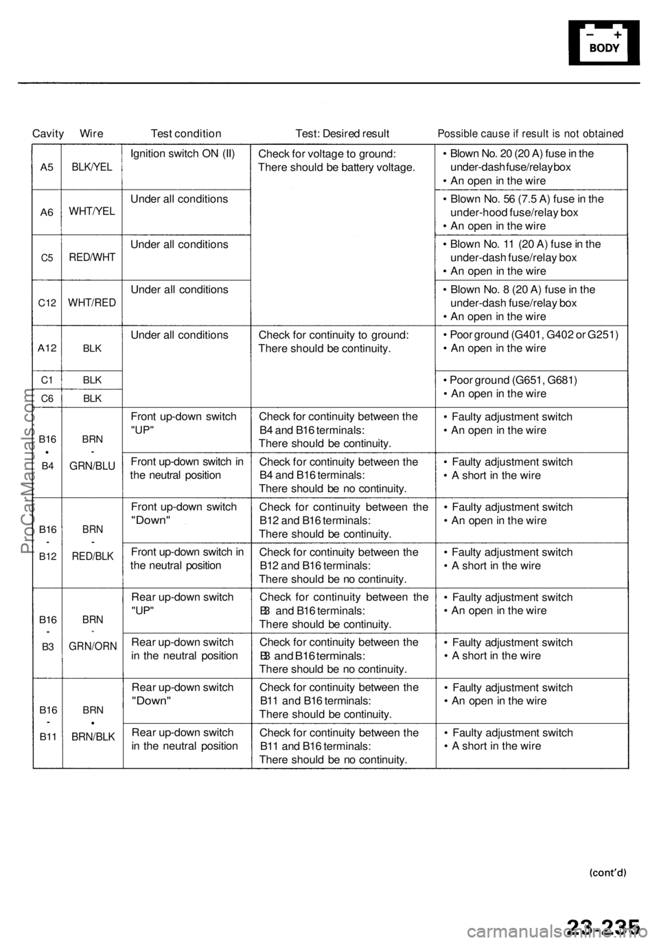
Cavity Wir e Test conditio n Test: Desire d resul tPossibl e caus e if resul t i s no t obtaine d
A5
A 6
C 5
C1 2
A12
C1
C 6
B1 6
B4
B1 6•
B1 2
B16•
B3
B1 6•
B11
BLK/YE L
WHT/YE L
RED/WH T
WHT/RED
BLK
BLK
BLK
BR N•
GRN/BL U
BRN•
RED/BL K
BRN*
GRN/OR N
BRN
BRN/BL K
Ignition switc h O N (II )
Unde r al l condition s
Unde r al l condition s
Unde r al l condition s
Unde r al l condition s
Fron t up-dow n switc h
"UP"
Fron t up-dow n switc h in
th e neutra l positio n
Fron t up-dow n switc h
"Down "
Front up-dow n switc h in
th e neutra l positio n
Rea r up-dow n switc h
"UP"
Rea r up-dow n switc h
i n th e neutra l positio n
Rea r up-dow n switc h
"Down "
Rear up-dow n switc h
i n th e neutra l positio nChec
k fo r voltag e to ground :
Ther e shoul d b e batter y voltage .
Chec k fo r continuit y t o ground :
Ther e shoul d b e continuity .
Chec k fo r continuit y betwee n th e
B 4 an d B1 6 terminals :
Ther e shoul d b e continuity .
Chec k fo r continuit y betwee n th e
B 4 an d B1 6 terminals :
Ther e shoul d b e n o continuity .
Chec k fo r continuit y betwee n th e
B1 2 an d B1 6 terminals :
Ther e shoul d b e continuity .
Chec k fo r continuit y betwee n th e
B1 2 an d B1 6 terminals :
Ther e shoul d b e n o continuity .
Chec k fo r continuit y betwee n th e
B 3 an d B1 6 terminals :
Ther e shoul d b e continuity .
Chec k fo r continuit y betwee n th e
B3 an d B1 6 terminals :
There shoul d b e n o continuity .
Chec k fo r continuit y betwee n th e
B1 1 an d B1 6 terminals :
Ther e shoul d b e continuity .
Chec k fo r continuit y betwee n th e
B1 1 an d B1 6 terminals :
Ther e shoul d b e n o continuity .•
Blow n No . 2 0 (2 0 A ) fus e in th e
under-das h fuse/rela y bo x
• A n ope n in th e wir e
• Blow n No . 5 6 (7. 5 A ) fus e in th e
under-hoo d fuse/rela y bo x
• A n ope n in th e wir e
• Blow n No . 1 1 (2 0 A ) fus e in th e
under-das h fuse/rela y bo x
• A n ope n in th e wir e
• Blow n No . 8 (2 0 A ) fus e in th e
under-das h fuse/rela y bo x
• A n ope n in th e wir e
• Poo r groun d (G401 , G40 2 o r G251 )
• A n ope n in th e wir e
• Poo r groun d (G651 , G681 )
• A n ope n in th e wir e
• Fault y adjustmen t switc h
• A n ope n in th e wir e
• Fault y adjustmen t switc h
• A shor t i n th e wir e
• Fault y adjustmen t switc h
• A n ope n in th e wir e
• Fault y adjustmen t switc h
• A shor t i n th e wir e
• Fault y adjustmen t switc h
• A n ope n in th e wir e
• Fault y adjustmen t switc h
• A shor t i n th e wir e
• Fault y adjustmen t switc h
• A n ope n in th e wir e
• Fault y adjustmen t switc h
• A shor t i n th e wir e
ProCarManuals.com
Page 1642 of 1954
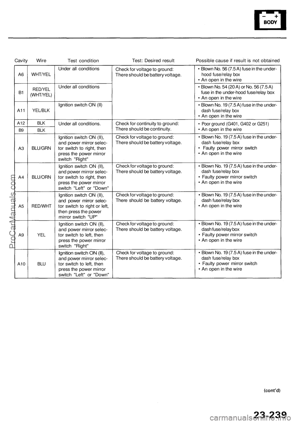
Cavity Wir e
Test conditio n Test
: Desire d resul t Possible caus e if resul t i s no t obtaine d
A6
B1
A1 1
A1 2
B9
A 3
A 4
A5
A9
A1 0
WHT/YE L
RED/YEL
(WHT/YEL )
YEL/BLK
BLK
BL K
BLU/GR N
BLU/OR N
RED/WH T
YEL
BLU
Unde r al l condition s
Unde r al l condition s
Ignitio n switc h O N (II )
Unde r al l conditions .
Ignitio n switc h O N (II) ,
an d powe r mirro r selec -
to r switc h t o right , the n
pres s th e powe r mirro r
switc h "Right "
Ignitio n switc h O N (II) ,
an d powe r mirro r selec -
to r switc h t o right , the n
pres s th e powe r mirro r
switc h "Left " o r "Down "
Ignitio n switc h O N (II) ,
an d powe r mirro r selec -
to r switc h t o righ t o r left ,
the n pres s th e powe r
mirro r switc h "UP "
Ignitio n switc h O N (II) ,
an d powe r mirro r selec -
to r switc h t o left , the n
pres s th e powe r mirro r
switc h "Right "
Ignition switc h O N (II) ,
and powe r mirro r selec -
to r switc h t o left , the n
pres s th e powe r mirro r
switc h "Left " o r "Down "Chec
k fo r voltag e to ground :
Ther e shoul d b e batter y voltage .
Chec k fo r continuit y to ground :
Ther e shoul d b e continuity .
Chec k fo r voltag e to ground :
Ther e shoul d b e batter y voltage .
Chec k fo r voltag e to ground :
Ther e shoul d b e batter y voltage .
Chec k fo r voltag e to ground :
Ther e shoul d b e batter y voltage .
Chec k fo r voltag e to ground :
Ther e shoul d b e batter y voltage .
Chec k fo r voltag e to ground :
Ther e shoul d b e batter y voltage . •
Blow n No . 5 6 (7. 5 A ) fus e in th e under -
hood fuse/rela y bo x• A n ope n in th e wir e
• Blow n No . 5 4 (2 0 A ) o r No . 5 6 (7. 5 A )
fus e in th e under-hoo d fuse/rela y bo x
• A n ope n in th e wir e
• Blow n No . 1 9 (7. 5 A ) fus e in th e under -
dash fuse/rela y bo x• A n ope n in th e wir e
• Poo r groun d (G401 , G40 2 o r G251 )
• A n ope n in th e wir e
• Blow n No . 1 9 (7. 5 A ) fus e in th e under -
dash fuse/rela y bo x• Fault y powe r mirro r switc h
• A n ope n in th e wir e
• Blow n No . 1 9 (7. 5 A ) fus e in th e under -
dash fuse/rela y bo x
• Fault y powe r mirro r switc h
• A n ope n in th e wir e
• Blow n No . 1 9 (7. 5 A ) fus e in th e under -
das h fuse/rela y bo x
• A n ope n in th e wir e
• Blow n No . 1 9 (7. 5 A ) fus e in th e under -
das h fuse/rela y bo x
• Fault y powe r mirro r switc h
• A n ope n in th e wir e
• Blow n No . 1 9 (7. 5 A ) fus e in th e under -
dash fuse/rela y bo x• Fault y powe r mirro r switc h
• A n ope n in th e wir e
ProCarManuals.com
Page 1643 of 1954
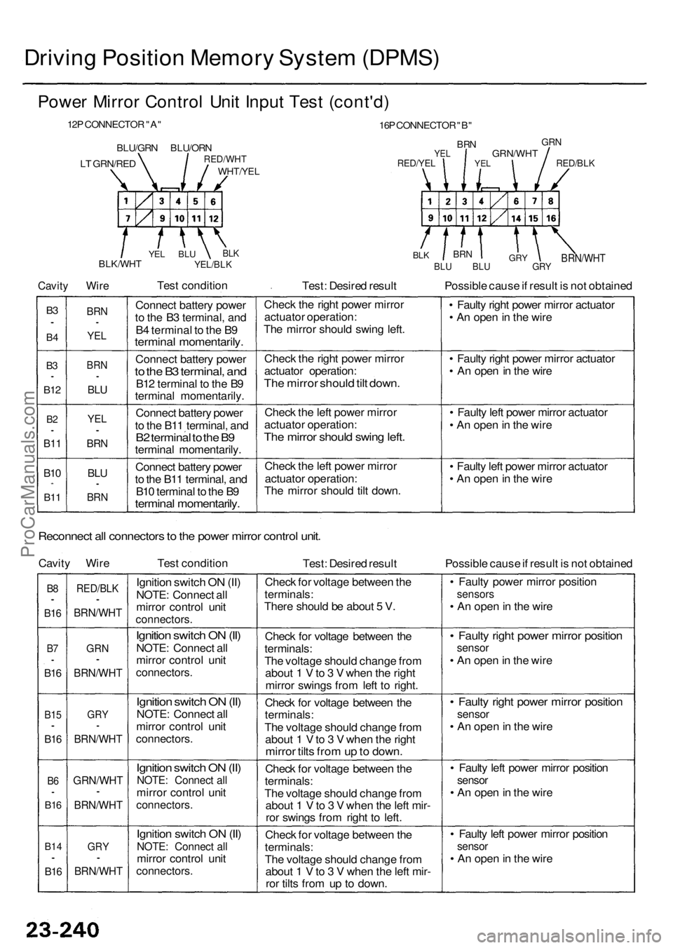
Driving Positio n Memor y Syste m (DPMS )
Power Mirro r Contro l Uni t Inpu t Tes t (cont'd )
12P CONNECTO R "A "
BLU/GR N BLU/OR NRED/WHT
WHT/YEL
16P CONNECTO R "B "
BR NYELGR N
RED/YE LGRN/WH TRED/BLK
Cavity
BLK/WH T
Wire
BLKYEL/BL K
Test conditio n
Test: Desire d resul t
BRN/WH TBLU BL U GR Y
Possible caus e if resul t i s no t obtaine d
B3•
B 4
B3•
B1 2
B2•
B1 1
B10*
B1 1
BR N•
YEL
BRN•
BLU
YE L•
BRN
BLU•
BR N
Connec t batter y powe r
t o th e B 3 terminal , an d
B 4 termina l t o th e B 9
termina l momentarily .
Connect batter y powe r
to th e B 3 terminal , an d
B12 termina l t o th e B 9
termina l momentarily .
Connec t batter y powe r
t o th e B1 1 terminal , an d
B2 termina l t o th e B 9termina l momentarily .
Connec t batter y powe r
t o th e B1 1 terminal , an d
B1 0 termina l t o th e B 9
termina l momentarily .
Check th e righ t powe r mirro r
actuato r operation :
Th e mirro r shoul d swin g left .
Chec k th e righ t powe r mirro r
actuato r operation :
The mirro r shoul d til t down .
Check th e lef t powe r mirro r
actuato r operation :
The mirro r shoul d swin g left .
Chec k th e lef t powe r mirro r
actuato r operation :
Th e mirro r shoul d til t down . •
Fault y righ t powe r mirro r actuato r
• A n ope n in th e wir e
• Fault y righ t powe r mirro r actuato r
• A n ope n in th e wir e
• Fault y lef t powe r mirro r actuato r
• A n ope n in th e wir e
• Fault y lef t powe r mirro r actuato r
• A n ope n in th e wir e
Reconnec t al l connector s to th e powe r mirro r contro l unit .
Cavit y Wir e Test conditio n
Test: Desire d resul t Possible caus e if resul t i s no t obtaine d
B8•
B1 6
B7•
B1 6
B1 5•
B16
B6•
B1 6
B1 4•
B16
RED/BL K•
BRN/WH T
GRN•
BRN/WH T
GRY•
BRN/WH T
GRN/WH T•
BRN/WHT
GRY•
BRN/WH T
Ignition switc h O N (II )
NOTE : Connec t al l
mirro r contro l uni t
connectors .
Ignition switc h O N (II )
NOTE : Connec t al l
mirro r contro l uni t
connectors .
Ignition switc h O N (II )
NOTE : Connec t al l
mirro r contro l uni t
connectors .
Ignition switc h O N (II )
NOTE : Connec t al l
mirro r contro l uni t
connectors .
Ignition switc h O N (II )
NOTE : Connec t al lmirro r contro l uni t
connectors .
Check fo r voltag e betwee n th e
terminals :
Ther e shoul d b e abou t 5 V .
Chec k fo r voltag e betwee n th e
terminals :
Th e voltag e shoul d chang e fro m
abou t 1 V to 3 V whe n th e righ t
mirro r swing s fro m lef t t o right .
Chec k fo r voltag e betwee n th e
terminals :
Th e voltag e shoul d chang e fro m
abou t 1 V to 3 V whe n th e righ t
mirro r tilt s fro m up to down .
Check fo r voltag e betwee n th e
terminals :
Th e voltag e shoul d chang e fro m
abou t 1 V to 3 V whe n th e lef t mir -
ro r swing s fro m righ t t o left .
Chec k fo r voltag e betwee n th e
terminals :
Th e voltag e shoul d chang e fro m
abou t 1 V to 3 V whe n th e lef t mir -
ro r tilt s fro m u p t o down . •
Fault y powe r mirro r positio n
sensors
• A n ope n in th e wir e
• Fault y righ t powe r mirro r positio nsensor
• A n ope n in th e wir e
• Fault y righ t powe r mirro r positio n
sensor
• A n ope n in th e wir e
• Fault y lef t powe r mirro r positio n
sensor
• A n ope n in th e wir e
• Fault y lef t powe r mirro r positio n
sensor
• A n ope n in th e wir e
YEL
GR YBRNBLKYE L BL U
LT GRN/RE D
ProCarManuals.com
Page 1647 of 1954
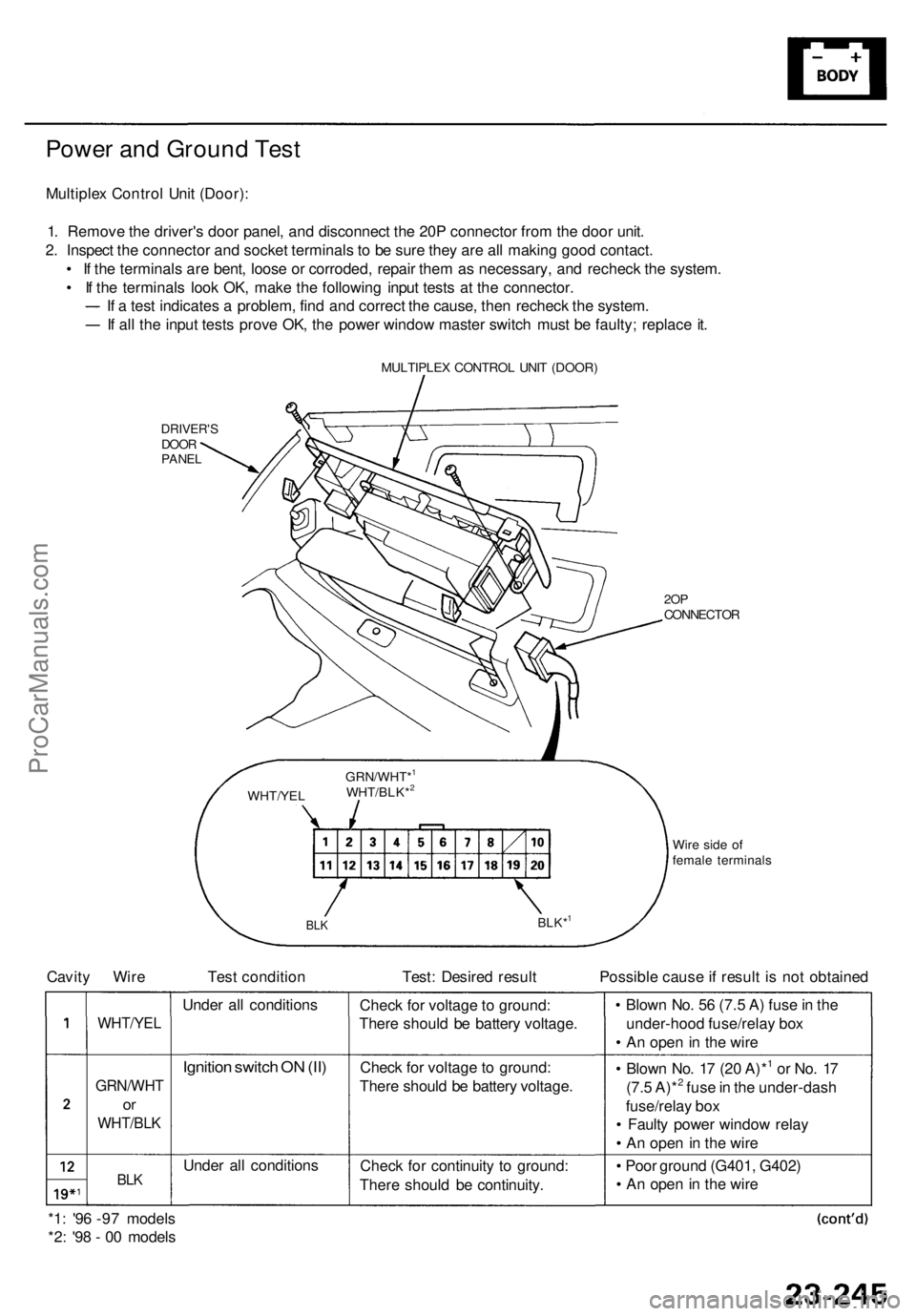
Power an d Groun d Tes t
Multiple x Contro l Uni t (Door) :
1 . Remov e th e driver' s doo r panel , an d disconnec t th e 20 P connecto r fro m th e doo r unit .
2 . Inspec t th e connecto r an d socke t terminal s t o b e sur e the y ar e al l makin g goo d contact .
• I f th e terminal s ar e bent , loos e o r corroded , repai r the m a s necessary , an d rechec k th e system .
• I f th e terminal s loo k OK , mak e th e followin g inpu t test s a t th e connector .
I f a tes t indicate s a problem , fin d an d correc t th e cause , the n rechec k th e system .
If al l th e inpu t test s prov e OK , th e powe r windo w maste r switc h mus t b e faulty ; replac e it .
MULTIPLE X CONTRO L UNI T (DOOR )
DRIVER' SDOORPANE L
2OPCONNECTO R
Wir e sid e o f
femal e terminal s
WHT/YE
LGRN/WHT*
1
WHT/BLK*2
BL
KBLK*1
Cavit y Wir e Tes t conditio n Test : Desire d resul t Possibl e caus e if resul t i s no t obtaine d
WHT/YE L
GRN/WH T
or
WHT/BL K
BLK
Unde r al l condition s
Ignition switc h O N (II )
Unde r al l condition sChec
k fo r voltag e to ground :
Ther e shoul d b e batter y voltage .
Chec k fo r voltag e to ground :
Ther e shoul d b e batter y voltage .
Chec k fo r continuit y t o ground :
Ther e shoul d b e continuity . •
Blow n No . 5 6 (7. 5 A ) fus e in th e
under-hoo d fuse/rela y bo x
• A n ope n in th e wir e
• Blow n No . 1 7 (2 0 A)*
1 o r No . 1 7
(7. 5 A)*2 fus e in th e under-das h
fuse/rela y bo x
• Fault y powe r windo w rela y
• A n ope n in th e wir e
• Poo r groun d (G401 , G402 )
• A n ope n in th e wir e
*1 : '9 6 -9 7 model s
*2 : '9 8 - 0 0 model s
ProCarManuals.com
Page 1648 of 1954
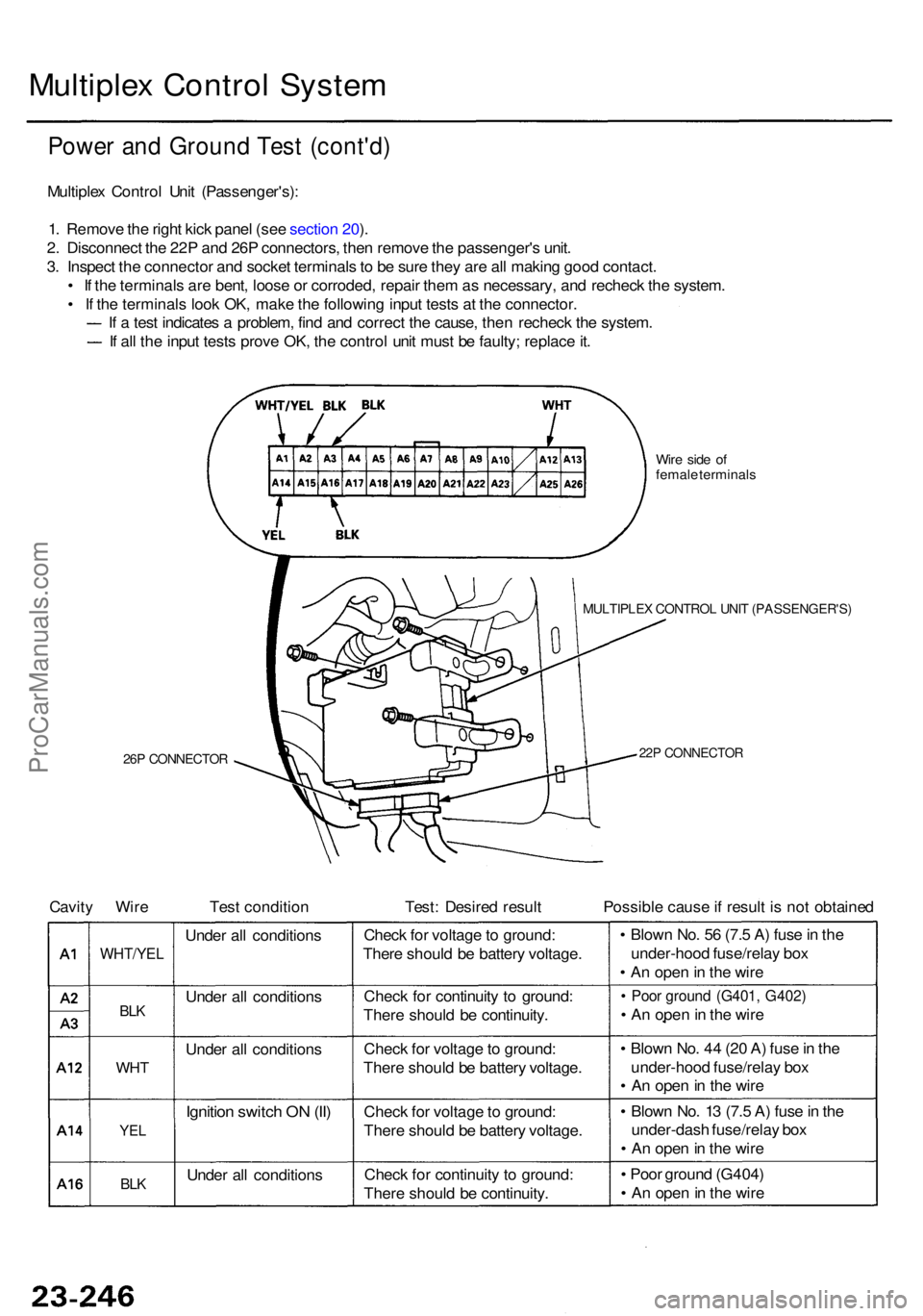
Multiplex Contro l Syste m
Power an d Groun d Tes t (cont'd )
Multiplex Contro l Uni t (Passenger's) :
1 . Remov e th e righ t kic k pane l (se e sectio n 20 ).
2 . Disconnec t th e 22 P an d 26 P connectors , the n remov e th e passenger' s unit .
3 . Inspec t th e connecto r an d socke t terminal s to b e sur e the y ar e al l makin g goo d contact .
• I f th e terminal s ar e bent , loos e o r corroded , repai r the m a s necessary , an d rechec k th e system .
• I f th e terminal s loo k OK , mak e th e followin g inpu t test s a t th e connector .
I f a tes t indicate s a problem , fin d an d correc t th e cause , the n rechec k th e system .
If al l th e inpu t test s prov e OK , th e contro l uni t mus t b e faulty ; replac e it .
Wir e sid e o f
femal e terminal s
26P CONNECTO R
MULTIPLEX CONTRO L UNI T (PASSENGER'S )
22P CONNECTO R
Cavity Wir e Tes t conditio n Test : Desire d resul t Possibl e caus e if resul t i s no t obtaine d
Unde r al l condition s
Unde r al l condition s
Unde r al l condition s
Ignition switc h O N (II )
Unde r al l condition s
WHT/YEL
BLK
WH T
YEL
BLK
Chec k fo r voltag e to ground :
Ther e shoul d b e batter y voltage .
Chec k fo r continuit y t o ground :
Ther e shoul d b e continuity .
Chec k fo r voltag e to ground :
Ther e shoul d b e batter y voltage .
Chec k fo r voltag e to ground :
Ther e shoul d b e batter y voltage .
Chec k fo r continuit y t o ground :
Ther e shoul d b e continuity . •
Blow n No . 5 6 (7. 5 A ) fus e in th e
under-hoo d fuse/rela y bo x
• A n ope n in th e wir e
• Poo r groun d (G401 , G402 )
• A n ope n in th e wir e
• Blow n No . 4 4 (2 0 A ) fus e in th e
under-hoo d fuse/rela y bo x
• A n ope n in th e wir e
• Blow n No . 1 3 (7. 5 A ) fus e in th e
under-das h fuse/rela y bo x
• A n ope n in th e wir e
• Poo r groun d (G404 )
• A n ope n in th e wir e
ProCarManuals.com
Page 1649 of 1954
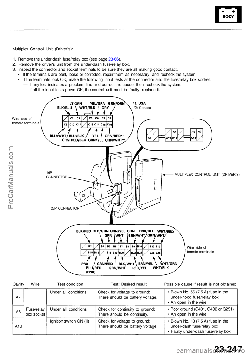
Multiplex Contro l Uni t (Driver's) :
1 . Remov e th e under-das h fuse/rela y bo x (se e pag e 23-66 ).
2 . Remov e th e driver' s uni t fro m th e under-das h fuse/rela y box .
3 . Inspec t th e connecto r an d socke t terminal s t o b e sur e the y ar e al l makin g goo d contact .
• I f th e terminal s ar e bent , loos e o r corroded , repai r the m a s necessary , an d rechec k th e system .
• I f th e terminal s loo k OK , mak e th e followin g inpu t test s a t th e connecto r an d th e fuse/rela y bo x socket .
— If an y tes t indicate s a problem , fin d an d correc t th e cause , the n rechec k th e system .
— If al l th e inpu t test s prov e OK , th e contro l uni t mus t b e faulty ; replac e it .
Wir e sid e o ffemal e terminal s
MULTIPLE X CONTRO L UNI T (DRIVER'S )16PCONNECTO R
26 P CONNECTO R *2
: Canad a
Cavity Wir e Tes t conditio n Test : Desire d resul t Possibl e caus e if resul t i s no t obtaine d
Unde r al l condition s
Unde r al l condition s
Ignition switc h O N (II )
Chec k fo r voltag e t o ground :
Ther e shoul d b e batter y voltage .
Chec k fo r continuit y t o ground :
Ther e shoul d b e continuity .
Chec k fo r voltag e t o ground :
Ther e shoul d b e batter y voltage .
Fuse/rela y
box socke t •
Blow n No . 5 6 (7. 5 A ) fus e in th e
under-hoo d fuse/rela y bo x
• A n ope n i n th e wir e
• Poo r groun d (G401 , G40 2 o r G251 )
• A n ope n in th e wir e
• Blow n No . 1 3 (7. 5 A ) fus e in th e
under-das h fuse/rela y bo x
• Fault y under-das h fuse/rela y bo x
A13
A8
A7
Wir e sid e o ffemal e terminal s
ProCarManuals.com