Page 362 of 1954
Cruise Contro l
Actuator/Cabl e Replacemen t
1. Disconnec t th e 4 P connecto r fro m th e actuator .
2 . Remov e th e thre e mountin g bolt s an d th e actuato r
wit h th e bracket .
4P CONNECTO R
3. Remov e th e vacuu m hose .
4 . Remov e th e thre e nuts .
5 . Disconnec t th e actuato r cabl e fro m th e actuato r ro d
b y releasin g th e cli p fro m th e ro d wit h a screwdrive r
a s shown .
CLIP
ACTUATO RROD ACTUATO
RCABLE NUT S
6. Loose n th e locknut , the n disconnec t th e actuato r
cabl e fro m th e throttl e linkage .
ADJUSTIN GNUTLOCKNU T
ACTUATO RCABLE
CABL E
BRACKE TTHROTTL ELINKAGE
7. Instal l i n th e revers e orde r o f removal , an d adjus t
fre e pla y a t th e throttl e linkag e afte r connectin g th e
actuato r cable .
MOUNTIN G BOLT S
VACUU
M HOS E
MOUNTIN G BOL T
ProCarManuals.com
Page 363 of 1954
Actuator Cable Adjustment
1. Check that the actuator cable moves smoothly with
no binding or sticking.
2. Measure the amount of movement of the output
linkage until the engine speed starts to increase. At
first, the output linkage should be located at the
fully closed position. Free play should be 5 ± 0.5 mm
(0.20
±
0.02 in).
OUTPUT
LINKAGE
ADJUSTING
NUT
FREE PLAY: 5 ± 0.5 mm (0.20 ± 0.02 in)
ACTUATOR
CABLE
3. If the free play is not within specs, move the cable to
the point where the engine speed starts to increase,
and tighten the locknut and adjusting nut.
CABLE
BRACKET
ADJUSTING
NUT
LOCKNUT
ACTUATOR
CABLE
4.
Turn the adjusting nut until it is 5 ± 0.5 mm (0.20 ±
0.02 in) away from the bracket.
5 ± 0.5 mm
(0.20
±
0.02
in)
CABLE
BRACKET
ADJUSTING
NUT
5.
Pull the cable so that the adjusting nut touches the
bracket, and tighten the locknut.
ADJUSTING
NUT
LOCKNUTProCarManuals.com
Page 366 of 1954

Engine Removal/Installatio n
Removal (cont'd )
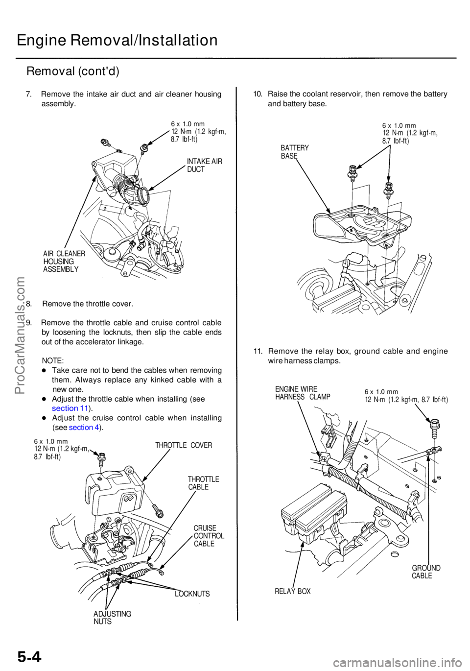
7. Remov e th e intak e ai r duc t an d ai r cleane r housin g
assembly .
6 x 1. 0 m m12 N- m (1. 2 kgf-m ,
8. 7 Ibf-ft )
INTAK E AI RDUC T
AIR CLEANE RHOUSINGASSEMBL Y
8. Remov e th e throttl e cover .
9 . Remov e th e throttl e cabl e an d cruis e contro l cabl e
b y loosenin g th e locknuts , the n sli p th e cabl e end s
ou t o f th e accelerato r linkage .
NOTE:
Take car e no t t o ben d th e cable s whe n removin g
them . Alway s replac e an y kinke d cabl e wit h a
ne w one .
Adjus t th e throttl e cabl e whe n installin g (se e
sectio n 11 ).
Adjus t th e cruis e contro l cabl e whe n installin g
(se e sectio n 4 ).
6 x 1. 0 m m12 N- m (1. 2 kgf-m ,8.7 Ibf-ft ) THROTTL
E COVE R
THROTTL E
CABL E
CRUIS E
CONTRO LCABLE
LOCKNUT S
ADJUSTIN GNUTS
10. Rais e th e coolan t reservoir , the n remov e th e batter y
an d batter y base .
11 . Remov e th e rela y box , groun d cabl e an d engin e
wir e harnes s clamps .
ENGINE WIR EHARNES S CLAM P6 x 1. 0 m m12 N- m (1. 2 kgf-m , 8. 7 Ibf-ft )
GROUN DCABLE
RELA Y BO X
BATTER
Y
BAS E
6 x 1. 0 m m12 N- m (1. 2 kgf-m ,
8. 7 Ibf-ft )
ProCarManuals.com
Page 369 of 1954
22. Disconnect the spark plug voltage detection module
connector, and remove the engine ground cables.
6 x 1.0 mm
12 N-m (1.2 kgf-m,
8.7 Ibf-ft)
GROUND
CABLES
SPARK PLUG VOLTAGE
DETECTION MODULE
CONNECTOR
23. Remove the vacuum hoses.
VACUUM
HOSES
24. Loosen the mounting bolt, lock bolt and adjusting
rod, then remove the alternator belt.
ADJUSTING
ROD
LOCK BOLT
8 x
1.25
mm
22 N-m (2.2 kgf-m,
16 Ibf-ft)
ALTERNATOR
BELT
MOUNTING BOLT
10 x
1.25
mm
44 N-m (4.5 kgf-m,
33 Ibf-ft)
25.
Loosen the idler pulley center nut and adjusting
bolt, then remove the air conditioning (A/C) com-
pressor belt.
ADJUSTING
BOLT
IDLER PULLEY
CENTER NUT
10 x
1.25
mm
44 N-m (4.5 kgf-m,
33 Ibf-ft)
A/C COMPRESSOR
BELTProCarManuals.com
Page 370 of 1954

Engine Removal/Installatio n
Removal (cont'd )
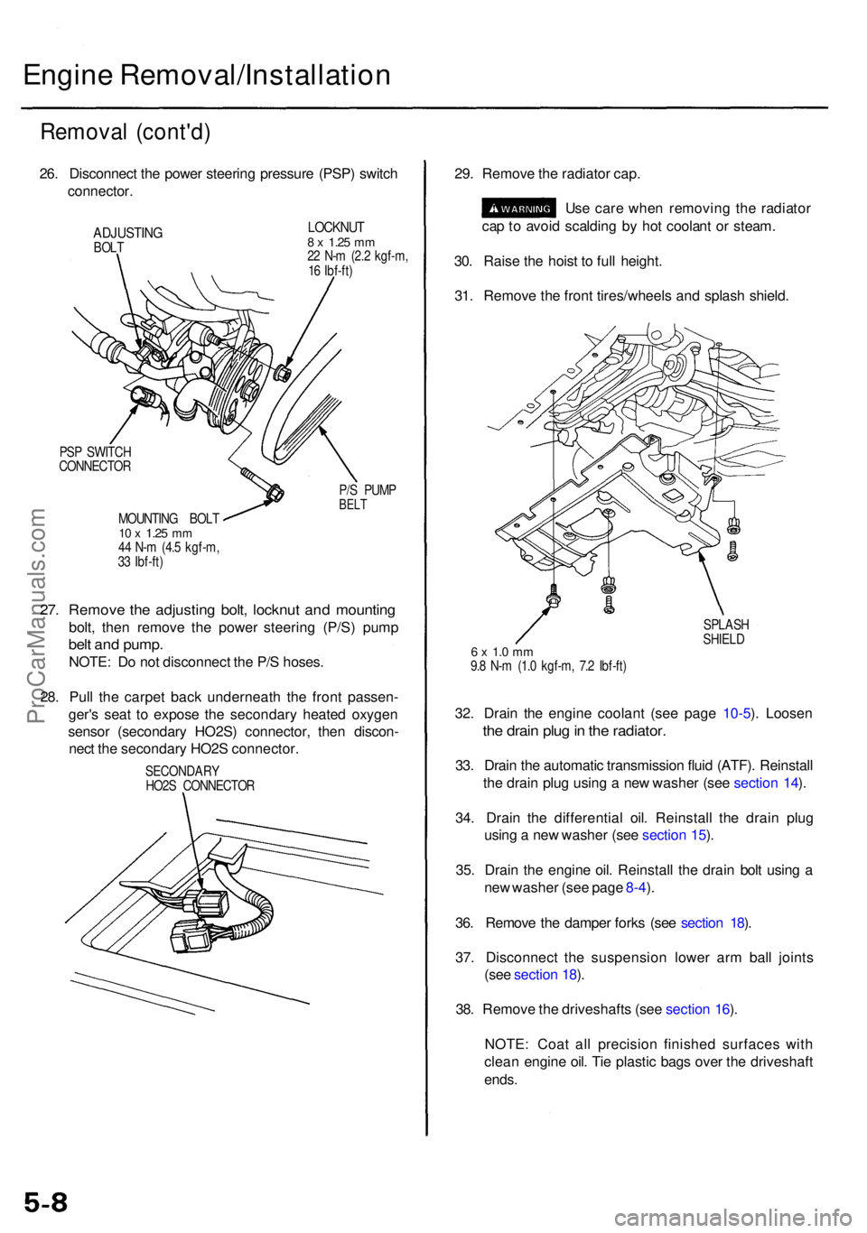
26. Disconnec t th e powe r steerin g pressur e (PSP ) switc h
connector .
ADJUSTIN GBOLT
LOCKNU T8 x 1.2 5 mm22 N- m (2. 2 kgf-m ,
1 6 Ibf-ft )
PS P SWITC H
CONNECTO R
P/S PUM P
BELTMOUNTIN G BOL T10 x 1.2 5 mm44 N- m (4. 5 kgf-m ,
3 3 Ibf-ft )
27. Remov e th e adjustin g bolt , locknu t an d mountin g
bolt, the n remov e th e powe r steerin g (P/S ) pum p
belt an d pump .
NOTE: D o no t disconnec t th e P/ S hoses .
28 . Pul l th e carpe t bac k underneat h th e fron t passen -
ger' s sea t t o expos e th e secondar y heate d oxyge n
senso r (secondar y HO2S ) connector , the n discon -
nec t th e secondar y HO2 S connector . 29
. Remov e th e radiato r cap .
Us e car e whe n removin g th e radiato r
ca p to avoi d scaldin g b y ho t coolan t o r steam .
30 . Rais e th e hois t t o ful l height .
31 . Remov e th e fron t tires/wheel s an d splas h shield .
SPLAS H
SHIEL D
6 x 1. 0 m m9.8 N- m (1. 0 kgf-m , 7. 2 Ibf-ft )
32. Drai n th e engin e coolan t (se e pag e 10-5 ). Loose n
the drai n plu g in th e radiator .
33. Drai n th e automati c transmissio n flui d (ATF) . Reinstal l
th e drai n plu g usin g a ne w washe r (se e sectio n 14 ).
34 . Drai n th e differentia l oil . Reinstal l th e drai n plu g
usin g a ne w washer (see sectio n 15 ).
35 . Drai n th e engin e oil . Reinstal l th e drai n bol t usin g a
ne w washe r (se e pag e 8-4 ).
36 . Remov e th e dampe r fork s (se e sectio n 18 ).
37 . Disconnec t th e suspensio n lowe r ar m bal l joint s
(se e sectio n 18 ).
38 . Remov e th e driveshaft s (se e sectio n 16 ).
NOTE : Coa t al l precisio n finishe d surface s wit h
clea n engin e oil . Ti e plasti c bag s ove r th e driveshaf t
ends.
SECONDAR Y
HO2 S CONNECTO R
ProCarManuals.com
Page 371 of 1954

39. Disconnect the compressor clutch connector, then
remove the A/C compressor. Do not disconnect the
A/C hoses.
COMPRESSOR CLUTCH
CONNECTOR
A/C COMPRESSOR
8 x
1.25
mm
22 N-m (2.2 kgf-m,
16 Ibf-ft)
40. Disconnect the vehicle speed sensor (VSS) connector,
then remove the VSS/power steering speed sensor.
Do not disconnect the fluid hoses.
6 x 1.0 mm
12 N-m (1.2 kgf-m,
8.7 Ibf-ft)
VSS CONNECTOR
VSS/POWER STEERING
SPEED SENSOR
41. Remove the transmission stop collars.
42. Remove exhaust pipe A.
GASKETS
Replace.
GASKET
Replace.
EXHAUST
PIPE A
SELF-LOCKING NUT
10 x
1.25
mm
54 N-m (5.5 kgf-m,
40 Ibf-ft)
Replace.
10 x
1.25
mm
38 N-m (3.9 kgf-m,
28 Ibf-ft)
SELF-LOCKING NUT
10 x
1.25
mm
54 N-m (5.5 kgf-m,
40 Ibf-ft)
Replace.
TRANSMISSION STOP
COLLAR
43. Remove the wire harness cover and grommet, then
remove the three way catalytic converter (TWC).
SELF-LOCKING NUT
10 x
1.25
mm
33 N-m (3.4 kgf-m,
25 Ibf-ft)
Replace.
GROMMET
WIRE HARNESS
COVER
GASKET
Replace.
TWC
6 x 1.0 mm
9.8 N-m (1.0 kgf-m,
7.2 Ibf-ft)
SELF-LOCKING NUT
8 x
1.25
mm
22 N-m (2.2 kgf-m, 16 Ibf-ft)
Replace.ProCarManuals.com
Page 372 of 1954

Engine Removal/Installatio n
Removal (cont'd )
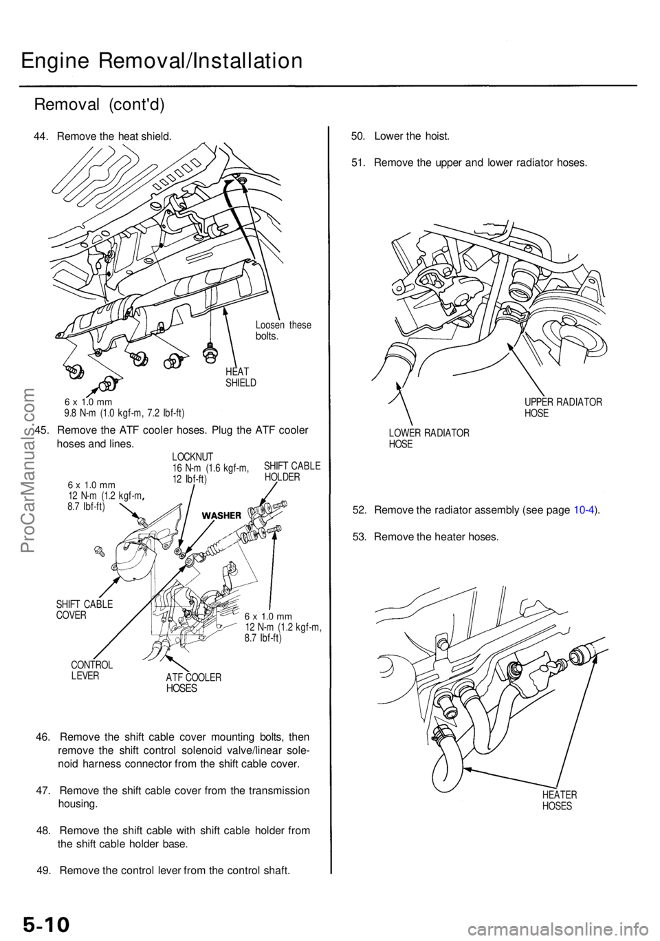
44. Remov e th e hea t shield .
Loosen thes ebolts.
HEATSHIEL D
6 x 1. 0 m m9.8 N- m (1. 0 kgf-m , 7. 2 Ibf-ft )
45. Remov e th e AT F coole r hoses . Plu g th e AT F coole r
hose s an d lines .
6 x 1. 0 m m12 N- m (1. 2 kgf- m
8. 7 Ibf-ft ) LOCKNU
T
1 6 N- m (1. 6 kgf-m ,
1 2 Ibf-ft ) SHIF
T CABL E
HOLDE R
SHIF T CABL E
COVE R
CONTRO L
LEVER
6 x 1. 0 m m12 N- m (1. 2 kgf-m ,
8. 7 Ibf-ft )
AT F COOLE R
HOSES
46. Remov e th e shif t cabl e cove r mountin g bolts , the n
remov e th e shif t contro l solenoi d valve/linea r sole -
noi d harnes s connecto r fro m th e shif t cabl e cover .
47 . Remov e th e shif t cabl e cove r fro m th e transmissio n
housing .
48 . Remov e th e shif t cabl e wit h shif t cabl e holde r fro m
th e shif t cabl e holde r base .
49 . Remov e th e contro l leve r fro m th e contro l shaft . 50
. Lowe r th e hoist .
51 . Remov e th e uppe r an d lowe r radiato r hoses .
UPPER RADIATO R
HOS E
LOWE R RADIATO R
HOS E
52. Remov e th e radiato r assembl y (se e pag e 10-4 ).
53 . Remov e th e heate r hoses .
HEATE RHOSES
ProCarManuals.com
Page 373 of 1954
54. Attach the chain hoist to the engine.
FUEL PRESSURE REGULATOR
29 N-m (3.0 kgf-m, 22 Ibf-ft)
NOTE: Loosen the locknut on the
fuel pressure regulator, then turn
the fuel pressure regulator 180°.ProCarManuals.com