1996 ACURA RL KA9 engine
[x] Cancel search: enginePage 1215 of 1954
Troubleshooting
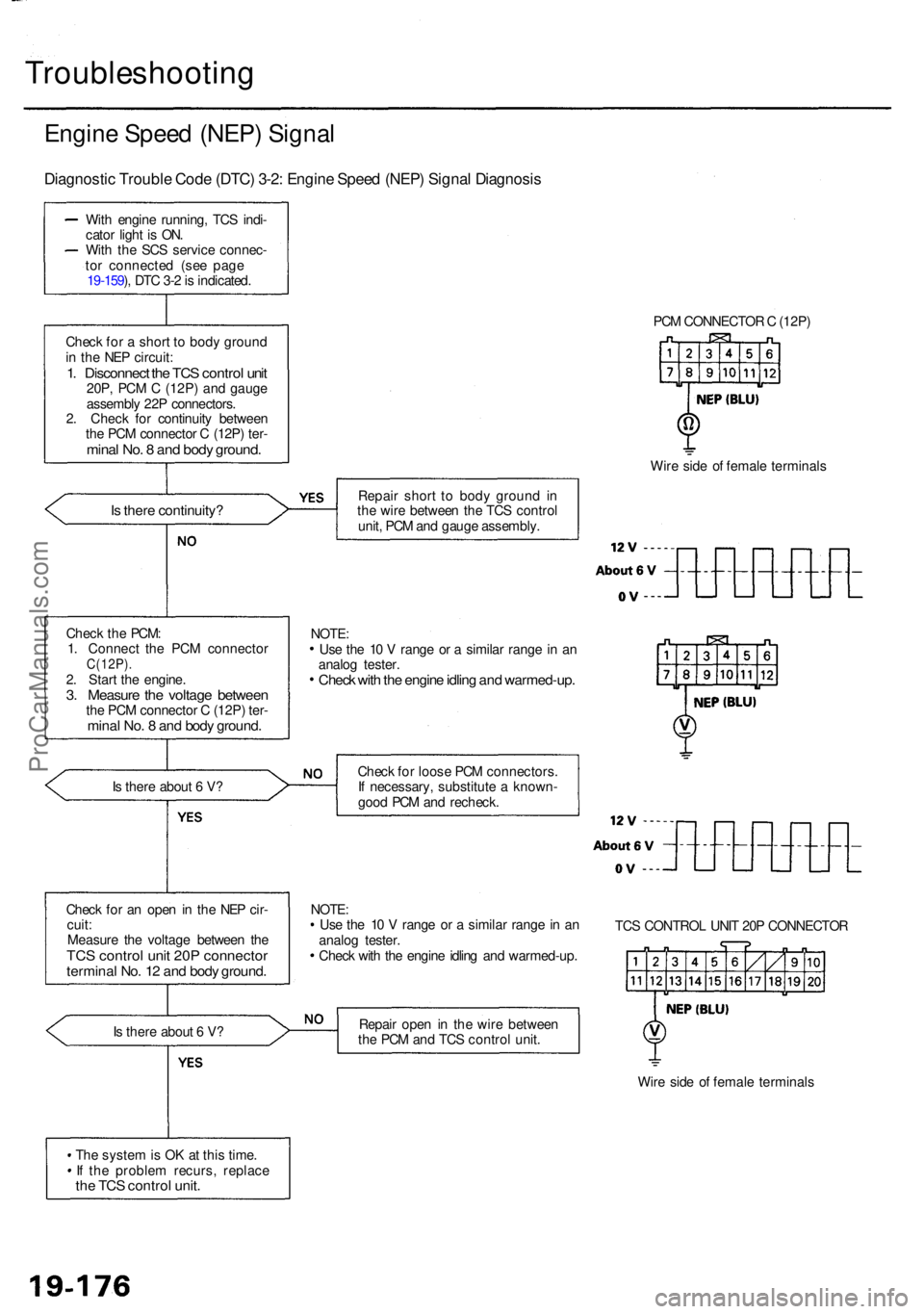
Engine Spee d (NEP ) Signa l
Diagnosti c Troubl e Cod e (DTC ) 3-2 : Engin e Spee d (NEP ) Signa l Diagnosi s
With engin e running , TC S indi -
cato r ligh t i s ON .
Wit h th e SC S servic e connec -
to r connecte d (se e pag e
19-159 ), DT C 3- 2 is indicated .
Chec k fo r a shor t t o bod y groun d
i n th e NE P circuit :
1. Disconnec t th e TC S contro l uni t20P , PC M C (12P ) an d gaug e
assembl y 22 P connectors .
2 . Chec k fo r continuit y betwee n
th e PC M connecto r C (12P ) ter -
mina l No . 8 an d bod y ground .
Is ther e continuity ?
Is ther e abou t 6 V ?
Chec k fo r a n ope n in th e NE P cir -
cuit :
Measur e th e voltag e betwee n th e
TC S contro l uni t 20 P connecto rterminal No . 1 2 an d bod y ground .
Is ther e abou t 6 V ?
Th e syste m is O K a t thi s time .
I f th e proble m recurs , replac e
the TC S contro l unit .
PCM CONNECTO R C (12P )
Wir e sid e o f femal e terminal s
Repai r shor t t o bod y groun d i n
th e wir e betwee n th e TC S contro l
unit , PC M an d gaug e assembly .
Chec k fo r loos e PC M connectors .
I f necessary , substitut e a known -
goo d PC M an d recheck .
NOTE :
Us e th e 1 0 V rang e o r a simila r rang e in a n
analo g tester .
Chec k wit h th e engin e idlin g an d warmed-up .TC
S CONTRO L UNI T 20 P CONNECTO R
Repai r ope n in th e wir e betwee n
th e PC M an d TC S contro l unit .
Wire sid e o f femal e terminal s
Chec
k th e PCM :
1 . Connec t th e PC M connecto r
C(12P).2. Star t th e engine .3. Measur e th e voltag e betwee nthe PC M connecto r C (12P ) ter -mina l No . 8 an d bod y ground .
Use th e 1 0 V rang e o r a simila r rang e in a n
analo g tester .
Check wit h th e engin e idlin g an d warmed-up .
NOTE:
ProCarManuals.com
Page 1223 of 1954
Troubleshooting
ABS Dow n
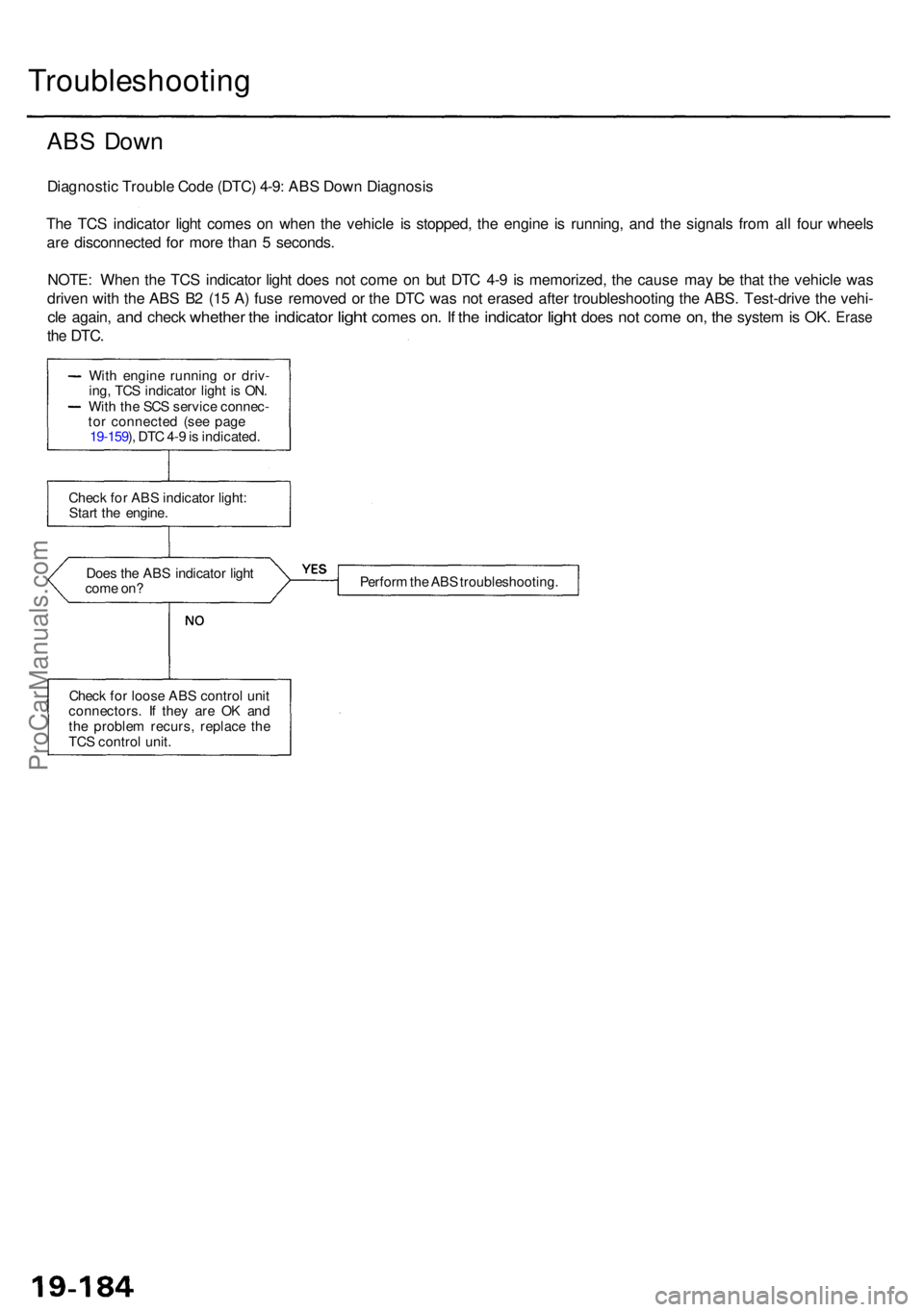
Diagnosti c Troubl e Cod e (DTC ) 4-9 : AB S Dow n Diagnosi s
Th e TC S indicato r ligh t come s o n whe n th e vehicl e i s stopped , th e engin e i s running , an d th e signal s fro m al l fou r wheel s
ar e disconnecte d fo r mor e tha n 5 seconds .
NOTE : Whe n th e TC S indicato r ligh t doe s no t com e o n bu t DT C 4- 9 i s memorized , th e caus e ma y b e tha t th e vehicl e wa s
drive n wit h th e AB S B 2 (1 5 A ) fus e remove d o r th e DT C wa s no t erase d afte r troubleshootin g th e ABS . Test-driv e th e vehi -
cle again , and chec k whethe r the indicato r light come s on. I f th e indicato r light doe s not com e on, th e syste m is OK . Eras e
the DTC .
Does th e AB S indicato r ligh t
com e on ? Perfor
m th e AB S troubleshooting .
Chec k fo r loos e AB S contro l uni t
connectors . I f the y ar e O K an d
th e proble m recurs , replac e th e
TC S contro l unit .
Chec
k fo r AB S indicato r light :
Star t th e engine .
Wit
h engin e runnin g o r driv -
ing , TC S indicato r ligh t i s ON .
Wit h th e SC S servic e connec -
to r connecte d (se e pag e
19-159 ), DT C 4- 9 is indicated .
ProCarManuals.com
Page 1225 of 1954
Troubleshooting
Ignition Switc h (IG1 ) Signa l
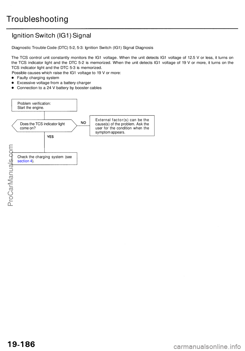
Diagnosti c Troubl e Cod e (DTC ) 5-2 , 5-3 : Ignitio n Switc h (IG1 ) Signa l Diagnosi s
Th e TC S contro l uni t constantl y monitor s th e IG 1 voltage . Whe n th e uni t detect s IG 1 voltag e o f 12. 5 V or less , i t turn s o n
th e TC S indicato r ligh t an d th e DT C 5- 2 i s memorized . Whe n th e uni t detect s IG 1 voltag e o f 1 9 V or more , i t turn s o n th e
TC S indicato r ligh t an d th e DT C 5- 3 is memorized .
Possibl e cause s whic h rais e th e IG 1 voltag e to 1 9 V or more :
Fault y chargin g syste m
Excessiv e voltag e fro m a batter y charge r
Connectio n t o a 24 V batter y b y booste r cable s
Proble m verification :
Star t th e engine .
Does th e TC S indicato r ligh tcom e on ? Externa
l factor(s ) ca n b e th e
cause(s ) o f th e problem . As k th e
use r fo r th e conditio n whe n th e
sympto m appears .
Chec k th e chargin g syste m (se e
sectio n 4 ).
ProCarManuals.com
Page 1226 of 1954
TCS Contro l Valv e Actuato r
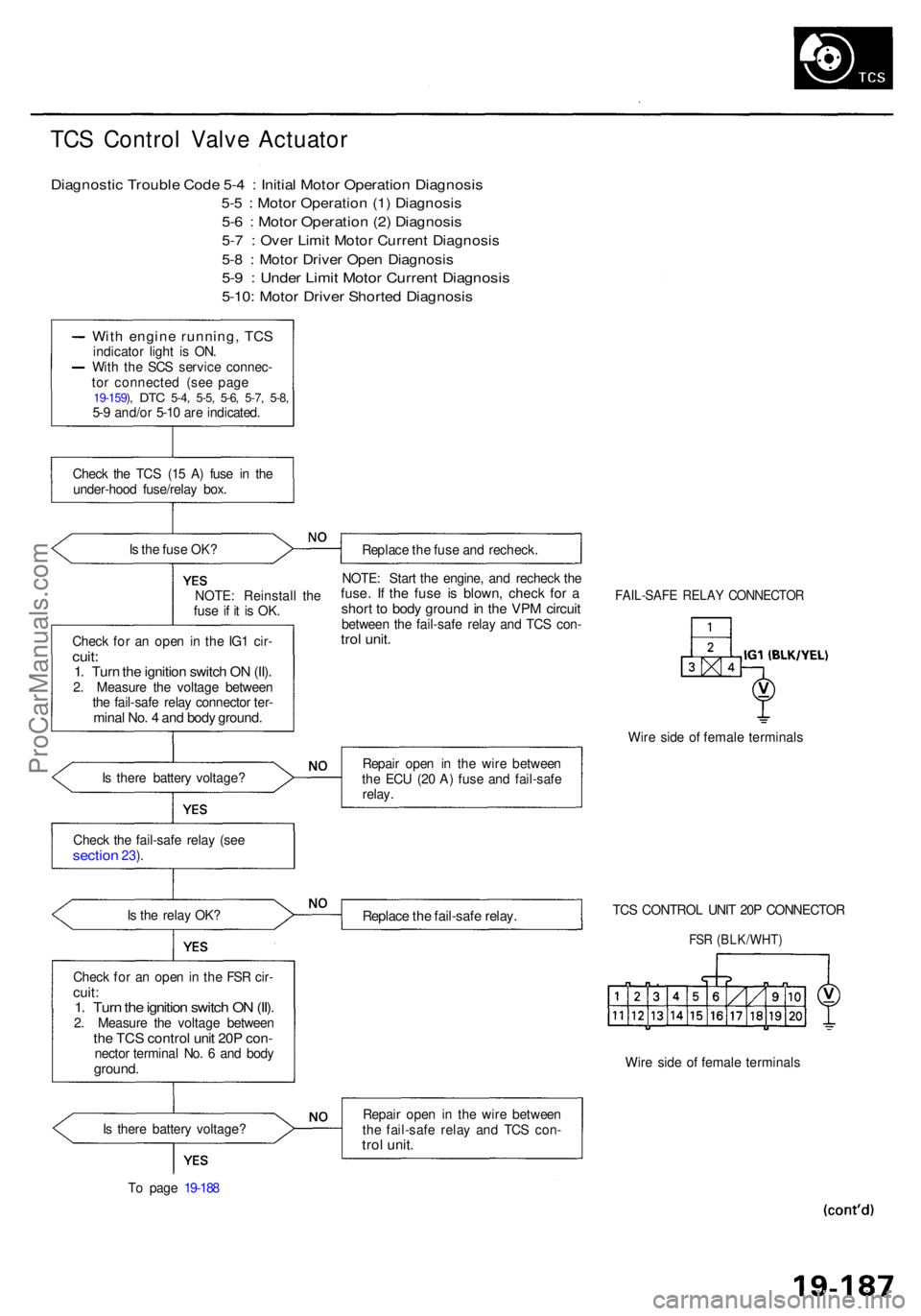
Diagnosti c Troubl e Cod e 5- 4 : Initia l Moto r Operatio n Diagnosi s
5-5 : Moto r Operatio n (1 ) Diagnosi s
5-6 : Moto r Operatio n (2 ) Diagnosi s
5-7 : Ove r Limi t Moto r Curren t Diagnosi s
5-8 : Moto r Drive r Ope n Diagnosi s
5-9 : Unde r Limi t Moto r Curren t Diagnosi s
5-10: Moto r Drive r Shorte d Diagnosi s
With engin e running , TC Sindicato r ligh t i s ON .
Wit h th e SC S servic e connec -
to r connecte d (se e pag e
19-159 ), DT C 5-4 , 5-5 , 5-6 , 5-7 , 5-8 ,5-9 and/o r 5-1 0 ar e indicated .
Chec k th e TC S (1 5 A ) fus e i n th e
under-hoo d fuse/rela y box .
I s th e fus e OK ?
Replace th e fus e an d recheck .
NOTE : Reinstal l th e
fus e i f i t i s OK .
Chec k fo r a n ope n i n th e IG 1 cir -
cuit:1. Tur n th e ignitio n switc h O N (II) .2. Measur e th e voltag e betwee n
th e fail-saf e rela y connecto r ter -
mina l No . 4 an d bod y ground .
NOTE: Star t th e engine , an d rechec k th efuse . I f th e fus e i s blown , chec k fo r ashor t t o bod y groun d in th e VP M circui tbetwee n th e fail-saf e rela y an d TC S con -trol unit .
FAIL-SAF E RELA Y CONNECTO R
Wire sid e o f femal e terminal s
I s ther e batter y voltage ? Repai
r ope n i n th e wir e betwee n
th e EC U (2 0 A ) fus e an d fail-saf e
relay .
Chec k th e fail-saf e rela y (se e
sectio n 23).
I s th e rela y OK ?
Replac e th e fail-saf e relay .TCS CONTRO L UNI T 20 P CONNECTO R
FSR (BLK/WHT )
Check fo r a n ope n in th e FS R cir -cuit :1. Tur n th e ignitio n switc h O N (II) .2. Measur e th e voltag e betwee nthe TC S contro l uni t 20 P con -necto r termina l No . 6 an d bod yground .Wire sid e o f femal e terminal s
I s ther e batter y voltage ?
T o pag e 19-18 8 Repai
r ope n i n th e wir e betwee n
th e fail-saf e rela y an d TC S con -
trol unit .
ProCarManuals.com
Page 1230 of 1954
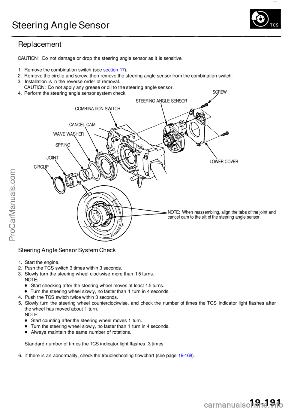
Steering Angl e Senso r
Replacemen t
SCREW
CAUTION : D o no t damag e o r dro p th e steerin g angl e senso r a s it i s sensitive .
1 . Remov e th e combinatio n switc h (se e sectio n 17 ).
2 . Remov e th e circli p an d screw , the n remov e th e steerin g angl e senso r fro m th e combinatio n switch .
3 . Installatio n i s i n th e revers e orde r o f removal .
CAUTION : D o no t appl y an y greas e o r oi l t o th e steerin g angl e sensor .
4 . Perfor m th e steerin g angl e senso r syste m check .
STEERIN G ANGL E SENSO R
COMBINATIO N SWITC H
CANCE L CA M
WAV E WASHE R
SPRING
LOWER COVE RJOINT
CIRCLI P
NOTE: Whe n reassembling , alig n th e tab s o f th e join t an dcance l ca m to th e sli t o f th e steerin g angl e sensor .
Steering Angl e Senso r Syste m Chec k
1. Star t th e engine .
2 . Pus h th e TC S switc h 3 time s withi n 3 seconds .
3 . Slowl y tur n th e steerin g whee l clockwis e mor e tha n 1. 5 turns .
NOTE :
Start checkin g afte r th e steerin g whee l move s a t leas t 1. 5 turns .
Tur n th e steerin g whee l slowly , n o faste r tha n 1 tur n in 4 seconds .
4 . Pus h th e TC S switc h twic e withi n 3 seconds .
5 . Slowl y tur n th e steerin g whee l counterclockwise , an d chec k th e numbe r o f time s th e TC S indicato r ligh t flashe s afte r
th e whee l ha s move d abou t 1 turn .
NOTE :
Start countin g afte r th e steerin g whee l move s 1 turn .
Tur n th e steerin g whee l slowly , n o faste r tha n 1 tur n in 4 seconds .
Alway s maintai n th e sam e numbe r o f rotations .
Standar d numbe r o f time s th e TC S indicato r ligh t flashes : 3 time s
6 . I f ther e is a n abnormality , chec k th e troubleshootin g flowchar t (se e pag e 19-168 ).
ProCarManuals.com
Page 1239 of 1954
Troubleshooting Precaution s
System Indicator s
If th e syste m is OK , th e AB S indicato r goe s of f onc e afte r turnin g th e ignitio n switc h O N (II ) withou t startin g th e engine ,
an d the n com e o n agai n an d g o of f severa l second s late r afte r startin g th e engine . Thi s occur s becaus e th e VS A contro l
uni t i s turne d o n b y th e IG 2 powe r source .
Th e AB S indicato r o r VS A syste m indicato r come s o n whe n th e VS A contro l uni t detect s a proble m in th e system .
Th e AB S indicato r o r VS A syste m indicato r wil l als o com e o n unde r thes e conditions , eve n thoug h th e syste m is oper -
atin g properly :
— Th e vehicl e goe s int o a spi n
— Th e AB S continue s t o operat e fo r a lon g tim e
— Th e vehicl e is subjecte d to a n electrica l signa l disturbanc e
I f ther e is a faul t i n th e PGM-F I system , onl y th e VS A syste m indicato r come s on .
Th e VS A Activatio n Indicato r wil l flas h whe n onl y th e driv e wheel s rotat e o r on e o f th e driv e wheel s is stuck . Whe n thi s
occurs , th e AB S indicato r an d VS A syste m indicato r d o no t com e on .
T o determin e th e actua l caus e o f th e problem , questio n th e custome r abou t th e problem , takin g thes e condition s int o con -
sideration .
Whe n a proble m is detecte d an d th e AB S o r VS A indicato r come s on , ther e ar e case s whe n th e indicato r stay s o n unti l
th e ignitio n switc h i s turne d OFF , an d case s whe n th e indicato r goe s of f automaticall y whe n th e syste m return s t o nor -
mal . Fo r DT C 6 1 an d 62 , th e indicato r goe s of f automaticall y whe n th e syste m return s t o normal . Fo r al l othe r codes ,
th e indicato r stay s o n unti l th e ignitio n switc h is turne d OFF .
Fo r DTC s 12 , 14 , 16 , 18 , 51 , 52 , 53 , 66 , 6 8 an d 84 , th e AB S indicato r goe s of f whe n th e vehicl e is drive n agai n an d th e
syste m is O K afte r th e ignitio n switc h is turne d fro m OF F to O N (II) . However , i f th e DT C is cleared , th e CP U reset s an d
th e indicato r goe s of f righ t afte r th e engin e is starte d if th e syste m is OK .
Th e AB S is no t operationa l whe n th e AB S indicato r i s ON ; th e VS A is no t operationa l whe n th e VS A indicato r i s ON .
Whe n th e VS A indicato r an d MI L ar e bot h ON , troubleshoo t th e PGM-F I syste m first .
Diagnosti c Troubl e Cod e (DTC )
Th e memor y ca n hol d an y numbe r o f DTCs . However , whe n th e sam e DT C is detecte d mor e tha n once , th e mor e recen t
DT C is writte n ove r th e earlie r one . Therefore , whe n th e sam e proble m is detecte d repeatedly , i t i s memorize d a s a sin -
gle DTC .
The DTC s ar e indicate d in ascendin g numbe r order , no t i n th e orde r the y occur .
Th e DTC s ar e memorize d in th e EEPRO M (non-volatil e memory) . Therefore , th e memorize d DTC s canno t b e cancele d
b y disconnectin g th e battery . Perfor m th e specifie d procedure s to clea r th e DTCs .
Self-diagnosi s
Self-diagnosis can be classifie d int o tw o categories :
— Initia l diagnosis : Performe d righ t afte r th e engin e start s an d unti l th e AB S o r VS A indicato r goe s off .
— Regula r diagnosis : Performe d righ t afte r th e initia l diagnosi s unti l th e ignitio n switc h is turne d OFF .
When a proble m is detecte d b y self-diagnosis , th e VS A contro l uni t shift s to fail-saf e mode .
Kickbac k
The pum p moto r operate s whe n th e AB S is functioning , an d th e flui d in th e reservoi r i s force d ou t t o th e maste r cylinder ,
causing kickbac k a t th e brak e pedal .
Pum p Moto r
Th e pum p moto r operate s whe n th e AB S is functioning .
The VS A contro l uni t check s th e pum p moto r operatio n durin g initia l diagnosi s whe n th e vehicl e is started .
You ma y hea r th e moto r operat e a t thi s time , bu t i t i s normal .
Brak e Flui d Replacement/Ai r Bleedin g
Brak e flui d replacemen t an d ai r bleedin g procedure s ar e identica l t o th e procedure s us e o n vehicle s no t equippe d wit h
VSA . T o eas e bleeding , star t wit h th e fron t wheels .
ProCarManuals.com
Page 1256 of 1954
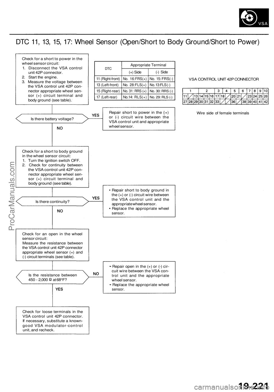
DTC 11, 13, 15, 17: Wheel Sensor (Open/Short to Body Ground/Short to Power)
Check for a short to power in the
wheel sensor circuit:
1. Disconnect the VSA control
unit 42P connector.
2. Start the engine.
3. Measure the voltage between
the VSA control unit 42P con-
nector appropriate wheel sen-
sor (+) circuit terminal and
body ground (see table).
DTC
11 (Right-front)
13 (Left-front)
15 (Right-rear)
17 (Left-rear)
Appropriate Terminal
(+) Side
No. 16:FRS(+)
No. 28:FLS(+)
No. 31: RRS (+)
No.14: RLS(+)
(-) Side
No. 15: FRS(-)
No. 13:FLS (-)
No. 30:
RRS
(-)
No. 29: RLS (-)
VSA CONTROL UNIT 42P CONNECTOR
Is there battery voltage?
Repair short to power in the {+)
or (-) circuit wire between the
VSA control unit and appropriate
wheel sensor.
Wire side of female terminals
Check for a short to body ground
in the wheel sensor circuit:
1. Turn the ignition switch OFF.
2. Check for continuity between
the VSA control unit 42P con-
nector appropriate wheel sen-
sor (+) circuit terminal and
body ground (see table).
Is there continuity?
Repair short to body ground in
the (+) or (-) circuit wire between
the VSA control unit and the
appropriate wheel sensor.
Replace the appropriate wheel
sensor.
Check for an open in the wheel
sensor circuit:
Measure the resistance between
the VSA control unit 42P connector
appropriate wheel sensor (+) and
(-) circuit terminals (see table).
Is the resistance between
450 - 2,000 at 68°F?
• Repair open in the (+) or (-) cir-
cuit wire between the VSA con-
trol unit and the appropriate
wheel sensor.
• Replace the appropriate wheel
sensor.
Check for loose terminals in the
VSA control unit 42P connector.
If necessary, substitute a known-
good VSA modulator-control
unit, and recheck.ProCarManuals.com
Page 1271 of 1954
Troubleshooting
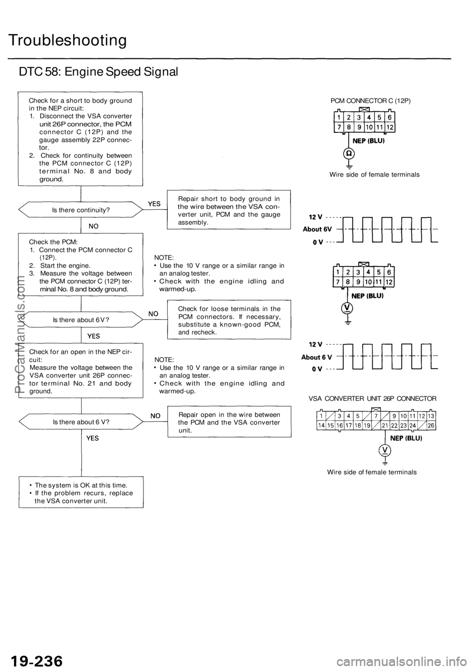
DTC 58: Engine Speed Signal
Check for a short to body ground
in the NEP circuit:
1. Disconnect the VSA converter
unit 26P connector, the PCM
connector C (12P) and the
gauge assembly 22P connec-
tor.
2. Check for continuity between
the PCM connector C (12P)
terminal No. 8 and body
ground.
Is there continuity?
Check the PCM:
1. Connect the PCM connector C
(12P).
2. Start the engine.
3. Measure the voltage between
the PCM connector C (12P) ter-
minal No. 8 and body ground.
Is there about 6V?
Check for an open in the NEP cir-
cuit:
Measure the voltage between the
VSA converter unit 26P connec-
tor terminal No. 21 and body
ground.
Is there about 6 V?
The system is OK at this time.
If the problem recurs, replace
the VSA converter unit.
PCM CONNECTOR C (12P)
Wire side of female terminals
Repair short to body ground in
the wire between the VSA con-
verter unit, PCM and the gauge
assembly.
NOTE:
Use the 10 V range or a similar range in
an analog tester.
Check with the engine idling and
warmed-up.
Check for loose terminals in the
PCM connectors. If necessary,
substitute a known-good PCM,
and recheck.
NOTE:
Use the 10 V range or a similar range in
an analog tester.
Check with the engine idling and
warmed-up.
VSA CONVERTER UNIT 26P CONNECTOR
Repair open in the wire between
the PCM and the VSA converter
unit.
Wire side of female terminalsProCarManuals.com