1996 ACURA RL KA9 engine
[x] Cancel search: enginePage 1191 of 1954
System Description
Outline
Role of System
The traction control is a variable system designed to enhance traction during acceleration and cornering. It does so by
determining the optimum amount of wheel spin for any given driving situation, then suppressing surplus engine power
accordingly.
Construction and Function
The TCS control unit gets signals about the vehicle's speed, direction, and road conditions from sensors at the wheels and
the steering column. Based on these signals, the control unit will determine the optimum amount of wheel spin. Because
the system is variable, the control unit may determine, depending on the driving conditions, that some wheel spin is bene-
ficial (thus enhancing straight-line acceleration), or that no wheel spin is beneficial (thus enhancing cornering). For any
given driving situation, the control unit will determine the amount of wheel spin best suited to the driver's needs and, if
necessary, will then signal the TCS control valve actuator and Powertrain Control Module (PCM) to reduce engine power.
The system is automatically "ready" whenever the engine is started, but can be manually canceled with the TCS switch.
However, once activated, the system cannot be canceled until it is once again in the ready state.
Components:
Wheel sensors: The TCS "shares" the wheel sensors with the ABS. The wheel sensors transmit wheel speed signals to
the TCS through the ABS control unit.
Steering angle sensor: The steering angle sensor signals the TCS control unit about the amount of steering angle.
TCS control valve sensor: The TCS control valve sensor signals the TCS control unit about the amount of TCS control
valve angle.
TCS control valve actuator: The actuator gets signals from the TCS control unit and closes the TCS control valve
accordingly.
TCS control unit: The TCS control unit detects the driving condition signals from the sensors and, if necessary, signals
the Powertrain Control Module (PCM).ProCarManuals.com
Page 1192 of 1954
Construction and Function
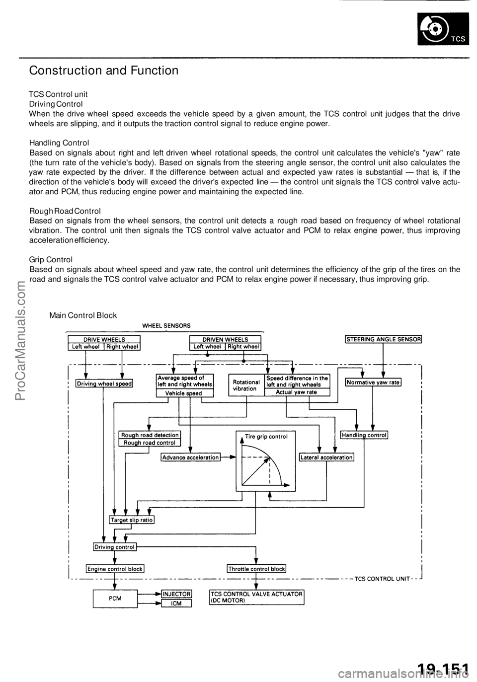
TCS Control unit
Driving Control
When the drive wheel speed exceeds the vehicle speed by a given amount, the TCS control unit judges that the drive
wheels are slipping, and it outputs the traction control signal to reduce engine power.
Handling Control
Based on signals about right and left driven wheel rotational speeds, the control unit calculates the vehicle's "yaw" rate
(the turn rate of the vehicle's body). Based on signals from the steering angle sensor, the control unit also calculates the
yaw rate expected by the driver. If the difference between actual and expected yaw rates is substantial — that is, if the
direction of the vehicle's body will exceed the driver's expected line — the control unit signals the TCS control valve actu-
ator and PCM, thus reducing engine power and maintaining the expected line.
Rough Road Control
Based on signals from the wheel sensors, the control unit detects a rough road based on frequency of wheel rotational
vibration. The control unit then signals the TCS control valve actuator and PCM to relax engine power, thus improving
acceleration efficiency.
Grip Control
Based on signals about wheel speed and yaw rate, the control unit determines the efficiency of the grip of the tires on the
road and signals the TCS control valve actuator and PCM to relax engine power if necessary, thus improving grip.
Main Control BlockProCarManuals.com
Page 1194 of 1954
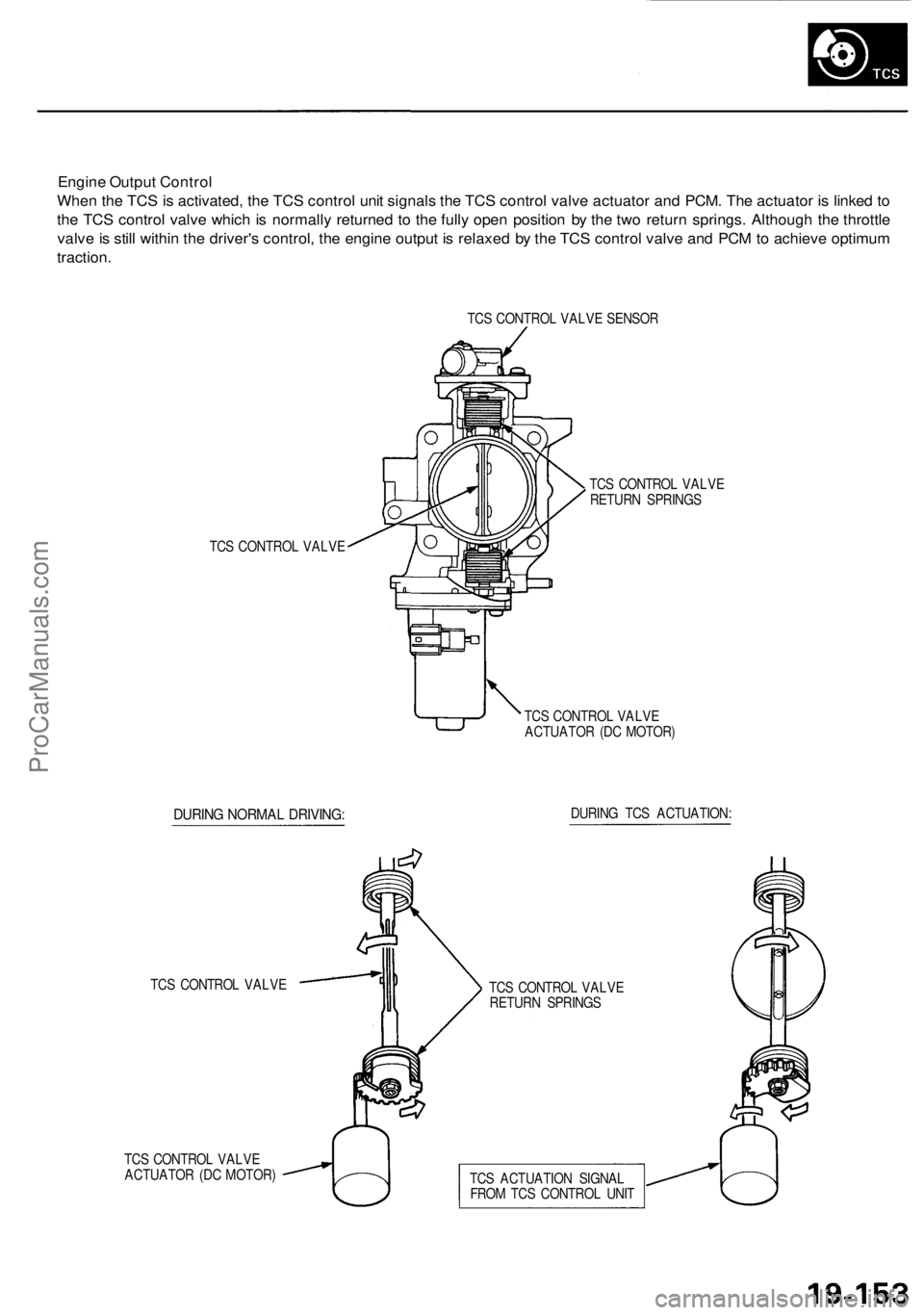
Engine Output Control
When the TCS is activated, the TCS control unit signals the TCS control valve actuator and PCM. The actuator is linked to
the TCS control valve which is normally returned to the fully open position by the two return springs. Although the throttle
valve is still within the driver's control, the engine output is relaxed by the TCS control valve and PCM to achieve optimum
traction.
TCS CONTROL VALVE SENSOR
TCS CONTROL VALVE
TCS CONTROL VALVE
RETURN SPRINGS
TCS CONTROL VALVE
ACTUATOR (DC MOTOR)
DURING NORMAL DRIVING:
DURING TCS ACTUATION:
TCS CONTROL VALVE
TCS CONTROL VALVE
ACTUATOR (DC MOTOR)
TCS CONTROL VALVE
RETURN SPRINGS
TCS ACTUATION SIGNAL
FROM TCS CONTROL UNITProCarManuals.com
Page 1196 of 1954
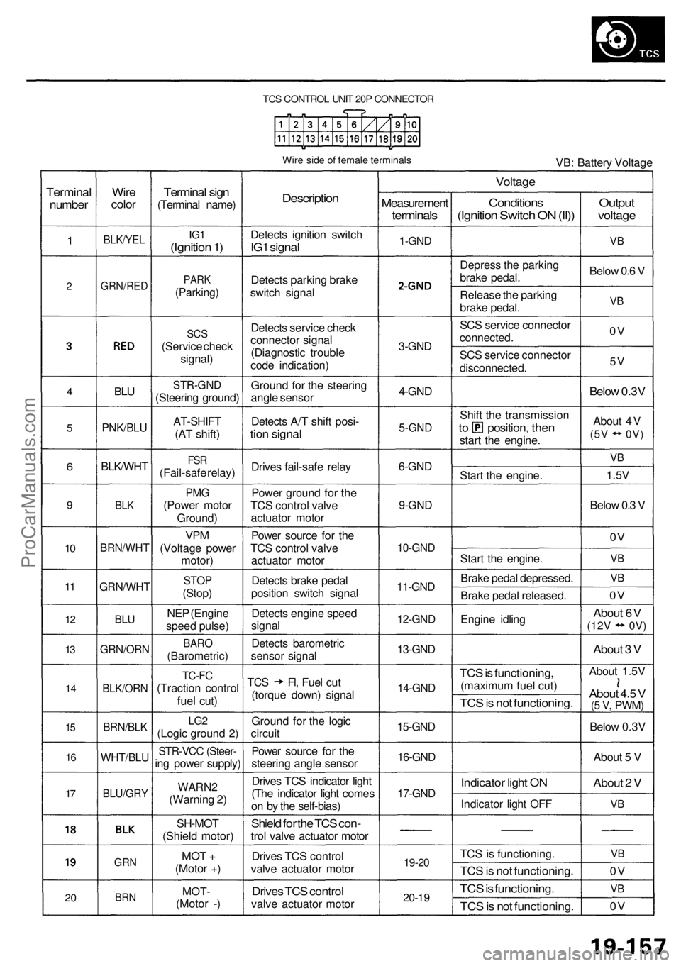
TCS CONTROL UNIT 20P CONNECTOR
Wire side of female terminals
VB: Battery Voltage
Terminal
number
1
2
4
5
6
9
10
11
12
13
14
15
16
17
20
Wire
color
BLK/YEL
GRN/RED
BLU
PNK/BLU
BLK/WHT
BLK
BRN/WHT
GRN/WHT
BLU
GRN/ORN
BLK/ORN
BRN/BLK
WHT/BLU
BLU/GRY
GRN
BRN
Terminal sign
(Terminal name)
IG1
(Ignition 1)
PARK
(Parking)
SCS
(Service check
signal)
STR-GND
(Steering ground)
AT-SHIFT
(AT shift)
FSR
(Fail-safe relay)
PMG
(Power motor
Ground)
VPM
(Voltage power
motor)
STOP
(Stop)
NEP (Engine
speed pulse)
BARO
(Barometric)
TC-FC
(Traction control
fuel cut)
LG2
(Logic ground 2)
STR-VCC (Steer-
ing power supply)
WARN2
(Warning 2)
SH-MOT
(Shield motor)
MOT +
(Motor +)
MOT-
(Motor -)
Description
Detects ignition switch
IG1 signal
Detects parking brake
switch signal
Detects service check
connector signal
(Diagnostic trouble
code indication)
Ground for the steering
angle sensor
Detects A/T shift posi-
tion signal
Drives fail-safe relay
Power ground for the
TCS control valve
actuator motor
Power source for the
TCS control valve
actuator motor
Detects brake pedal
position switch signal
Detects engine speed
signal
Detects barometric
sensor signal
TCS Fl, Fuel cut
(torque down) signal
Ground for the logic
circuit
Power source for the
steering angle sensor
Drives TCS indicator light
(The indicator light comes
on by the self-bias)
Shield for the TCS con-
trol valve actuator motor
Drives TCS control
valve actuator motor
Drives TCS control
valve actuator motor
Measurement
terminals
1-GND
2
3-GND
4-GND
5-GND
6-GND
9-GND
10-GND
11-GND
12-GND
13-GND
14-GND
15-GND
16-GND
17-GND
19-20
20-19
Voltage
Conditions
(Ignition Switch ON (II))
Depress the parking
brake pedal.
Release the parking
brake pedal.
SCS service connector
connected.
SCS service connector
disconnected.
Shift the transmission
to position, then
start the engine.
Start the engine.
Start the engine.
Brake pedal depressed.
Brake pedal released.
Engine idling
TCS is functioning,
(maximum fuel cut)
TCS is not functioning.
Indicator light ON
Indicator light OFF
TCS is functioning.
TCS is not functioning.
TCS is functioning.
TCS is not functioning.
Output
voltage
VB
Below 0.6 V
VB
0V
5V
Below 0.3V
About 4V
(5V 0V)
VB
1.5V
Below 0.3 V
0V
VB
VB
0V
About 6V
(12V
0V)
About 3 V
About 1.5V
About 4.5 V
(5 V,
PWM)
Below 0.3V
About 5 V
About 2 V
VB
VB
0V
VB
0VProCarManuals.com
Page 1198 of 1954
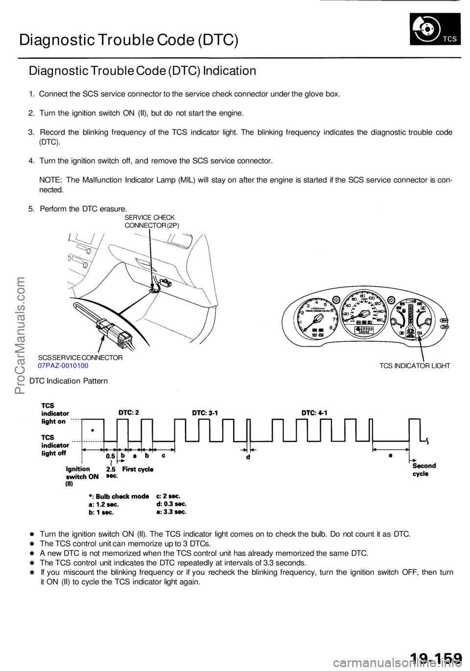
Diagnostic Troubl e Cod e (DTC )
Diagnosti c Troubl e Cod e (DTC ) Indicatio n
1. Connec t th e SC S servic e connecto r t o th e servic e chec k connecto r unde r th e glov e box .
2 . Tur n th e ignitio n switc h O N (II) , bu t d o no t star t th e engine .
3 . Recor d th e blinkin g frequenc y o f th e TC S indicato r light . Th e blinkin g frequenc y indicate s th e diagnosti c troubl e cod e
(DTC) .
4. Tur n th e ignitio n switc h off , an d remov e th e SC S servic e connector .
NOTE : Th e Malfunctio n Indicato r Lam p (MIL ) wil l sta y o n afte r th e engin e is starte d if th e SC S servic e connecto r i s con -
nected .
5 . Perfor m th e DT C erasure .
SERVIC E CHEC KCONNECTO R (2P )
SC S SERVIC E CONNECTO R
07PAZ-001010 0
DTC Indicatio n Patter n
TCS INDICATO R LIGH T
Turn th e ignitio n switc h O N (II) . Th e TC S indicato r ligh t come s o n to chec k th e bulb . D o no t coun t i t a s DTC .
Th e TC S contro l uni t ca n memoriz e u p to 3 DTCs .
A ne w DT C is no t memorize d whe n th e TC S contro l uni t ha s alread y memorize d th e sam e DTC .
Th e TC S contro l uni t indicate s th e DT C repeatedl y a t interval s o f 3. 3 seconds .
I f yo u miscoun t th e blinkin g frequenc y o r i f yo u rechec k th e blinkin g frequency , tur n th e ignitio n switc h OFF , the n tur n
i t O N (II ) t o cycl e th e TC S indicato r ligh t again .
ProCarManuals.com
Page 1209 of 1954
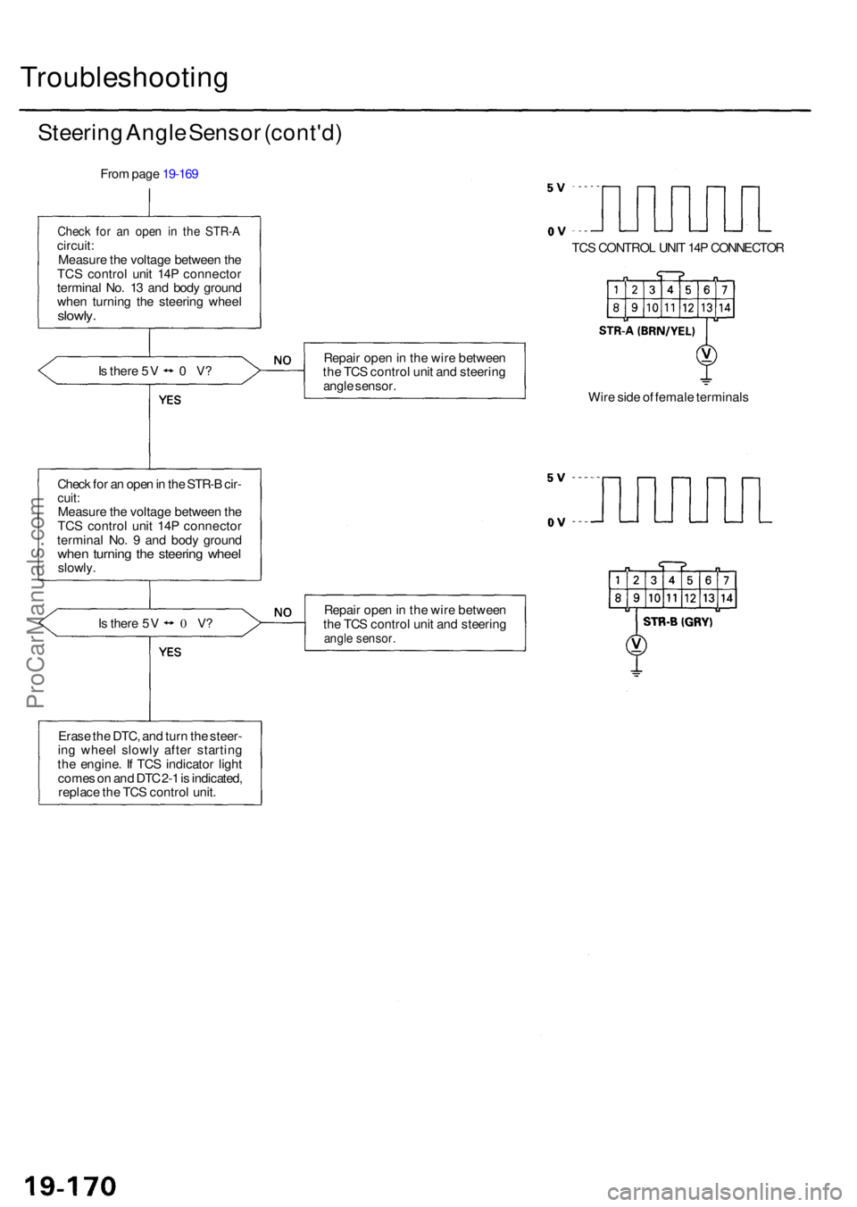
Troubleshooting
Steering Angl e Senso r (cont'd )
From pag e 19-16 9
Chec k fo r a n ope n i n th e STR- Acircuit:Measur e th e voltag e betwee n th e
TC S contro l uni t 14 P connecto r
termina l No . 1 3 an d bod y groun d
whe n turnin g th e steerin g whee l
slowly.
Is ther e 5 V 0 V?
Chec k fo r a n ope n in th e STR- B cir -
cuit :Measur e th e voltag e betwee n th e
TC S contro l uni t 14 P connecto r
termina l No . 9 an d bod y groun d
when turnin g th e steerin g whee lslowly .
Is ther e 5 V 0 V? Repai
r ope n in th e wir e betwee n
th e TC S contro l uni t an d steerin g
angl e sensor .
Wire sid e o f femal e terminal s
Repai r ope n in th e wir e betwee n
th e TC S contro l uni t an d steerin gangle sensor .
Erase th e DTC , an d tur n th e steer -
in g whee l slowl y afte r startin g
th e engine . I f TC S indicato r ligh t
come s o n an d DT C 2- 1 is indicated ,
replac e th e TC S contro l unit . TC
S CONTRO L UNI T 14 P CONNECTO R
ProCarManuals.com
Page 1211 of 1954
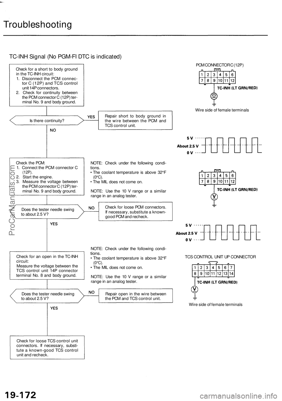
Troubleshooting
TC-INH Signal (No PGM-FI DTC is indicated)
Check for a short to body ground
in the TC-INH circuit:
1. Disconnect the PCM connec-
tor C (12P) and TCS control
unit 14P connectors.
2. Check for continuity between
the PCM connector C (12P) ter-
minal No. 9 and body ground.
Is there continuity?
Check the PCM:
1. Connect the PCM connector C
(12P).
2. Start the engine.
3. Measure the voltage between
the PCM connector C (12P) ter-
minal No. 9 and body ground.
Does the tester needle swing
to about 2.5 V?
Check for an open in the TC-INH
circuit:
Measure the voltage between the
TCS control unit 14P connector
terminal No. 8 and body ground.
Does the tester needle swing
to about 2.5 V?
Check for loose TCS control unit
connectors. If necessary, substi-
tute a known-good TCS control
unit and recheck.
PCM CONNECTOR C (12P)
Repair short to body ground in
the wire between the PCM and
TCS control unit.
Wire side of female terminals
NOTE: Check under the following condi-
tions.
The coolant temperature is above 32°F
(0°C).
The MIL does not come on.
NOTE: Use the 10 V range or a similar
range in an analog tester.
Check for loose PCM connectors.
If necessary, substitute a known-
good PCM and recheck.
NOTE: Check under the following condi-
tions.
The coolant temperature is above 32°F
(0°C).
The MIL does not come on.
NOTE: Use the 10 V range or a similar
range in an analog tester.
TCS CONTROL UNIT UP CONNECTOR
Repair open in the wire between
the PCM and TCS control unit.
Wire side of female terminalsProCarManuals.com
Page 1212 of 1954
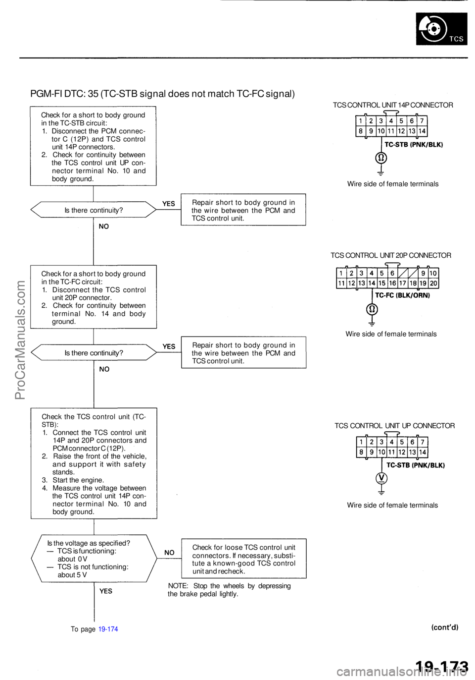
PGM-FI DTC : 3 5 (TC-ST B signa l doe s no t matc h TC-F C signal )
Check fo r a shor t t o bod y groun d
i n th e TC-ST B circuit :
1 . Disconnec t th e PC M connec -
to r C (12P ) an d TC S contro l
uni t 14 P connectors .
2 . Chec k fo r continuit y betwee n
th e TC S contro l uni t U P con -
necto r termina l No . 1 0 an d
bod y ground . TC
S CONTRO L UNI T 14 P CONNECTO R
Wir e sid e o f femal e terminal s
I s ther e continuity ? Repai
r shor t t o bod y groun d in
th e wir e betwee n th e PC M an d
TC S contro l unit .
TCS CONTRO L UNI T 20 P CONNECTO R
Chec k fo r a shor t t o bod y groun d
i n th e TC-F C circuit :
1 . Disconnec t th e TC S contro l
uni t 20 P connector .
2 . Chec k fo r continuit y betwee n
termina l No . 1 4 an d bod y
ground .
Is ther e continuity ?Repair shor t t o bod y groun d in
th e wir e betwee n th e PC M an d
TC S contro l unit . Wir
e sid e o f femal e terminal s
Chec k th e TC S contro l uni t (TC -
STB) :1. Connec t th e TC S contro l uni t
14 P an d 20 P connector s an d
PC M connecto r C (12P) .
2 . Rais e th e fron t o f th e vehicle ,
and suppor t i t wit h safet ystands.
3 . Star t th e engine .
4 . Measur e th e voltag e betwee n
th e TC S contro l uni t 14 P con -
necto r termina l No . 1 0 an d
bod y ground . TC
S CONTRO L UNI T U P CONNECTO R
Wir e sid e o f femal e terminal s
I s th e voltag e a s specified ?
TCS is functioning :about 0 V
TC S is no t functioning :
abou t 5 V Chec
k fo r loos e TC S contro l uni t
connectors . I f necessary , substi -
tut e a known-goo d TC S contro l
uni t an d recheck .
To pag e 19-17 4
NOTE : Sto p th e wheel s b y depressin g
th e brak e peda l lightly .
ProCarManuals.com