Page 826 of 1954
26. Remove the transmission housing mounting bolts.
TRANSMISSION HOUSING
MOUNTING BOLT
TRANSMISSION
HOUSING MOUNTING
BOLTS
27. Remove the engine stiffener.
TRANSMISSION HOUSING
MOUNTING BOLT
DRIVE PLATE
BOLT
ENGINE
STIFFENER
26 mm SHIM
TORQUE CONVERTER
COVERS
28. Remove the torque converter covers.
29. Remove the six drive plate bolts one at a time while
rotating the crankshaft pulley.
NOTE: If necessary, remove the spark plugs while
removing the drive plate bolts.
30. Remove the transmission housing mounting bolts.
31. Pull the transmission away from the engine until it
clears the dowel pins, then lower it on the transmis-
sion jack.ProCarManuals.com
Page 898 of 1954

Transmission
Installation
1. Flus h th e AT F coole r (se e page s 14-19 5 an d 14-196 ).
2 . Instal l th e torqu e converte r securel y wit h a ne w O-rin g
o n th e mainshaft , an d instal l tw o 1 4 x 2 0 m m dowe l
pin s in th e torqu e converte r housing .
14 x 20 m mDOWE L PI N
O-RIN G
Replace .
14 x 20 m mDOWE L PI NEXTENSIO NSHAFT
TORQUE
CONVERTE R
3. Clea n th e extensio n shaf t openin g o n th e differen -
tia l side .
4 . Inser t th e extensio n shaf t i n it s opening , an d appl y
Supe r Hig h Tem p Ure a Greas e (P/ N 0879 8 - 9002 ) t o
th e shaf t splines .
EXTENSIO N SHAF T
5. Plac e th e transmissio n o n a jack , an d rais e i t t o
engin e level . 6
. Attac h th e transmissio n t o th e engine , the n instal l
th e transmissio n housin g mountin g bol t wit h th e
2 6 m m shim .
NOTE : D o no t instal l th e transmissio n housin g bol t
o n th e engin e stiffene r side .
8 x 1.2 5 mm22 N- m (2. 2 kgf-m , 1 6 Ibf-ft )
ENGIN ESTIFFENE R
12 x 1.2 5 mm64 N- m (6. 5 kgf-m ,
4 7 Ibf-ft )8 x 1.2 5 mm22 N- m(2.2 kgf-m ,
1 6 Ibf-ft )
26 m m SHI M
6 x 1. 0 m m12 N- m (1. 2 kgf-m ,
8. 7 Ibf-ft )
TRANSMISSIO N HOUSIN GMOUNTIN G BOL T12 x 1.2 5 mm64 N- m (6. 5 kgf-m , 4 7 Ibf-ft )
TORQU E CONVERTE R
COVER S
7. Attac h th e torqu e converte r t o th e driv e plat e wit h
si x bolt s an d torque :
Rotat e th e crankshaf t a s necessar y t o tighte n th e
bolt s t o 1/ 2 o f th e specifie d torque , the n t o th e fina l
torque , i n a crisscros s pattern . Afte r tightenin g th e
las t bolt , chec k tha t th e crankshaf t rotate s freely .
8 . Instal l th e torqu e converte r covers .
9 . Instal l th e engin e stiffener . Tighte n th e engin e stiff -
ene r 8 m m bolt s loosely , an d tighte n th e transmis -
sio n housin g mountin g bol t t o th e specifie d torque ,
the n tighte n th e 8 m m bolt s t o th e specifie d torque .
SUPER HIG H TEM P
URE A GREAS E
(P/N 0879 8 -9002 )
ProCarManuals.com
Page 903 of 1954

Transmission
Installation (cont'd )
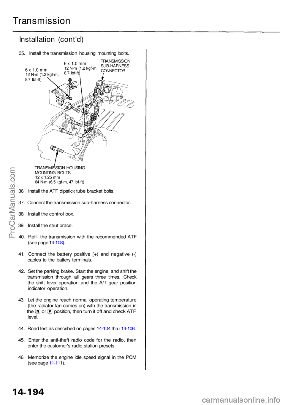
TRANSMISSIO N HOUSIN GMOUNTIN G BOLT S12 x 1.2 5 m m64 N- m (6. 5 kgf-m , 4 7 Ibf-ft )
36. Instal l th e AT F dipstic k tub e bracke t bolts .
37 . Connec t th e transmissio n sub-harnes s connector .
38 . Instal l th e contro l box .
39 . Instal l th e stru t brace .
40 . Refil l th e transmissio n wit h th e recommende d AT F
(se e pag e 1 4-108 ).
41 . Connec t th e batter y positiv e (+ ) an d negativ e (- )
cable s t o th e batter y terminals .
42 . Se t th e parkin g brake . Star t th e engine , an d shif t th e
transmissio n throug h al l gear s thre e times . Chec k
th e shif t leve r operatio n an d th e A/ T gea r positio n
indicato r operation .
43 . Le t th e engin e reac h norma l operatin g temperatur e
(th e radiato r fa n come s on ) wit h th e transmissio n in
th e o r position , the n tur n it of f an d chec k AT F
level .
44 . Roa d tes t a s describe d o n page s 14-10 4 thr u 14-106 .
45 . Ente r th e anti-thef t radi o cod e fo r th e radio , the n
ente r th e customer' s radi o statio n presets .
46 . Memoriz e th e engin e idl e spee d signa l i n th e PC M
(se e pag e 11-111 ).
35
. Instal l th e transmissio n housin g mountin g bolts .
TRANSMISSIO NSUB-HARNES SCONNECTOR
6 x 1. 0 m m12 N- m (1. 2 kgf-m ,8.7 Ibf-ft )6 x 1. 0 m m12 N- m (1. 2 kgf-m ,8.7 Ibf-ft )
ProCarManuals.com
Page 909 of 1954

Link Adjustmen t
• Mak e sur e lifts , jack s an d safet y stand s ar e place d
properl y (se e sectio n 1 ).
• Appl y parkin g
brake, and bloc k rea r wheel s s o vehi -
cle wil l no t rol l of f stand s an d fal l o n yo u whil e work -
ing unde r it .
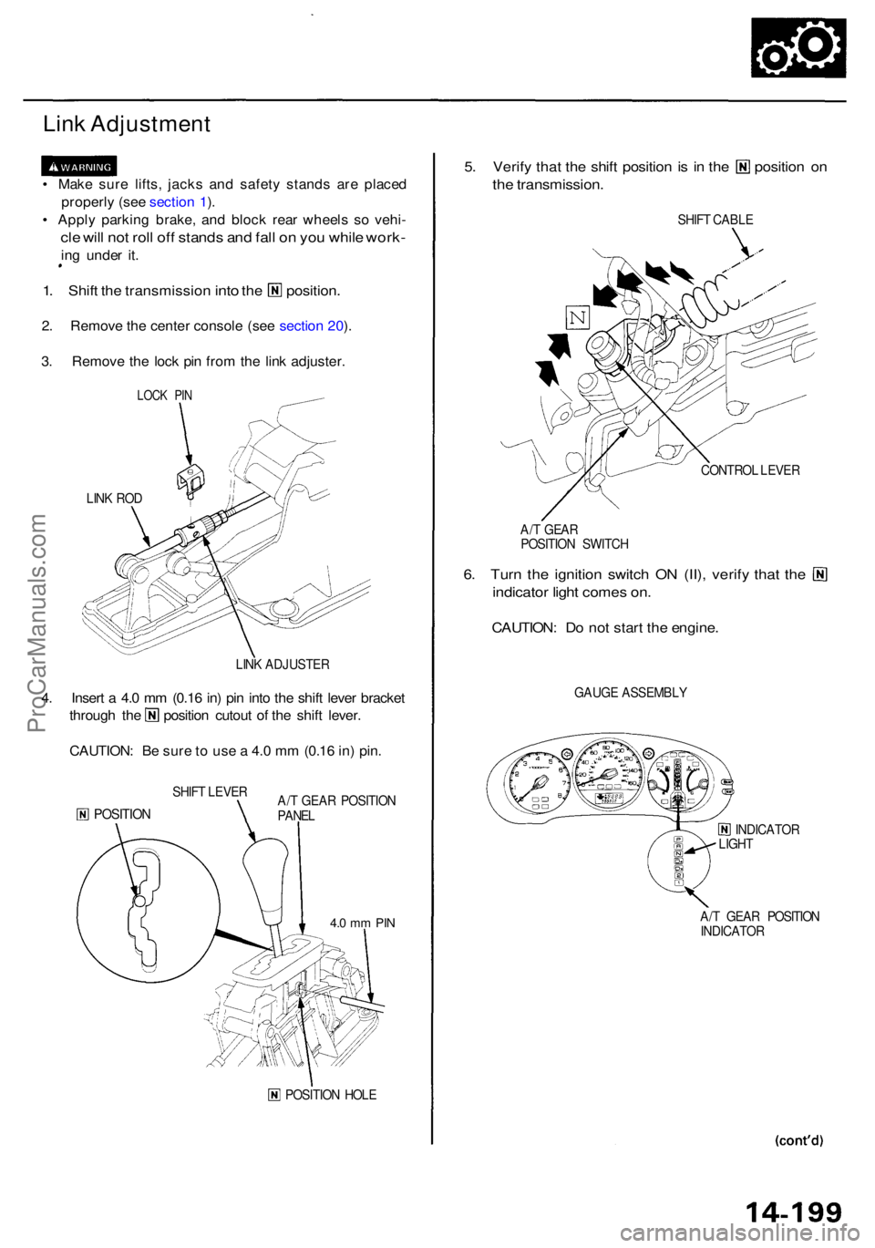
1. Shif t the transmissio n into the position .
2. Remov e th e cente r consol e (se e sectio n 20 ).
3 . Remov e th e loc k pi n fro m th e lin k adjuster .
LINK RO D
LINK ADJUSTE R
4. Inser t a 4. 0 m m (0.1 6 in ) pi n int o th e shif t leve r bracke t
through th e positio n cutou t o f th e shif t lever .
CAUTION : B e sur e t o us e a 4. 0 m m (0.1 6 in ) pin .
SHIF T LEVE R
POSITIO NA/T GEA R POSITIO N
PANE L
POSITIO N HOL E
5. Verif y tha t th e shif t positio n is i n th e positio n o n
the transmission .
SHIFT CABL E
CONTRO L LEVE R
A/ T GEA R
POSITIO N SWITC H
6. Tur n th e ignitio n switc h O N (II) , verif y tha t th e
indicato r ligh t come s on .
CAUTION : D o no t star t th e engine .
GAUGE ASSEMBL Y
INDICATOR
LIGH T
A/ T GEA R POSITIO N
INDICATO R
LOCK PI N
4.0 m m PI N
ProCarManuals.com
Page 910 of 1954

Shift Leve r
Link Adjustmen t (cont'd)
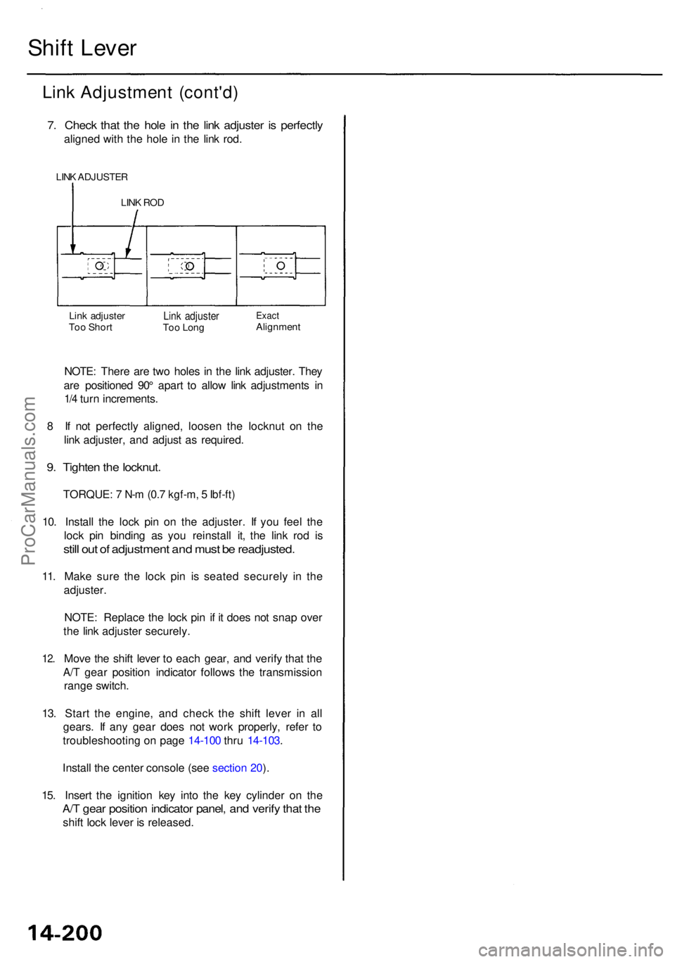
7. Chec k tha t th e hol e i n th e lin k adjuste r i s perfectl y
aligned wit h th e hol e i n th e lin k rod .
LINK ADJUSTE R
Lin k adjuste r
Too Shor tLink adjuste rToo Lon gExac tAlignmen t
NOTE: Ther e ar e tw o hole s i n th e lin k adjuster . The y
ar e positione d 90 ° apar t t o allo w lin k adjustment s i n
1/ 4 tur n increments .
8 I f no t perfectl y aligned , loose n th e locknu t o n th e
lin k adjuster , an d adjus t a s required .
9. Tighte n th e locknut .
TORQUE : 7 N- m (0. 7 kgf-m , 5 Ibf-ft)
10. Instal l th e loc k pi n o n th e adjuster . I f yo u fee l th e
loc k pi n bindin g a s yo u reinstal l it , th e lin k ro d i s
stil l ou t o f adjustmen t an d mus t b e readjusted .
11. Mak e sur e th e loc k pi n i s seate d securel y i n th e
adjuster .
NOTE : Replac e th e loc k pi n i f i t doe s no t sna p ove r
th e lin k adjuste r securely .
12. Mov e th e shif t leve r t o eac h gear , an d verif y tha t th e
A/T gea r positio n indicato r follow s th e transmissio n
rang e switch .
13 . Star t th e engine , an d chec k th e shif t leve r i n al l
gears . I f an y gea r doe s no t wor k properly , refe r t o
troubleshootin g o n pag e 14-10 0 thru 14-103 .
14. Instal l th e cente r consol e (se e sectio n 20 ).
15 . Inser t th e ignitio n ke y int o th e ke y cylinde r o n th e
A/T gea r positio n indicato r panel , an d verif y tha t th e
shif t loc k leve r i s released .
LINK RO D
ProCarManuals.com
Page 915 of 1954

Maintenance
Differential Oil
NOTE: Check the differential oil with engine OFF, and
the vehicle on level ground.
1. Remove the oil filler plug, then check the level and
condition of the oil.
WASHER
Replace.
Proper Lever
OIL FILLER PLUG
44 N-m (4.5 kgf-m, 33 Ibf-ft)
WASHER Replace.
2. The oil level must be up to the fill hole. If it is below
the hole, add oil until it runs out, then reinstall the
oil filler plug with a new washer.
3. If the differential oil is dirty, remove the drain plug,
and drain the oil.
DRAIN PLUG
39 N-m (4.0 kgf-m, 29 Ibf-ft)
WASHER Replace.
OIL FILLER PLUG
44 N-m (4.5 kgf-m, 33 Ibf-ft)
4. Reinstall the drain plug with a new washer, and refill
the differential with the recommended oil to the
proper level.
NOTE:
The drain plug washer should be replaced at every
oil change.
Clean the drain plug before reinstalling.
5. Reinstall the oil filler plug with a new washer.
Oil Capacity
1.05 (1.11 US qt, 0.92 Imp qt) at oil change
1.10 (1.16 US qt, 0.97 Imp qt) at overhaul
Recommended oil:
Hypoid gear oil
API Classification GL4 or GL5
viscosity:
SAE 90 above 0°F (-18°C)
SAE 80 W - 90 below 0°F (-18°C)ProCarManuals.com
Page 916 of 1954

Differential Assembly
Removal
Make sur e jack s an d safet y stand s ar e place d properly ,
an d hois t bracket s ar e attache d to correc t position s o n
th e engine .
Appl y parkin g brak e an d bloc k rea r wheel s s o th e
vehicl e wil l no t rol l of f stand s an d fal l o n yo u whil e
workin g unde r it .
CAUTION : Us e fende r cover s to avoi d damagin g painte d
surfaces .
1. Remov e th e drai n plug , an d drai n th e differentia l oi l
(se e pag e 15-4 ).
2 . Remov e th e cotte r pin s an d castl e nuts , tha n sepa -
rat e th e bal l joint s fro m th e lowe r ar m usin g th e
specia l too l (se e sectio n 18 ).
3 . Remov e th e righ t dampe r pinc h bolt , the n separat e
th e dampe r for k an d dampe r (se e sectio n 18 ).
4 . Pr y th e driveshaft s ou t o f th e differentia l an d inter -
mediat e shaf t (se e sectio n 16 ).
CAUTION :
D o no t pul l o n th e driveshaft , a s th e inboar d
join t ma y com e apart .
Us e car e whe n pryin g ou t th e assembly , an d pul l
i t straigh t t o avoi d damagin g th e differentia l oi l
sea l o r th e intermediat e shaf t oute r seal .
5 . Pul l o n th e inboar d join t t o remov e th e righ t drive -
shaf t fro m th e differentia l an d t o remov e th e lef t
driveshaft from the intermediate shaft (see
section 16 ).
6 . Remov e th e intermediat e shaf t assembl y fro m th e
oi l pa n (se e sectio n 16 ).
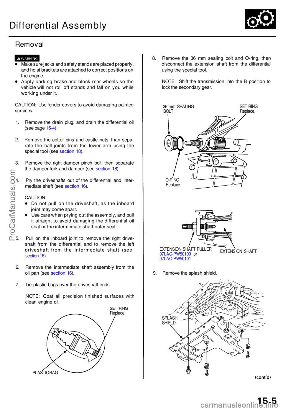
7 . Ti e plasti c bag s ove r th e driveshaf t ends .
NOTE : Coa t al l precisio n finishe d surface s wit h
clea n engin e oil .
SE T RIN GReplace .
PLASTIC BA G
8. Remov e th e 3 6 m m sealin g bol t an d O-ring , the n
disconnec t th e extensio n shaf t fro m th e differentia l
usin g th e specia l tool .
NOTE : Shif t th e transmissio n int o th e B positio n t o
loc k th e secondar y gear .
36 m m SEALIN GBOLTSET RIN GReplace .
O-RINGReplace .
EXTENSIO N SHAF T PULLE R
07LAC-PW5010 0 o r
07LAC-PW5010 1 EXTENSIO
N SHAF T
9. Remov e th e splas h shield .
SPLAS HSHIELD
ProCarManuals.com
Page 918 of 1954
14. Disconnec t th e breathe r tub e fro m th e clamp , the n
remov e th e righ t exhaus t manifol d cover .
CLAMP
BREATHE RTUBE
RIGH T EXHAUS TMANIFOLD COVE R
15. Remov e th e engin e sto p moun t bracke t bolts .
ENGIN E STO PMOUNT S
ENGINE STO PMOUN T BRACKE T BOLT S
16. Attac h th e chai n hois t t o th e engin e (se e sectio n 5 ).
17 . Remov e th e righ t an d lef t engin e moun t bracke t
nuts , the n remov e th e righ t engin e moun t bracket .
ENGINE MOUN TBRACKE T NU T
RIGH T ENGIN EMOUNT BRACKE T
18. Remov e th e righ t engin e mount .
RIGHT ENGIN EMOUNT
ProCarManuals.com