1996 ACURA RL KA9 engine
[x] Cancel search: enginePage 623 of 1954

Idle Contro l Syste m
Idle Spee d Settin g
Inspection/Adjustmen t
NOTE:
• Befor e settin g th e idl e speed , chec k th e followin g
items:
— Th e MI L ha s no t bee n reporte d on .
— Ignitio n timin g
— Spar k plug s
— Ai r cleane r
— PC V syste m
• (Canada ) Depres s th e parkin g brak e pedal . Star t th e
engine , the n chec k tha t th e headlight s ar e off .
1 . Connec t a OBDI I sca n too l (se e pag e 11-40 ) o r
tachometer .
• Connec t a tachomete r t o ignite r uni t secondar y
loo p (white-taped) .
• Remov e th e rubbe r ca p fro m th e tachomete r
connecto r an d connec t a tachometer .
TACHOMETE RCONNECTORTACHOMETE R
RUBBERCAP
BATTER Y
2. Star t th e engine . Hol d th e engin e a t 3,00 0 rp m wit h
n o loa d (i n Par k o r neutral ) unti l th e radiato r fa n
come s on , the n le t i t idle . 3
. Disconnec t th e IA C valv e connector .
IAC VALV E
4. I f th e engin e stalls , star t th e engin e wit h th e acceler -
ato r peda l slightl y depressed . Stabiliz e th e rp m a t
1,000 , the n slowl y releas e th e peda l unti l th e engin e
idles .
5 . Chec k idlin g unde r th e followin g conditions : head -
light s (Hi ) an d rea r defogge r on , blowe r fan , radia -
to r fan , an d ai r conditione r ar e no t operating .
Idl e spee d shoul d be :
480 5 0 rp m
(in Par k o r neutral )
Adjust th e idl e speed , i f necessary , b y turnin g th e
idl e adjustin g screw .
NOTE : Afte r adjustin g th e idl e spee d i n thi s step ,
rechec k th e ignitio n timin g (se e sectio n 4 ).
I f i t i s ou t o f spec , g o bac k t o ste p 4 .
IDL E ADJUSTIN G SCRE W
TACHOMETE
R
ProCarManuals.com
Page 624 of 1954

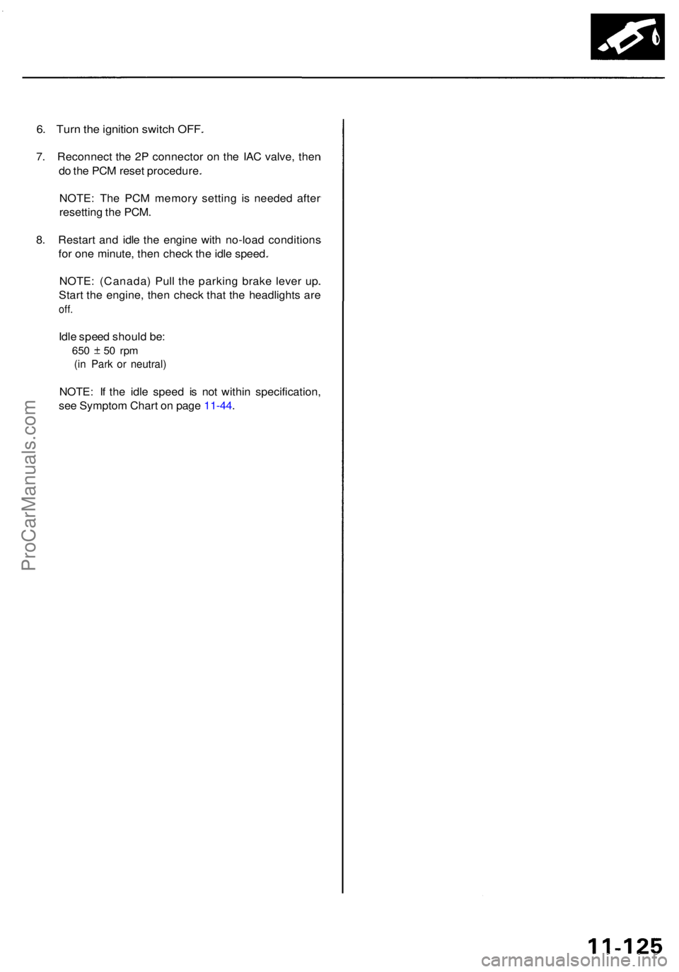
6. Tur n th e ignitio n switc h OFF .
7. Reconnec t th e 2 P connecto r o n th e IA C valve , the n
d o th e PC M rese t procedure .
NOTE : Th e PC M memor y settin g i s neede d afte r
resettin g th e PCM .
8 . Restar t an d idl e th e engin e wit h no-loa d condition s
fo r on e minute , the n chec k th e idl e speed .
NOTE : (Canada ) Pul l th e parkin g brak e leve r up .
Star t th e engine , the n chec k tha t th e headlight s ar e
off.
Idle spee d shoul d be :
650 5 0 rp m
(in Par k o r neutral )
NOTE: I f th e idl e spee d i s no t withi n specification ,
se e Sympto m Char t o n pag e 11-44 .
ProCarManuals.com
Page 625 of 1954

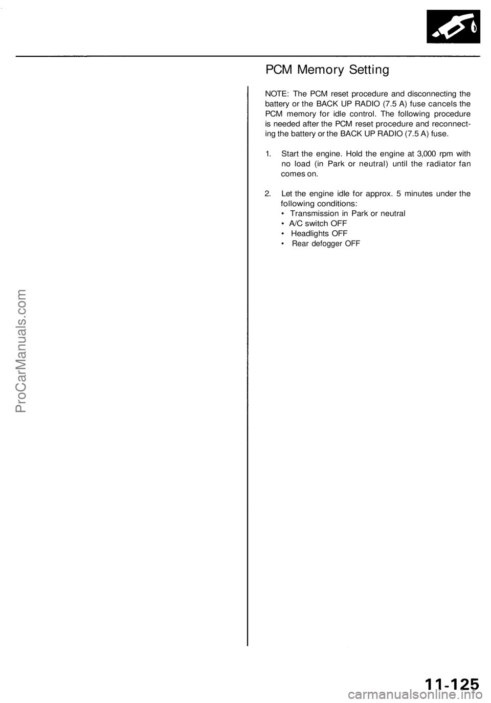
PCM Memory Setting
NOTE: The PCM reset procedure and disconnecting the
battery or the BACK UP RADIO (7.5 A) fuse cancels the
PCM memory for idle control. The following procedure
is needed after the PCM reset procedure and reconnect-
ing the battery or the BACK UP RADIO (7.5 A) fuse.
1. Start the engine. Hold the engine at 3,000 rpm with
no load (in Park or neutral) until the radiator fan
comes on.
2. Let the engine idle for approx. 5 minutes under the
following conditions:
• Transmission in Park or neutral
• A/C switch OFF
• Headlights OFF
• Rear defogger OFFProCarManuals.com
Page 632 of 1954

Fuel Suppl y Syste m
System Descriptio n
The fue l suppl y syste m consist s o f a fue l tank , in-tan k
high-pressur e fue l pump , PGM-F I mai n relay , fue l filter ,
fue l pressur e regulator , fue l pressur e regulato r contro l
solenoi d valve , injectors , an d fue l deliver y an d retur n
lines . Thi s syste m deliver s pressure-regulate d fue l t o th e
injector s an d cut s th e fue l deliver y whe n th e engin e i s
no t running .
Fuel Pressur e
Relieving
Befor e disconnectin g fue l pipe s o r hoses , releas e pres -
sur e fro m th e syste m b y loosenin g th e servic e bol t o n
top o f th e fue l filter .
SERVIC E
BOL T
12 N- m(1.2 kgf-m , 8. 7 Ibf-ft )
FUE L
FILTE R
SHOP TOWE L
NOTE:
• A fue l pressur e gaug e can be attache d a t th e ser -
vic e bol t hole .
• Alway s replac e th e washe r betwee n th e servic e
bol t an d th e specia l banj o bol t wheneve r th e ser -
vic e bol t i s loosened .
• Replac e al l washer s wheneve r th e bolt s ar e
removed . Inspectio
n
1 . Reliev e fue l pressure .
2 . Remov e th e servic e bol t o n th e fue l filte r whil e hold -
in g th e banj o bol t wit h anothe r wrench . Attac h th e
specia l tool .
FUEL FILTE R
3. Star t th e engine . Measur e th e fue l pressur e wit h th e
engin e idlin g an d th e vacuu m hos e o f th e fue l pres -
sur e regulato r disconnecte d fro m th e fue l pressur e
regulato r an d pinched . I f th e engin e wil l no t start ,
turn th e ignitio n switc h O N (II) , wai t fo r tw o sec -
onds , tur n i t OFF , the n bac k o n agai n an d rea d th e
fue l pressure .
Pressur e shoul d be :
29 9 - 34 8 kP a (3.0 5 - 3.5 5 kgf/cm
2, 43. 4 - 50. 5 psi )
4 . Reconnec t vacuu m hos e to th e fue l pressur e regula -
tor.
Pressur e shoul d be :
24 0 - 28 9 kP a (2.4 5 - 2.9 5 kgf/cm2, 34. 8 - 41. 9 psi )
I f th e fue l pressur e i s no t a s specified , firs t chec k th e
fue l pum p (se e pag e 11-142 ). I f th e fue l pum p is OK ,
chec k th e following :
• I f th e fue l pressur e i s highe r tha n specified ,
inspec t for :
— Pinche d o r clogge d fue l retur n hos e o r line .
— Fault y fue l pressur e regulato r (se e pag e
11-135 ).
• I f th e fue l pressur e i s lowe r tha n specified , inspec t
for:
— Clogge d fue l filter .
— Fault y fue l pressur e regulato r (se e pag e
11-135 ).
— Fue l lin e leakage .
1
. Mak e sur e yo u hav e th e anti-thef t cod e fo r th e
radio , the n writ e dow n th e frequencie s fo r th e
radio' s prese t buttons .
2 . Disconnec t th e batter y negativ e cabl e fro m th e bat -
ter y negativ e terminal .
3. Remov e th e fue l fil l cap .
4. Us e a bo x en d wrenc h o n th e servic e bol t a t th e fue l
filte r whil e holdin g th e specia l banj o bol t wit h
anothe r wrench .
5. Plac e a ra g o r sho p towe l ove r th e servic e bolt .
6 . Slowl y loose n th e servic e bol t on e complet e turn .
7 . Reconnec t th e battery , ente r th e anti-thef t cod e fo r
th e radio , the n ente r th e customer' s radi o statio n
presets .
•
D o no t smok e whil e workin g o n th e fue l system .
Kee p ope n flame s o r spark s awa y fro m you r wor k area .
• B e sur e t o reliev e fue l pressur e whil e th e ignitio n
switch is off .
CLAM P
FUE
L
PRESSUR E
REGULATO R FUE
L
PRESSUR E
GAUG E
07406-004000 1
ProCarManuals.com
Page 634 of 1954

Fuel Supply System
Injectors (cont'd)
13. Slide new cushion rings onto the injectors.
14. Coat new O-rings with clean engine oil, and put them on the injectors.
15. Insert the injectors into the fuel rail first.
16. Coat new seal rings with clean engine oil and press them into the intake manifold.
17. To prevent damage to the O-ring, install the injectors in the fuel rail first, then install them in the intake manifold.
FUEL
RAILS
18. Install and tighten the retainer nuts.
19. Connect the 3P connector to the MAP sensor.
20. Connect the fuel hose to the fuel rail.
21. Connect the vacuum pipe.
22. Connect the vacuum hose and fuel return hose to the fuel pressure regulator.
23. Install the connectors on the injectors.
24. Connect the PCV valve.
25. Turn the ignition switch ON (II), but do not operate the starter. After the fuel pump runs for approximately 2 seconds,
the fuel pressure in the fuel line rises. Repeat this two or three times, then check whether there is any fuel leakage.
26. Install the engine cover.
27. Install the strut bar.ProCarManuals.com
Page 635 of 1954

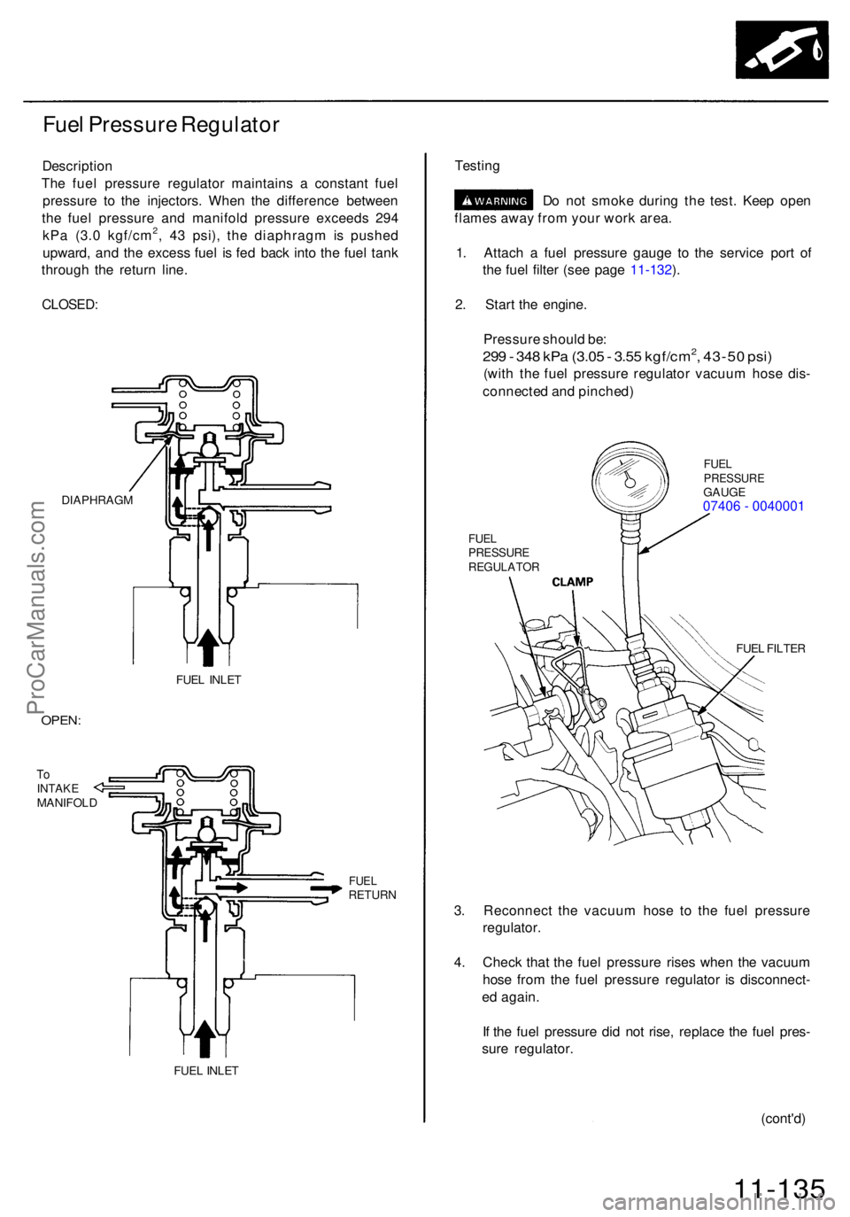
Fuel Pressur e Regulato r
Descriptio n
Th e fue l pressur e regulato r maintain s a constan t fue l
pressur e t o th e injectors . Whe n th e differenc e betwee n
th e fue l pressur e an d manifol d pressur e exceed s 29 4
kP a (3. 0 kgf/cm
2, 4 3 psi) , th e diaphrag m is pushe d
upward , an d th e exces s fue l i s fe d bac k int o th e fue l tan k
throug h th e retur n line .
DIAPHRAG M
FUEL INLE T
OPEN :
ToINTAK EMANIFOL D
FUELRETUR N
FUEL INLE T
Testin g
Do no t smok e durin g th e test . Kee p ope n
flame s awa y fro m you r wor k area .
1 . Attac h a fue l pressur e gaug e t o th e servic e por t o f
th e fue l filte r (se e pag e 11-132 ).
2 . Star t th e engine .
Pressur e shoul d be :
299 - 34 8 kP a (3.0 5 - 3.5 5 kgf/cm2, 43-5 0 psi )
(wit h th e fue l pressur e regulato r vacuu m hos e dis -
connecte d an d pinched )
FUELPRESSUR EGAUGE07406 - 0040001
FUELPRESSUR EREGULATO R
FUEL FILTE R
3. Reconnec t th e vacuu m hos e t o th e fue l pressur e
regulator .
4 . Chec k tha t th e fue l pressur e rise s whe n th e vacuu m
hos e fro m th e fue l pressur e regulato r i s disconnect -
e d again .
I f th e fue l pressur e di d no t rise , replac e th e fue l pres -
sur e regulator .
(cont'd)
11-135
CLOSED :
ProCarManuals.com
Page 637 of 1954

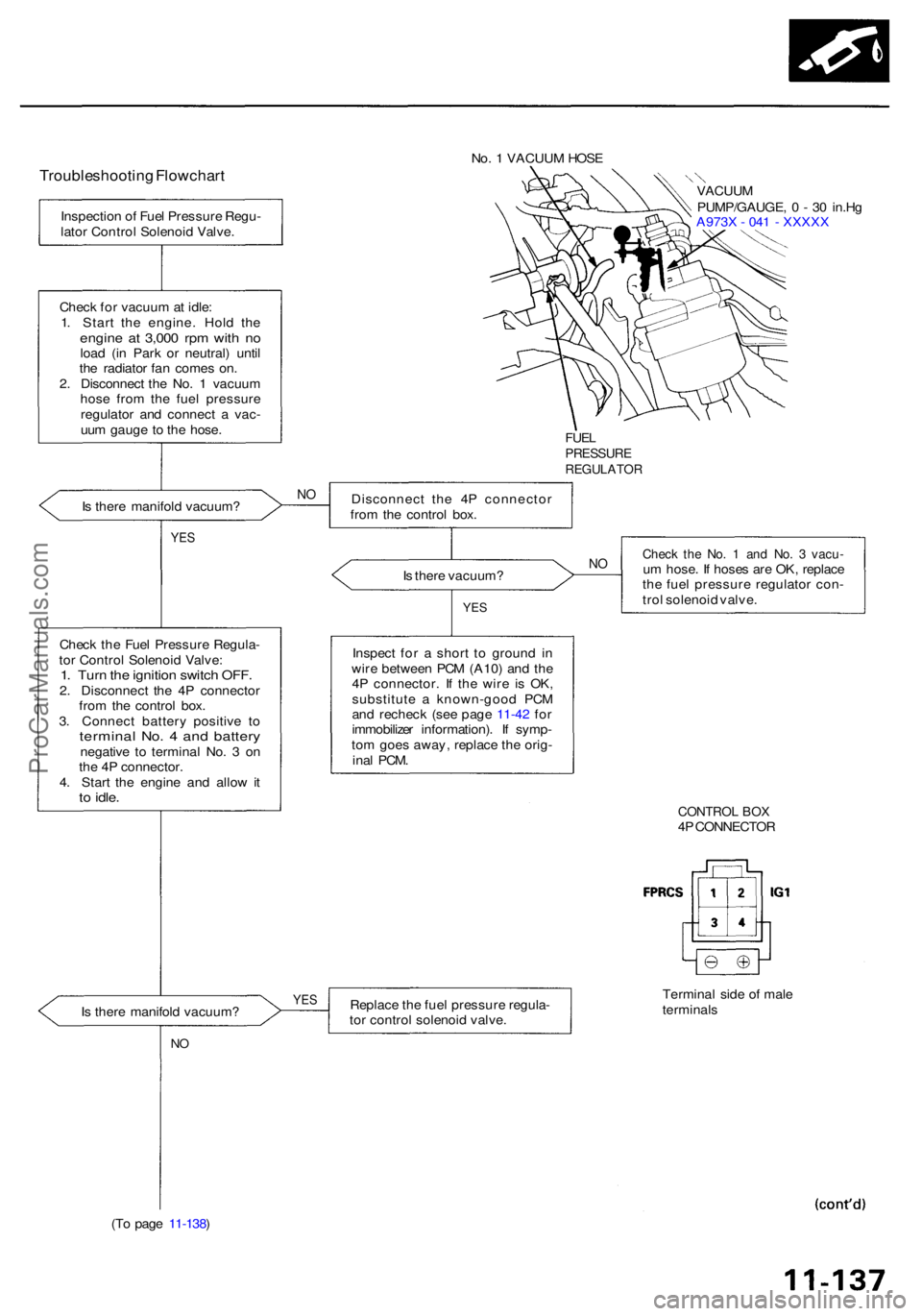
No. 1 VACUU M HOS E
Troubleshootin g Flowchar tVACUUM
PUMP/GAUGE , 0 - 3 0 in.H g
A973 X - 04 1 - XXXX X
FUELPRESSUR EREGULATO R
Is ther e manifol d vacuum ? Disconnec
t th e 4 P connecto r
fro m th e control box.
YES
Is ther e vacuum ?
Chec k th e Fue l Pressur e Regula -
to r Contro l Solenoi d Valve :
1. Tur n th e ignitio n switc h OFF .2. Disconnec t th e 4 P connecto r
fro m th e contro l box .
3 . Connec t batter y positiv e t o
termina l No . 4 an d batter ynegativ e t o termina l No . 3 on
th e 4 P connector .
4 . Star t th e engin e an d allo w it
to idle .
YES
Chec k th e No . 1 an d No . 3 vacu -um hose . I f hose s ar e OK , replac e
th e fue l pressur e regulato r con -
tro l solenoi d valve .
Inspec t fo r a shor t t o groun d i n
wir e betwee n PC M (A10 ) an d th e
4 P connector . I f th e wir e i s OK ,
substitut e a known-goo d PC M
an d rechec k (se e pag e 11-42 fo r
immobilize r information) . I f symp -
to m goe s away , replac e th e orig -
ina l PCM .
CONTRO L BO X4P CONNECTO R
I s ther e manifol d vacuum ? Replac
e th e fue l pressur e regula -
to r contro l solenoi d valve . Termina
l sid e o f mal e
terminal s
NO
(T o pag e 11-138 )
YES
NO
N
O
Inspectio n o f Fue l Pressur e Regu -
lato r Contro l Solenoi d Valve .
Chec k fo r vacuu m at idle :
1 . Star t th e engine . Hol d th e
engin e a t 3,00 0 rp m wit h n oloa d (i n Par k o r neutral ) unti l
th e radiato r fa n come s on .
2 . Disconnec t th e No . 1 vacuu m
hos e fro m th e fue l pressur e
regulato r an d connec t a vac -
uu m gaug e t o th e hose .
ProCarManuals.com
Page 639 of 1954

Fuel Pum p Rela y
Troubleshootin g Flowchar t
Inspection o f fue l pum p relay .
Turn th e ignitio n switc h t o th eSTAR T (III ) position .
Doe s th e engin e start ? Inspec
t th e fue l pum p resisto r
(se e pag e 11-141 ).
YE S
Chec k fo r a n ope n in th e circuit :
1 . Sto p th e engine .
2 . Tur n th e ignitio n switc h O N (II) .
3. Measur e voltag e betwee nPCM connecto r termina l C 4and bod y ground .
PCM CONNECTO R C (12P )
I s ther e batter y voltage ?
YES
Proble m verification :
1 . Star t th e engine . Hol d th e
engin e a t 3,00 0 rp m wit h n o
loa d (i n Par k o r neutral ) unti l
th e radiato r fa n come s on ,
the n le t i t idl e fo r a t leas t on e
minute .2. Tur n th e ignitio n switc h OFF .3. Disconnec t No . 2 1 hos e fro m
th e instal l pipe , an d connec t a
vacuu m pum p t o th e hose .
4 . Appl y vacuu m 2 7 t o 4 0 kp a
(200 t o SOOmmHg , 8 to 1 2in.Hg) .
5 . Star t th e engine .
6 . Hol d engin e spee d a t 6,50 0
rpm (transmissio n i n o rposition) .7. Measur e voltag e betwee n
PC M connecto r termina l C 4
an d bod y ground .
I s ther e les s tha n 1.0V ? (T
o pag e 11-140 )
Wire sid e o f femal e terminal s
No . 2 1 HOS E
VACUUM PUMP/GAUGE , 0 - 3 0 in.H g
A973X-041-XXXX X
Substitute a known-goo d PC M
an d rechec k (se e pag e 11-42 fo r
immobilize r information) . I f pre -
scribe d voltag e i s no w available ,
replac e th e origina l PCM .
Fue l pum p rela y circui t i s OK .
YES
NO
N O
NO
ProCarManuals.com