1996 ACURA RL KA9 radio
[x] Cancel search: radioPage 328 of 1954
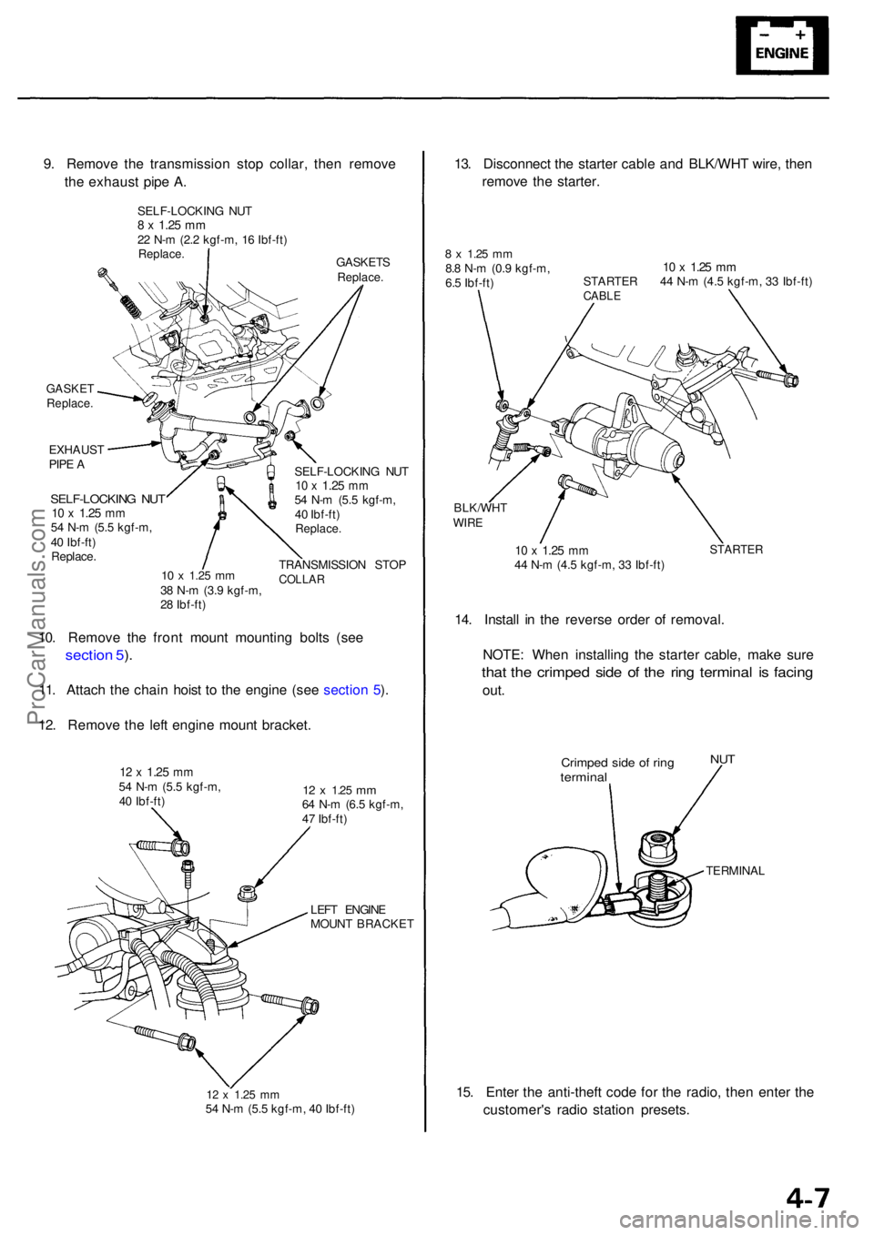
GASKETReplace .
EXHAUS T
PIP E A
SELF-LOCKIN G NU T10 x 1.2 5 mm54 N- m (5. 5 kgf-m ,
4 0 Ibf-ft )
Replace .
10 x 1.2 5 mm38 N- m (3. 9 kgf-m ,
2 8 Ibf-ft ) SELF-LOCKIN
G NU T
10 x 1.2 5 mm54 N- m (5. 5 kgf-m ,
4 0 Ibf-ft )
Replace .
TRANSMISSIO N STO PCOLLA R
10. Remov e th e fron t moun t mountin g bolt s (se e
sectio n 5 ).
11 . Attach the chai n hois t t o th e engine (see sectio n 5 ).
12 . Remov e th e lef t engin e moun t bracket .
12 x 1.2 5 mm54 N- m (5. 5 kgf-m ,
4 0 Ibf-ft )12 x 1.2 5 mm64 N- m (6. 5 kgf-m ,
4 7 Ibf-ft )
LEF T ENGIN E
MOUN T BRACKE T
12 x 1.2 5 mm54 N- m (5. 5 kgf-m , 4 0 Ibf-ft )
13. Disconnec t th e starte r cabl e an d BLK/WH T wire , the n
remov e th e starter .
8 x 1.2 5 mm8.8 N- m (0. 9 kgf-m ,
6. 5 Ibf-ft )10 x 1.2 5 mmSTARTE R 4 4 N- m (4. 5 kgf-m , 3 3 Ibf-ft )CABL E
BLK/WH TWIRE
10 x 1.2 5 mm44 N- m (4. 5 kgf-m , 3 3 Ibf-ft )STARTE R
14. Instal l i n th e revers e orde r o f removal .
NOTE : Whe n installin g th e starte r cable , mak e sur e
that th e crimpe d sid e o f th e rin g termina l i s facin g
out.
Crimpe d sid e o f rin gtermina l
NUT
TERMINA L
15. Ente r th e anti-theft code fo r th e radio , the n ente r th e
customer' s radi o statio n presets .
9
. Remov e th e transmissio n sto p collar , the n remov e
th e exhaus t pip e A .
GASKET SReplace.
SELF-LOCKIN G NU T8 x 1.2 5 mm22 N- m (2. 2 kgf-m , 1 6 Ibf-ft )Replace .
ProCarManuals.com
Page 348 of 1954

Alternator Replacemen t
1. Mak e sur e yo u hav e th e anti-thef t cod e fo r th e radio ,
the n writ e dow n th e frequencie s fo r th e radio' s pre -
se t buttons .
2 . Disconnec t th e batter y negativ e termina l first , the n
th e positiv e terminal .
NOTE : Th e PC M memor y mus t b e rese t afte r recon -
nectin g th e batter y (se e pag e 11-125 ).
3 . Remov e th e batter y an d batter y bas e (se e pag e 4-6 ).
4 . Remov e th e mountin g bolt , loc k bol t an d adjustin g
rod , the n remov e th e alternato r belt .
LOC K BOL T8 x 1.2 5 mm22 N- m (2. 2 kgf-m ,
1 6 Ibf-ft ) ADJUSTIN
GROD
ALTERNATO RBELT
MOUNTIN G BOL T10 x 1.2 5 mm44 N- m (4. 5 kgf-m ,33 Ibf-ft )
5. Remov e th e alternato r bracket .
ALTERNATO RBRACKET
10 x 1.2 5 mm44 N- m (4. 5 kgf-m ,
3 3 Ibf-ft )8 x 1.2 5 mm22 N- m (2. 2 kgf-m ,
1 6 Ibf-ft )
6.Disconnec t th e 4 P connecto r an d harnes s cli p bracket ,
the n remov e th e termina l nu t an d th e BL K wir e fro m
th e B terminal . Tak e ou t th e alternator .
BLK WIR E8 x 1.2 5 mm12 N- m (1.2 kgf-m ,
8. 7 Ibf-ft )
4 P CONNECTO R
ALTERNATO R
7. Instal l th e revers e orde r o f removal .
8 . Adjus t th e alternato r bel t (se e pag e 4-33 ).
9 . Ente r th e anti-thef t cod e fo r th e radio , the n ente r th e
customer' s radi o statio n presets .
ProCarManuals.com
Page 357 of 1954
Set/Resume/Cancel Switc h Test/Replacemen t
SRS component s ar e locate d in thi s area . Revie w th e SR S
componen t locations , precautions , an d procedure s i n th e
SR S (sectio n 24 ) befor e performin g repair s o r service .
1 . Mak e sur e yo u hav e th e anti-thef t cod e fo r th e radio ,
the n writ e dow n th e frequencie s fo r th e radio' s pre -
set buttons .
2. Disconnec t th e batter y negativ e cable , the n discon -
nec t th e positiv e cable , an d wai t a t leas t 3 minutes .
NOTE : Th e PC M memor y mus t b e rese t afte r recon -
necting th e batter y (se e pag e 11-125 ).
3 . Disconnec t th e airba g connectors .
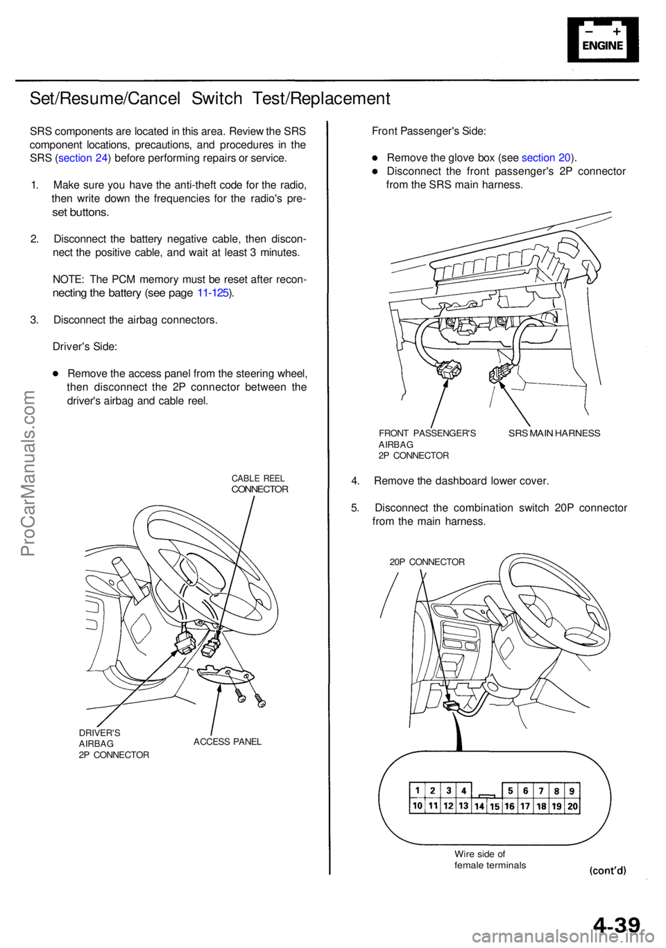
Driver' s Side :
Remov e th e acces s pane l fro m th e steerin g wheel ,
the n disconnec t th e 2 P connecto r betwee n th e
driver' s airba g an d cabl e reel .
CABL E REE LCONNECTO R
DRIVER'SAIRBAG2P CONNECTO RACCES
S PANE L
Front Passenger' s Side :
Remov e th e glov e bo x (se e sectio n 20 ).
Disconnec t th e fron t passenger' s 2 P connecto r
fro m th e SR S mai n harness .
FRONT PASSENGER' SAIRBAG2P CONNECTO R
SRS MAI N HARNES S
4. Remov e th e dashboar d lowe r cover .
5 . Disconnec t th e combinatio n switc h 20 P connecto r
fro m th e mai n harness .
20P CONNECTO R
Wire sid e o ffemal e terminal s
ProCarManuals.com
Page 358 of 1954
Cruise Control
Set/Resume/Cancel Switch Test/Replacement (cont'd)
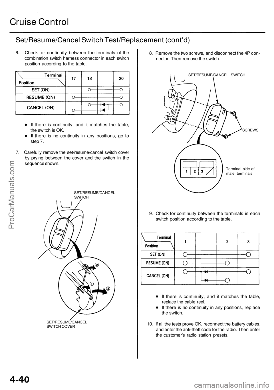
6. Check for continuity between the terminals of the
combination switch harness connector in each switch
position according to the table.
If there is continuity, and it matches the table,
the switch is OK.
If there is no continuity in any positions, go to
step 7.
7. Carefully remove the set/resume/cancel switch cover
by prying between the cover and the switch in the
sequence shown.
SET/RESUME/CANCEL
SWITCH
SET/RESUME/CANCEL
SWITCH COVER
8. Remove the two screws, and disconnect the 4P con-
nector. Then remove the switch.
SET/RESUME/CANCEL SWITCH
SCREWS
9. Check for continuity between the terminals in each
switch position according to the table.
If there is continuity, and it matches the table,
replace the cable reel.
If there is no continuity in any positions, replace
the switch.
10. If all the tests prove OK, reconnect the battery cables,
and enter the anti-theft code for the radio. Then enter
the customer's radio station presets.
Terminal side of
male terminalsProCarManuals.com
Page 365 of 1954
Engine Removal/Installatio n
Removal
Make sur e jack s an d safet y stand s ar e place d properl y
an d hois t bracket s ar e attache d to th e correc t position s
o n th e engine .
Mak e sur e th e vehicl e wil l no t rol l of f stand s an d fal l
whil e yo u ar e workin g unde r it .
CAUTION :
Us e fende r cover s t o avoi d damagin g painte d sur -
faces .
Unplu g th e wirin g connector s carefull y whil e holdin g
th e connecto r portio n to avoi d damage .
Mar k al l wirin g an d hose s t o avoi d misconnection .
Also , b e sur e tha t the y d o no t contac t othe r wirin g
o r hose s o r interfer e wit h othe r parts .
NOTE : D o th e PC M Memor y Settin g afte r reconnectin g
th e batter y (se e sectio n 11 ).
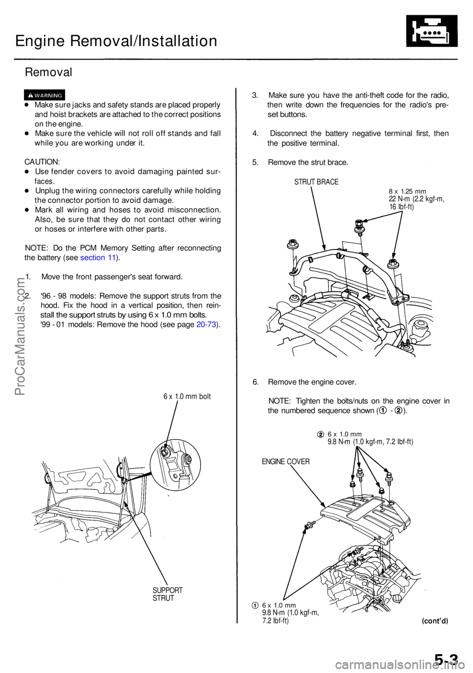
1 . Mov e th e fron t passenger' s sea t forward .
2 . '9 6 - 9 8 models : Remov e th e suppor t strut s fro m th e
hood . Fi x th e hoo d i n a vertica l position , the n rein -
stall th e suppor t strut s b y usin g 6 x 1. 0 m m bolts .
'99 - 0 1 models : Remov e th e hoo d (se e pag e 20-73 ).
6 x 1. 0 m m bol t
SUPPOR TSTRUT
3. Mak e sur e yo u hav e th e anti-thef t cod e fo r th e radio ,
the n writ e dow n th e frequencie s fo r th e radio' s pre -
set buttons .
4. Disconnec t th e batter y negativ e termina l first , the n
th e positiv e terminal .
5 . Remov e th e stru t brace .
STRUT BRAC E
8 x 1.2 5 mm22 N- m (2. 2 kgf-m ,16 Ibf-ft )
6. Remov e th e engin e cover .
NOTE : Tighte n th e bolts/nut s o n th e engin e cove r i n
th e numbere d sequenc e show n ( - ).
6 x 1. 0 m m9.8 N- m (1. 0 kgf-m , 7. 2 Ibf-ft )
ENGIN E COVE R
6 x 1. 0 m m9.8 N- m (1. 0 kgf-m ,7.2 Ibf-ft )
ProCarManuals.com
Page 378 of 1954

Engine Removal/Installatio n
Installation (cont'd )
5. Instal l th e transmissio n beam , the n tighte n th e bolt s
in th e numbere d sequenc e show n ( ) .
12 x 1.2 5 mm54 N- m (5. 5 kgf-m ,40 Ibf-ft )10 x 1.2 5 mm38 N- m (3. 9 kgf-m ,28 Ibf-ft )
10 x 1.2 5 mm38 N- m (3. 9 kgf-m ,28 Ibf-ft )
6. Tighte n th e lef t fron t moun t mountin g bolt .
12 x 1.2 5 mm74 N- m (7. 5 kgf-m ,52 Ibf-ft )
7. Tighte n th e righ t fron t moun t mountin g bolt .
12 x 1.2 5 mm74 N- m (7. 5 kgf-m ,52 Ibf-ft )
8. D o th e followin g check s an d adjustments :
Chec k tha t th e se t ring s o n th e end s o f th e drive -
shaf t an d intermediat e shaf t clic k int o place .
CAUTION : Us e ne w se t rings .
Adjus t th e shif t cabl e (se e sectio n 14 ).
Adjus t th e throttl e cabl e (se e sectio n 11 ).
Adjus t th e cruis e contro l cabl e (se e sectio n 4 ).
Refil l th e engin e wit h engin e oi l (se e pag e 8-4 ).
Refil l th e transmissio n wit h AT F (se e sectio n 14 ).
Refil l th e differentia l wit h differentia l oi l (se e
sectio n 15 ).
Refil l th e radiato r wit h engin e coolan t (se e pag e
10-5).
Blee d ai r fro m th e coolin g syste m a t th e blee d
bolt wit h th e heate r valv e ope n (se e pag e 10-5 ).
Clea n th e batter y post s an d cabl e terminal s wit h
sandpaper , assembl e them , the n appl y greas e to
preven t corrosion .
Inspec t fo r fue l leakag e (se e sectio n 11 ).
— Afte r assemblin g al l fue l lin e parts , tur n o n
th e ignitio n switc h (d o no t operat e th e starter )
s o tha t th e fue l pum p operate s fo r approxi -
matel y 2 second s an d pressurize s th e fue l
line .
— Repea t thi s operatio n 2 or 3 times , the n chec k
for fue l leakag e a t an y poin t i n th e fue l line .
Ente r th e anti-thef t cod e fo r th e radio , the n ente r
th e customer' s radi o statio n presets .
ProCarManuals.com
Page 401 of 1954
Cylinder Head s
Remova l
Make sur e jack s an d safet y stand s ar e
place d properl y an d hois t bracket s ar e attache d t o th e
correc t position s o n th e engine .
CAUTION :
Us e fende r cover s t o avoi d damagin g painte d sur -
faces .
Unplu g th e wirin g connector s carefull y whil e holdin g
th e connecto r portio n to avoi d damage .
T o avoi d damagin g th e cylinde r head , wai t unti l th e
engin e coolan t temperatur e drop s belo w 100° F (38°C )
befor e loosenin g th e retainin g bolts .
NOTE :
Unspecifie d item s ar e common .
Mar k al l wirin g an d hose s t o avoi d misconnection .
Also , b e sur e tha t the y d o no t contac t othe r wirin g o r
hose s o r interfer e wit h othe r parts .
Inspec t th e timin g bel t befor e removin g th e cylinde r
head.
Turn th e crankshaf t pulle y s o tha t th e No . 1 pisto n i s
a t to p dea d cente r (TDC) .
D o th e PC M Memor y Settin g afte r reconnectin g th e
batter y (se e sectio n 11 ).
1 . Remov e th e suppor t strut s fro m th e hood . Fi x th e
hoo d i n a vertica l position , the n reinstal l th e sup -
por t strut s b y usin g 6 x 1. 0 m m bolt s (se e pag e 5-3 ).
2 . Mak e sur e yo u hav e th e anti-thef t cod e fo r th e radio ,
the n writ e dow n th e frequencie s fo r th e radio' s pre -
set buttons .
3. Disconnec t th e batter y negativ e termina l first , the n
th e positiv e terminal .
4 . Drai n th e engin e coolan t (se e pag e 10-5 ).
5 . Remov e th e stru t brac e (se e pag e 5-3 ).
6 . Remov e th e engine cover (se e pag e 5-3 ).
7 . Remov e th e intak e ai r duc t an d ai r cleane r housin g
assembl y (se e pag e 5-4 ). 8
. Remov e th e throttl e cove r (se e pag e 5-4 ).
9 . Remov e th e throttl e cabl e an d cruis e contro l cabl e
b y loosenin g th e locknuts , the n sli p th e cabl e end s
ou t o f th e accelerato r linkag e (se e pag e 5-4 ).
NOTE :
Take car e no t t o ben d th e cabl e whe n removin g
it . Alway s replac e an y kinke d cabl e wit h a ne w
one .
Adjus t th e throttl e cabl e whe n installin g (se e
sectio n 11 ).
Adjus t th e cruis e contro l cabl e whe n installin g
(se e sectio n 23 ).
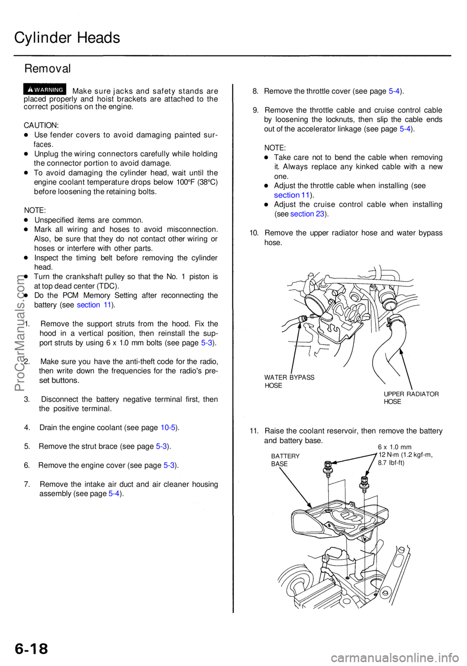
10 . Remov e th e uppe r radiato r hos e an d wate r bypas s
hose.
WATE R BYPAS SHOSEUPPE R RADIATO RHOSE
11. Rais e th e coolan t reservoir , the n remov e th e batter y
an d batter y base .
BATTER YBASE
6 x 1. 0 m m12 N- m (1. 2 kgf-m ,8.7 Ibf-ft )
ProCarManuals.com
Page 428 of 1954
Cylinder Head s
Installatio n (cont'd )
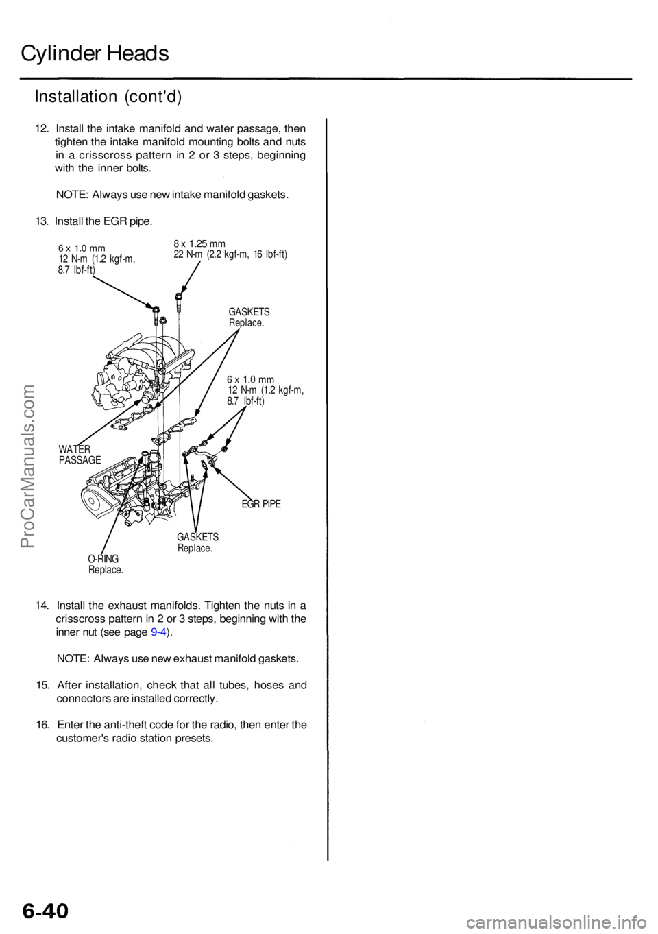
12. Instal l th e intak e manifol d an d wate r passage , the n
tighte n th e intak e manifol d mountin g bolt s an d nut s
i n a crisscros s patter n i n 2 o r 3 steps , beginnin g
wit h th e inne r bolts .
NOTE : Alway s us e ne w intak e manifol d gaskets .
13 . Instal l th e EG R pipe .
6 x 1. 0 m m12 N- m (1. 2 kgf-m ,
8. 7 Ibf-ft )
8 x 1.2 5 mm22 N- m (2. 2 kgf-m , 1 6 Ibf-ft )
GASKET S
Replace.
6 x 1. 0 m m12 N- m (1. 2 kgf-m ,
8. 7 Ibf-ft )
WATE R
PASSAG E
EGR PIP E
GASKET S
Replace.O-RING
Replace .
14. Instal l th e exhaus t manifolds . Tighte n th e nut s i n a
crisscros s patter n in 2 or 3 steps , beginnin g wit h th e
inne r nu t (se e pag e 9-4 ).
NOTE : Alway s us e ne w exhaus t manifol d gaskets .
15 . Afte r installation , chec k tha t al l tubes , hose s an d
connector s ar e installe d correctly .
16 . Ente r th e anti-thef t cod e fo r th e radio , the n ente r th e
customer' s radi o statio n presets .
ProCarManuals.com