1996 ACURA RL KA9 radio
[x] Cancel search: radioPage 513 of 1954
System Descriptio n
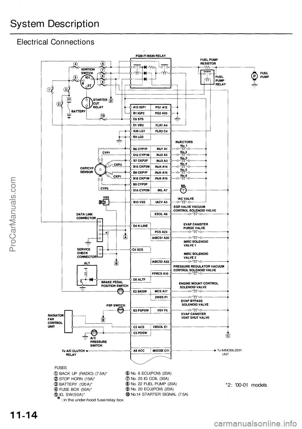
Electrical Connection s
FUSES
BACK U P (RADIO ) (7.5A) *
STO P HOR N (15A) *
BATTER Y (12 0 A) *
FUS E BO X (50A) *
IG . SW(50A) *
: i n th e under-hoo d fuse/rela y bo x
No. 6 ECU(PCM ) (20A )
No . 2 5 IG COI L (30A )
No . 2 2 FUE L PUM P (20A )
No . 2 0 ECU(PCM ) (20A )
No.1 4 STARTE R SIGNA L (7.5A )
*2: '00-0 1 model s
To IMMOBILIZE RUNIT
ProCarManuals.com
Page 625 of 1954
PCM Memory Setting
NOTE: The PCM reset procedure and disconnecting the
battery or the BACK UP RADIO (7.5 A) fuse cancels the
PCM memory for idle control. The following procedure
is needed after the PCM reset procedure and reconnect-
ing the battery or the BACK UP RADIO (7.5 A) fuse.
1. Start the engine. Hold the engine at 3,000 rpm with
no load (in Park or neutral) until the radiator fan
comes on.
2. Let the engine idle for approx. 5 minutes under the
following conditions:
• Transmission in Park or neutral
• A/C switch OFF
• Headlights OFF
• Rear defogger OFFProCarManuals.com
Page 632 of 1954

Fuel Suppl y Syste m
System Descriptio n
The fue l suppl y syste m consist s o f a fue l tank , in-tan k
high-pressur e fue l pump , PGM-F I mai n relay , fue l filter ,
fue l pressur e regulator , fue l pressur e regulato r contro l
solenoi d valve , injectors , an d fue l deliver y an d retur n
lines . Thi s syste m deliver s pressure-regulate d fue l t o th e
injector s an d cut s th e fue l deliver y whe n th e engin e i s
no t running .
Fuel Pressur e
Relieving
Befor e disconnectin g fue l pipe s o r hoses , releas e pres -
sur e fro m th e syste m b y loosenin g th e servic e bol t o n
top o f th e fue l filter .
SERVIC E
BOL T
12 N- m(1.2 kgf-m , 8. 7 Ibf-ft )
FUE L
FILTE R
SHOP TOWE L
NOTE:
• A fue l pressur e gaug e can be attache d a t th e ser -
vic e bol t hole .
• Alway s replac e th e washe r betwee n th e servic e
bol t an d th e specia l banj o bol t wheneve r th e ser -
vic e bol t i s loosened .
• Replac e al l washer s wheneve r th e bolt s ar e
removed . Inspectio
n
1 . Reliev e fue l pressure .
2 . Remov e th e servic e bol t o n th e fue l filte r whil e hold -
in g th e banj o bol t wit h anothe r wrench . Attac h th e
specia l tool .
FUEL FILTE R
3. Star t th e engine . Measur e th e fue l pressur e wit h th e
engin e idlin g an d th e vacuu m hos e o f th e fue l pres -
sur e regulato r disconnecte d fro m th e fue l pressur e
regulato r an d pinched . I f th e engin e wil l no t start ,
turn th e ignitio n switc h O N (II) , wai t fo r tw o sec -
onds , tur n i t OFF , the n bac k o n agai n an d rea d th e
fue l pressure .
Pressur e shoul d be :
29 9 - 34 8 kP a (3.0 5 - 3.5 5 kgf/cm
2, 43. 4 - 50. 5 psi )
4 . Reconnec t vacuu m hos e to th e fue l pressur e regula -
tor.
Pressur e shoul d be :
24 0 - 28 9 kP a (2.4 5 - 2.9 5 kgf/cm2, 34. 8 - 41. 9 psi )
I f th e fue l pressur e i s no t a s specified , firs t chec k th e
fue l pum p (se e pag e 11-142 ). I f th e fue l pum p is OK ,
chec k th e following :
• I f th e fue l pressur e i s highe r tha n specified ,
inspec t for :
— Pinche d o r clogge d fue l retur n hos e o r line .
— Fault y fue l pressur e regulato r (se e pag e
11-135 ).
• I f th e fue l pressur e i s lowe r tha n specified , inspec t
for:
— Clogge d fue l filter .
— Fault y fue l pressur e regulato r (se e pag e
11-135 ).
— Fue l lin e leakage .
1
. Mak e sur e yo u hav e th e anti-thef t cod e fo r th e
radio , the n writ e dow n th e frequencie s fo r th e
radio' s prese t buttons .
2 . Disconnec t th e batter y negativ e cabl e fro m th e bat -
ter y negativ e terminal .
3. Remov e th e fue l fil l cap .
4. Us e a bo x en d wrenc h o n th e servic e bol t a t th e fue l
filte r whil e holdin g th e specia l banj o bol t wit h
anothe r wrench .
5. Plac e a ra g o r sho p towe l ove r th e servic e bolt .
6 . Slowl y loose n th e servic e bol t on e complet e turn .
7 . Reconnec t th e battery , ente r th e anti-thef t cod e fo r
th e radio , the n ente r th e customer' s radi o statio n
presets .
•
D o no t smok e whil e workin g o n th e fue l system .
Kee p ope n flame s o r spark s awa y fro m you r wor k area .
• B e sur e t o reliev e fue l pressur e whil e th e ignitio n
switch is off .
CLAM P
FUE
L
PRESSUR E
REGULATO R FUE
L
PRESSUR E
GAUG E
07406-004000 1
ProCarManuals.com
Page 759 of 1954

Troubleshooting Procedure s
Checking th e Diagnosti c Troubl e Cod e (DTC )
wit h a n OB D II Sca n Too l o r Hond a PG M Teste r
When th e PC M sense s a n abnormalit y i n th e inpu t o r outpu t systems , th e indicato r ligh t i n th e gaug e assembl y wil l
blink . Whe n th e 16 P Dat a Lin k Connecto r (DLC ) (locate d behin d th e ashtray ) i s connecte d to th e OB D II Sca n Too l o r Hond a
PG M Teste r a s shown , th e sca n too l o r teste r wil l indicat e th e Diagnosti c Troubl e Cod e (DTC ) whe n th e ignitio n switc h i s
turne d O N (II) .
If th e indicato r ligh t o r th e MI L ha s bee n reporte d on , o r i f a driveabilit y proble m is suspected , follo w thi s procedure :
1 . Connec t th e OB D II Sca n Too l (conformin g to SA E J1978 ) o r Hond a PG M Teste r t o th e 16 P DLC .
(Se e th e OB D II Sca n Too l o r Hond a PG M Teste r user' s manua l fo r specifi c instructions . I f yo u ar e usin g th e Hond a
PG M Tester , mak e sur e it i s se t t o th e SA E DT C type. )
2 . Tur n th e ignitio n switc h O N (II) , an d observ e th e DT C o n th e screen .
3 . Recor d al l fue l an d emission s DTCs , A/ T DTCs , an d freez e data .
4 . I f ther e is a fue l an d emission s DTC , firs t chec k th e fue l an d emission s syste m a s indicate d b y th e DT C (excep t fo r DT C
P0700) . DT C P070 0 mean s ther e is on e o r mor e A/ T DTC , an d n o problem s wer e detecte d in th e fue l an d emission s circui t
of th e PCM .
5. Ge t th e anti-thef t cod e fo r th e radio , the n writ e dow n th e radi o statio n presets .
6 . Rese t th e memor y wit h th e PG M Teste r o r b y removin g th e BAC K U P fus e i n th e under-hoo d fuse/rela y bo x fo r mor e
tha n 1 0 seconds .
7 . Driv e th e vehicl e fo r severa l minute s a t speed s ove r 3 0 mp h (5 0 km/h) , an d the n rechec k fo r DTCs . I f th e A/ T DT C
returns , g o t o th e Symptom-to-Componen t Char t (pag e 14-5 6 an d 14-57 ). I f th e DT C doe s no t return , ther e wa s a n inter -
mitten t proble m withi n th e circuit . Mak e sur e al l pin s an d terminal s i n th e circui t ar e tight , an d the n g o t o ste p 8 .
8 . Ente r th e anti-thef t cod e fo r th e radio , rese t th e radi o prese t stations , an d se t th e clock .
ProCarManuals.com
Page 762 of 1954

PCM Rese t Procedur e
1 . Mak e sur e yo u hav e th e anti-thef t cod e fo r th e radio , the n writ e dow n th e frequencie s fo r th e radio' s prese t buttons .
2 . Tur n th e ignitio n switc h OFF .
3 . Remov e th e No . 5 6 BAC K UP , RADI O fus e (7. 5 A ) fro m th e under-hoo d fuse/rela y bo x fo r 1 0 second s t o rese t th e PCM .
NOTE :
• Th e A/ T contro l syste m memor y canno t b e cleare d b y usin g th e OB D II Sca n Too l o r Hond a PG M Tester ; b e sur e t o
remov e th e BAC K UP , RADI O fus e t o rese t th e A/ T contro l syste m memory .
• Th e PC M memor y mus t b e rese t afte r reconnectin g th e batter y o r th e BAC K UP , RADI O fus e (se e pag e 11-111 ).
BAC K UP , RADI O(7.5 A ) FUS E
UNDER-HOO DFUSE/RELAY BO XFina l Procedur e
NOTE : Thi s procedur e mus t b e don e afte r an y troubleshooting .
1 . Tur n th e ignitio n switc h OFF .
2 . Disconnec t th e OB D II Sca n Too l o r Hond a PG M Teste r fro m th e Dat a Lin k Connecto r (16P) , o r remov e th e specia l too l
fro m th e Servic e Chec k Connector .
3. Rese t th e PCM .
4. Tur n th e ignitio n switc h O N (II) .
5 . Ente r th e anti-thef t cod e fo r th e radio , the n ente r th e customer' s radi o statio n presets .
6 . Memoriz e th e engin e idl e spee d signa l i n th e PC M (se e pag e 11-111 ).
ProCarManuals.com
Page 823 of 1954
Transmission
Removal
Make sur e lift s ar e place d properl y an d
hois t bracket s ar e attache d t o th e correc t positio n o n
th e engin e (se e sectio n 1 ).
CAUTION : Us e fende r cover s t o avoi d damagin g paint -
ed surfaces .
NOTE: Th e PC M memor y mus t b e rese t afte r reconnectin g
th e batter y o r th e BAC K UP , RADI O fus e (se e pag e 11-125 ).
1 . Befor e yo u disconnec t power , mak e sur e yo u hav e
th e anti-thef t cod e fo r th e radio , the n writ e dow n
the frequencie s fo r th e radio' s prese t buttons .
2. Disconnec t th e batter y negativ e (- ) termina l fro m
th e battery , the n remov e th e positiv e (+ ) terminal .
3. Shif t th e transmissio n int o th e position .
4 . Remov e th e stru t brace .
5 . Remov e th e contro l box .
CAUTION : D o no t remov e th e vacuu m tube s fro m
th e contro l box .
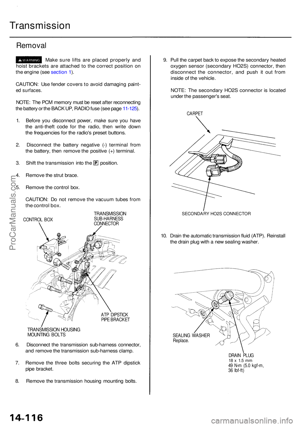
CONTRO L BO X
TRANSMISSIO NSUB-HARNESS
CONNECTO R
AT P DIPSTIC K
PIP E BRACKE T
9. Pul l th e carpe t bac k to expos e th e secondar y heate d
oxyge n senso r (secondar y HO2S ) connector, then
disconnec t th e connector , an d pus h i t ou t fro m
insid e o f th e vehicle .
NOTE : Th e secondar y HO2 S connecto r i s locate d
unde r th e passenger' s seat .
CARPE T
SECONDARY HO2S CONNECTOR
10. Drai n th e automati c transmissio n flui d (ATP) . Reinstal l
th e drai n plu g wit h a ne w sealin g washer .
SEALIN G WASHE R
Replace .
DRAIN PLU G
18 x 1. 5 m m49 N- m (5. 0 kgf-m ,
3 6 Ibf-ft )
6. Disconnec t th e transmissio n sub-harnes s connector ,
an d remov e th e transmissio n sub-harnes s clamp .
7 . Remov e th e thre e bolt s securin g th e AT P dipstic k
pip e bracket .
8 . Remov e th e transmissio n housin g mountin g bolts .
TRANSMISSIO N HOUSIN GMOUNTIN G BOLT S
ProCarManuals.com
Page 903 of 1954
Transmission
Installation (cont'd )
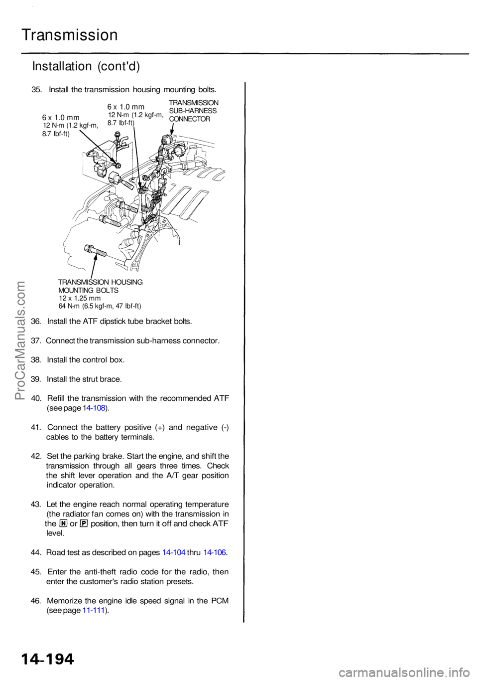
TRANSMISSIO N HOUSIN GMOUNTIN G BOLT S12 x 1.2 5 m m64 N- m (6. 5 kgf-m , 4 7 Ibf-ft )
36. Instal l th e AT F dipstic k tub e bracke t bolts .
37 . Connec t th e transmissio n sub-harnes s connector .
38 . Instal l th e contro l box .
39 . Instal l th e stru t brace .
40 . Refil l th e transmissio n wit h th e recommende d AT F
(se e pag e 1 4-108 ).
41 . Connec t th e batter y positiv e (+ ) an d negativ e (- )
cable s t o th e batter y terminals .
42 . Se t th e parkin g brake . Star t th e engine , an d shif t th e
transmissio n throug h al l gear s thre e times . Chec k
th e shif t leve r operatio n an d th e A/ T gea r positio n
indicato r operation .
43 . Le t th e engin e reac h norma l operatin g temperatur e
(th e radiato r fa n come s on ) wit h th e transmissio n in
th e o r position , the n tur n it of f an d chec k AT F
level .
44 . Roa d tes t a s describe d o n page s 14-10 4 thr u 14-106 .
45 . Ente r th e anti-thef t radi o cod e fo r th e radio , the n
ente r th e customer' s radi o statio n presets .
46 . Memoriz e th e engin e idl e spee d signa l i n th e PC M
(se e pag e 11-111 ).
35
. Instal l th e transmissio n housin g mountin g bolts .
TRANSMISSIO NSUB-HARNES SCONNECTOR
6 x 1. 0 m m12 N- m (1. 2 kgf-m ,8.7 Ibf-ft )6 x 1. 0 m m12 N- m (1. 2 kgf-m ,8.7 Ibf-ft )
ProCarManuals.com
Page 1084 of 1954
Troubleshooting Precautions
ABS Indicator Light:
The ABS indicator light comes on for 3 seconds and then goes off when the control unit detects no problem during the ini-
tial diagnosis right after the engine starts. However, the ABS indicator light can stay on for up to 40 seconds when the
control unit starts to check for pump overrun, etc. during the initial diagnosis. The ABS indicator light comes on, and the
ABS control unit memorizes the diagnostic trouble code (DTC) under certain conditions.
The parking brake is applied for more than 30 seconds while the vehicle is being driven. (DTC 2-1)
The transmission downshifted excessively. (DTC 4-1, 4-2)
The vehicle loses traction, and the front wheels spin for more than 1 minute when starting from a stuck condition on a
muddy, snowy, or sandy road. (DTC 4-8)
Tire adhesion is lost due to excessive cornering speed. (DTC 5, 5-4, 5-8)
The vehicle is driven on an extremely rough road. (DTC 8-1)
The vehicle is interfered by strong radio waves (noise), for example, illegal radio, etc. (DTC 8-2)
NOTE: If there is any trouble in the system, the ABS indicator light comes on during driving.
Diagnostic Trouble Code (DTC):
When the control unit detects a problem and the ABS indicator light comes on, the control unit memorizes the DTC.
The control unit has three memory registers. When a problem occurs, the control unit stores the DTC in the first memory
register. If another problem occurs, or the same problem occurs again, the control unit moves the first DTC to the next
memory register, and stores the second DTC in the first register. If there's a third problem occurrence, the two existing
DTCs are moved up one register, and the third DTC is stored in the first register. If problems continue to occur, the oldest
problem is moved out of the last register and lost, and the most recent problem is stored in the first register. When the
same problem occurs three times, the same DTC is stored in all memory registers. (Refer to the Symptom-to-System
Chart for diagnostic period.)
The most recent DTC is indicated first, and the oldest DTC is indicated last.
The DTCs are erased from the control unit when the ABS control unit +B2 power supply or connector is disconnected.
The control unit's memory can be erased by disconnecting the ABS B2 fuse for more than 3 seconds.
Self-diagnosis:
There are three self-diagnoses described below.
Initial diagnosis: Performed right after the engine starts until the ABS indicator light goes off.
Regular diagnosis: Continuously performed (under some conditions) after the ABS indicator light goes off until the
engine stops.
Individual part/system diagnosis: Diagnosis about a specific part/system under its operating conditions.
The CPU (central processing unit) controls the following when it detects a problem during self-diagnosis:
Turns the ABS indicator light ON.
Turns the front and rear fail-safe relays off.
Stops the ABS control.
Stops the ABS pump. (The pump may work under some conditions.)
After the DTC is stored in the control unit, the CPU stops self-diagnosis.ProCarManuals.com