Page 1495 of 1954
Compressor
Replacemen t (cont'd )
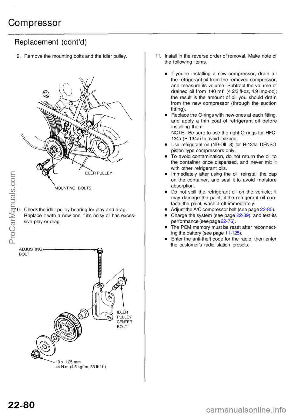
9. Remov e th e mountin g bolt s an d th e idle r pulley .
IDLER PULLE Y
MOUNTIN G BOLT S
10. Chec k th e idle r pulle y bearin g fo r pla y an d drag .
Replac e it wit h a ne w on e i f it' s nois y o r ha s exces -
siv e pla y o r drag .
ADJUSTIN GBOLT
IDLE RPULLE YCENTE RBOLT
10 x 1.2 5 mm44 N- m (4. 5 kgf-m , 3 3 Ibf-ft )
11. Instal l i n th e revers e orde r o f removal . Mak e not e o f
th e followin g items .
I f you'r e installin g a ne w compressor , drai n al l
th e refrigeran t oi l fro m th e remove d compressor ,
an d measur e it s volume . Subtrac t th e volum e o f
draine d oi l fro m 14 0 m ( 4 2/ 3 fl-oz , 4. 9 Imp-oz) ;
th e resul t i s th e amoun t o f oi l yo u shoul d drai n
fro m th e ne w compresso r (throug h th e suctio n
fitting).
Replac e th e O-ring s wit h ne w one s a t eac h fitting ,
an d appl y a thi n coa t o f refrigeran t oi l befor e
installin g them .
NOTE : B e sur e t o us e th e righ t O-ring s fo r HFC -
134a (R-134a ) t o avoi d leakage .
Use refrigeran t oi l (ND-OI L 8 ) fo r R-134 a DENS O
piston typ e compressor s only .
To avoi d contamination , d o no t retur n th e oi l t o
th e containe r onc e dispensed , an d neve r mi x i t
wit h othe r refrigeran t oils .
Immediatel y afte r usin g th e oil , reinstal l th e ca p
o n th e container , an d sea l i t t o avoi d moistur e
absorption .
D o no t spil l th e refrigeran t oi l o n th e vehicle ; i t
ma y damag e th e paint ; i f th e refrigeran t oi l con -
tact s th e paint , was h it of f immediately .
Adjus t th e A/ C compresso r bel t (se e pag e 22-85 ).
Charg e th e syste m (se e pag e 22-89 ), an d tes t it s
performanc e (se e pag e 22-76 ).
Th e PC M memor y mus t b e rese t afte r reconnect -
in g th e batter y (se e pag e 11-125 ).
Ente r th e anti-thef t cod e fo r th e radio , the n ente r
th e customer' s radi o statio n presets .
ProCarManuals.com
Page 1516 of 1954
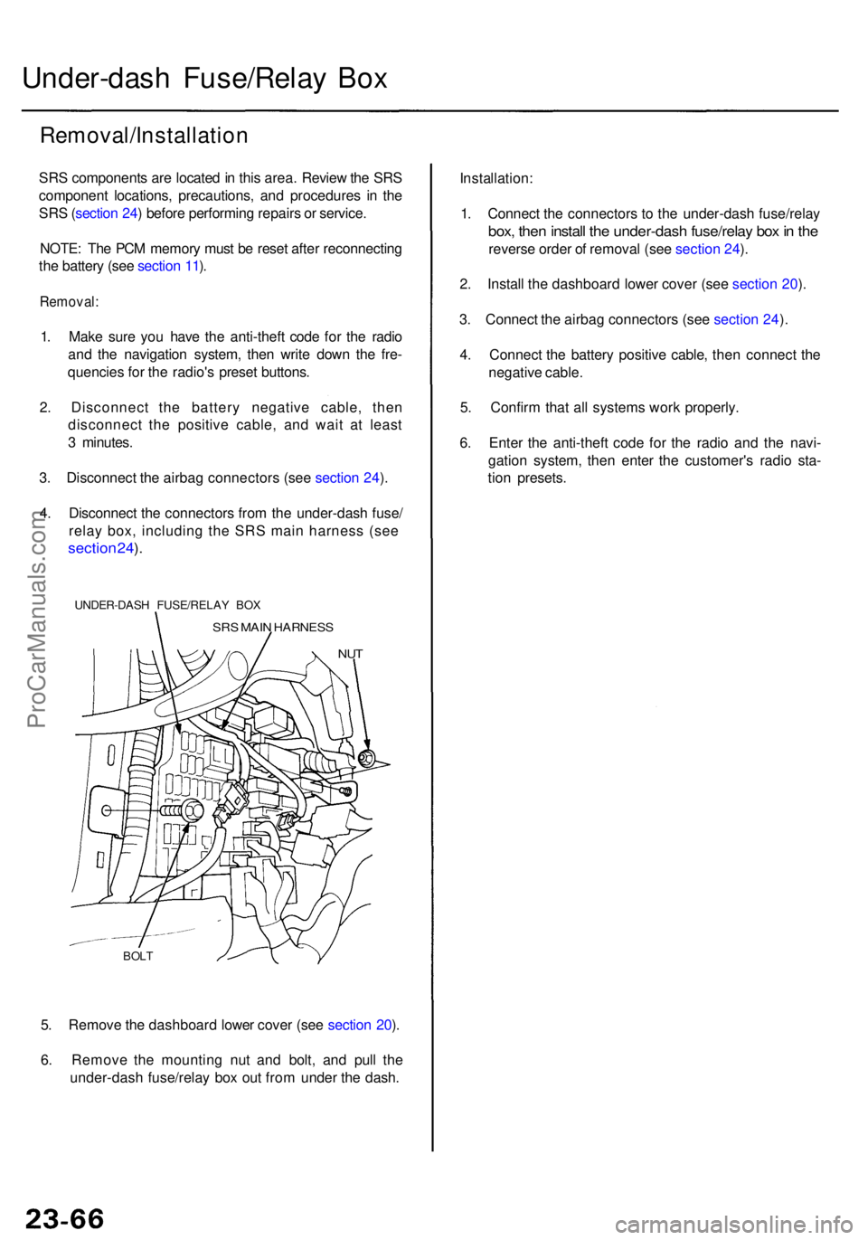
5. Remov e th e dashboar d lowe r cove r (se e sectio n 20 ).
6 . Remov e th e mountin g nu t an d bolt , an d pul l th e
under-das h fuse/rela y bo x ou t fro m unde r th e dash .
BOLT
Under-das h Fuse/Rela y Bo x
Removal/Installatio n
SRS component s ar e locate d in thi s area . Revie w th e SR S
componen t locations , precautions , an d procedure s i n th e
SR S (sectio n 24 ) befor e performin g repair s o r service .
NOTE : Th e PC M memor y mus t b e rese t afte r reconnectin g
th e batter y (se e sectio n 11 ).
Removal :
1. Mak e sur e yo u hav e th e anti-thef t cod e fo r th e radi o
an d th e navigatio n system , the n writ e dow n th e fre -
quencie s fo r th e radio' s prese t buttons .
2 . Disconnec t th e batter y negativ e cable , the n
disconnec t th e positiv e cable , an d wai t a t leas t
3 minutes .
3 . Disconnec t th e airba g connector s (se e sectio n 24 ).
4 . Disconnec t th e connector s fro m th e under-das h fuse /
relay box, including the SRS main harness (see
sectio n 24 ).
UNDER-DAS H FUSE/RELA Y BO X
SRS MAI N HARNES S
NUT
Installation :
1 . Connec t th e connector s t o th e under-das h fuse/rela y
box, the n instal l th e under-das h fuse/rela y bo x in th e
revers e orde r o f remova l (se e sectio n 24 ).
2 . Instal l th e dashboar d lowe r cove r (se e sectio n 20 ).
3 . Connec t th e airba g connector s (se e sectio n 24 ).
4 . Connec t th e batter y positiv e cable , the n connec t th e
negativ e cable .
5 . Confir m tha t al l system s wor k properly .
6 . Ente r th e anti-thef t cod e fo r th e radi o an d th e navi -
gatio n system , the n ente r th e customer' s radi o sta -
tio n presets .
ProCarManuals.com
Page 1520 of 1954
Ignition Switc h
Test
SRS component s ar e locate d i n thi s area . Revie w th e
SR S componen t locations , precautions , an d procedure s
i n th e SR S ( sectio n 24 ) befor e performin g repair s o r
service .
NOTE: Th e PC M memor y mus t b e rese t afte r reconnectin g
th e batter y (se e sectio n 11 ).
1 . Mak e sur e yo u hav e th e anti-thef t cod e fo r th e radi o
an d th e navigatio n system , the n writ e dow n th e fre -
quencie s fo r th e radio' s prese t buttons .
2 . Disconnec t th e batter y negativ e cable .
3 . Remov e th e dashboar d lowe r cove r (se e sectio n 20 ).
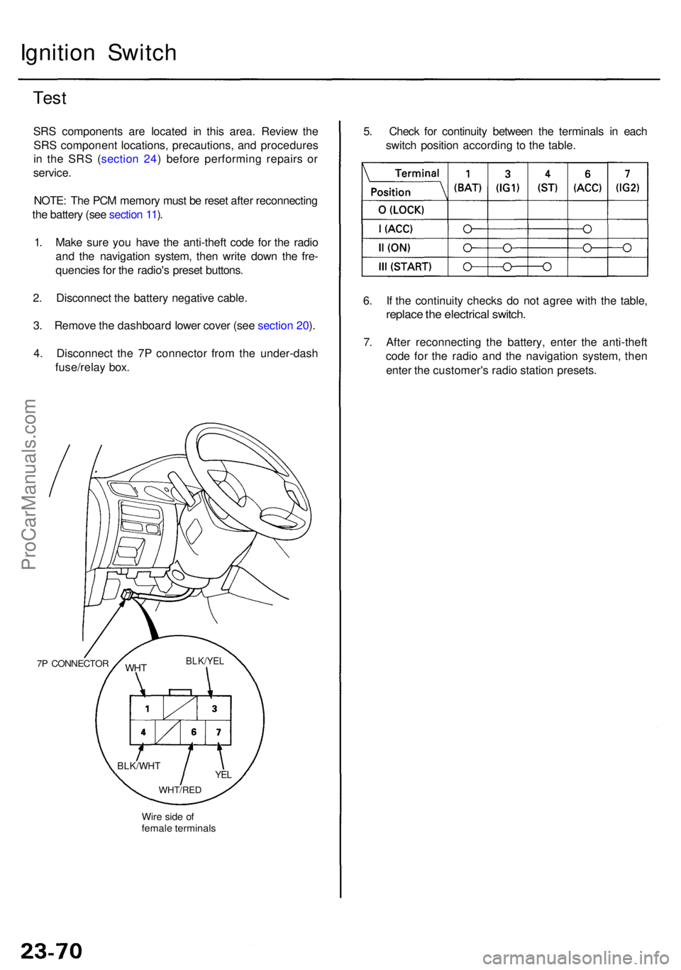
4 . Disconnec t th e 7 P connecto r fro m th e under-das h
fuse/rela y box .
7P CONNECTO R
Wire sid e o f
femal e terminal s
WHTBLK/YE L
YEL
WHT/RE D
BLK/WH T
5. Chec k fo r continuit y betwee n th e terminal s i n eac h
switc h positio n accordin g t o th e table .
6 . I f th e continuit y check s d o no t agre e wit h th e table ,
replac e th e electrica l switch .
7. Afte r reconnectin g th e battery , ente r th e anti-thef t
cod e fo r th e radi o an d th e navigatio n system , the n
ente r th e customer' s radi o statio n presets .
ProCarManuals.com
Page 1521 of 1954
8. Afte r reconnectin g th e battery , ente r th e anti-thef t
cod e fo r th e radi o an d th e navigatio n system , the n
ente r th e customer' s radi o statio n presets .
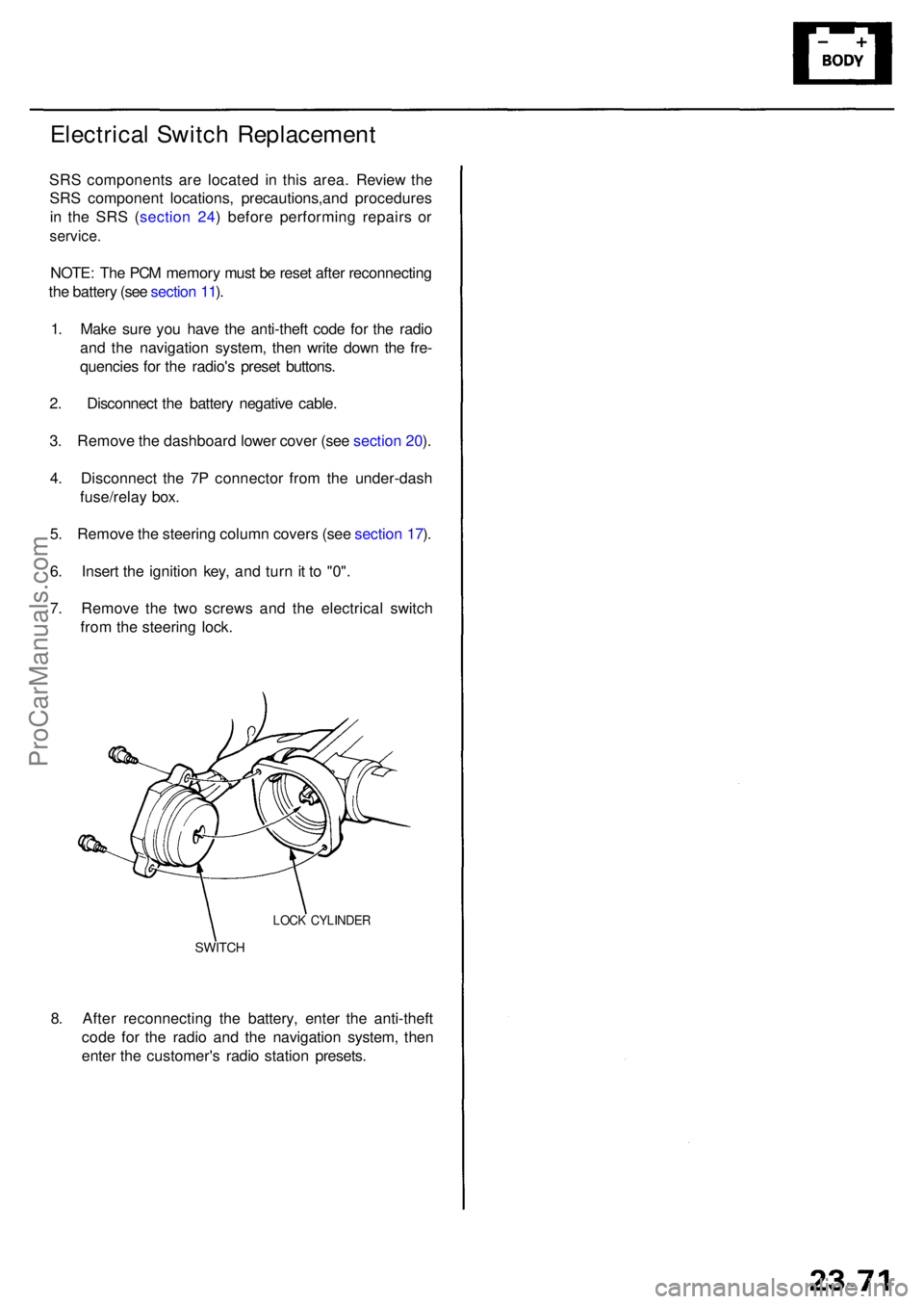
SWITCH
LOCK CYLINDE R
Electrical Switc h Replacemen t
SRS component s ar e locate d i n thi s area . Review the
SR S componen t locations , precautions,an d procedure s
i n th e SR S ( sectio n 24 ) befor e performin g repair s o r
service .
NOTE: Th e PC M memor y mus t b e rese t afte r reconnectin g
th e batter y (se e sectio n 11 ).
1 . Mak e sur e yo u hav e th e anti-thef t cod e fo r th e radi o
an d th e navigatio n system , the n writ e dow n th e fre -
quencie s fo r th e radio' s prese t buttons .
2 . Disconnec t th e batter y negativ e cable .
3 . Remov e th e dashboar d lowe r cove r (se e sectio n 20 ).
4 . Disconnec t th e 7 P connecto r fro m th e under-das h
fuse/rela y box .
5 . Remov e th e steerin g colum n cover s (se e sectio n 17 ).
6 . Inser t th e ignitio n key , an d tur n it t o "0" .
7 . Remov e th e tw o screw s an d th e electrica l switc h
fro m th e steerin g lock .
ProCarManuals.com
Page 1548 of 1954
Headlights
HID Bul b Remova l ('9 9 - 0 4 models )
A transien t hig h tensio n (25,00 0 V ) occur s
a t th e bul b socket s o f th e hig h intensit y discharg e (HID )
lamp s whe n th e combinatio n ligh t switc h is turne d ON .
I t ma y caus e seriou s electrica l shoc k o r electrocutio n if
yo u d o no t observ e th e caution s below .
CAUTION :
• Neve r tur n o n th e combinatio n ligh t switc h befor e
fittin g th e HI D bulb s t o thei r bul b socket s an d com -
pletin g th e reassembl y o f th e headligh t assembly .
• T o preven t electrocution , d o no t servic e th e head -
light s assembl y i n we t conditions , suc h a s rai n o r
snow , nea r a sprinkle r system , o r whe n you r hand s
are wet .
• D o no t touc h th e surfac e o f th e HI D bulb s wit h you r
bar e hand s an d d o no t stai n i t wit h an y oil s an d
fats .
• D o no t disassembl e th e inverte r uni t an d th e ignite r
unit .
• D o no t tur n o n th e HI D bul b b y usin g a powe r
sourc e othe r tha n th e batter y mounte d o n you r
vehicle .
1. Mak e sur e yo u hav e th e anti-thef t cod e fo r th e radi o
an d th e navigatio n system , the n writ e dow n th e fre -
quencie s fo r th e radio' s prese t buttons .
2. Tur n th e combinatio n ligh t switc h OFF .
3. Disconnec t th e batter y negativ e cable , the n discon -
nec t th e positiv e cable .
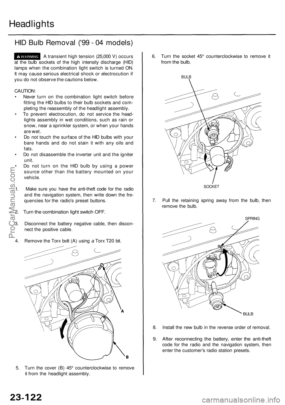
4 . Remov e th e Tor x bol t (A ) usin g a Tor x T2 0 bit .
5 . Tur n th e cove r (B ) 45 ° counterclockwis e t o remov e
i t fro m th e headligh t assembly . 8
. Instal l th e ne w bul b in th e revers e orde r o f removal .
9. Afte r reconnectin g th e battery , ente r th e anti-thef t
code fo r th e radi o an d th e navigatio n system , the n
ente r th e customer' s radi o statio n presets .
BULB
SPRIN G
6. Tur n th e socke t 45 ° counterclockwis e t o remov e i t
fro m th e bulb .
BULB
7. Pul l th e retainin g sprin g awa y fro m th e bulb , the n
remov e th e bulb .
SOCKE T
ProCarManuals.com
Page 1567 of 1954
Stereo Soun d Syste m
Audio Uni t Remova l
SRS component s ar e locate d i n thi s area . Revie w th e
SR S componen t locations , precautions , an d procedure s
i n th e SR S ( sectio n 24 ) befor e performin g repair s o r
service .
With navigatio n system :
1 . Mak e sur e yo u hav e th e anti-thef t cod e fo r th e radi o
an d th e navigatio n system , the n writ e dow n th e fre -
quencie s fo r th e radio' s prese t buttons .
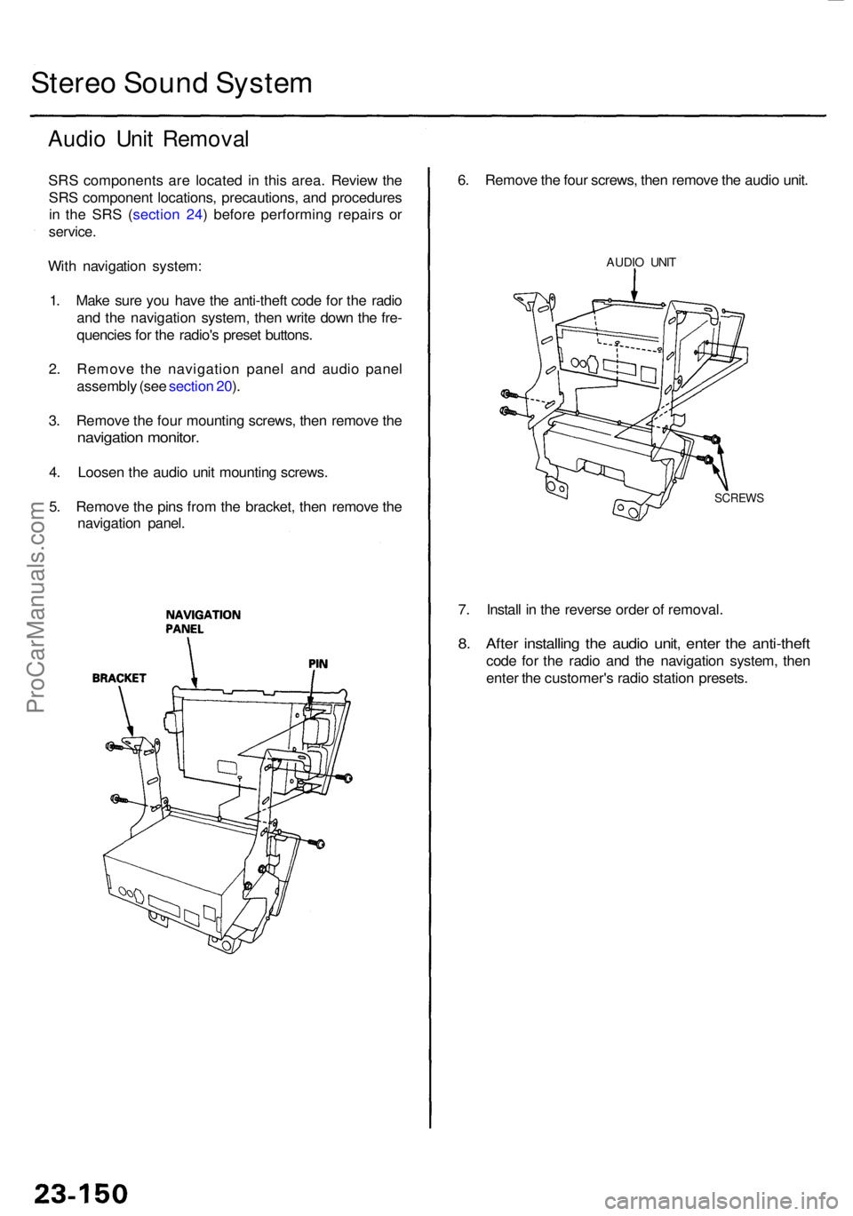
2 . Remov e th e navigatio n pane l an d audi o pane l
assembl y (se e sectio n 20 ).
3 . Remov e th e fou r mountin g screws , the n remov e th e
navigatio n monitor .
4. Loose n th e audi o uni t mountin g screws .
5 . Remov e th e pin s fro m th e bracket , the n remov e th e
navigatio n panel .
7. Instal l i n th e revers e orde r o f removal .
8. Afte r installin g th e audi o unit , ente r th e anti-thef t
code fo r th e radi o an d th e navigatio n system , the n
ente r th e customer' s radi o statio n presets .
6
. Remov e th e fou r screws , the n remov e th e audi o unit .
AUDI O UNI T
SCREW S
ProCarManuals.com
Page 1568 of 1954
3. Remov e th e seve n (o r eight ) mountin g screws , the n
remov e th e audi o unit .
4. Instal l i n th e revers e orde r o f removal .
5 . Afte r installin g th e audi o unit , ente r th e anti-thef t
cod e fo r th e radio , the n ente r th e customer' s radi o
statio n presets .
Withou
t navigatio n system :
1 . Mak e sur e yo u hav e th e anti-thef t cod e fo r th e
radio , the n writ e dow n th e frequencie s fo r th e
radio' s prese t buttons .
2 . Remov e th e automati c climat e contro l pane l an d
audi o pane l assembl y (se e sectio n 20 ).
SCRE W
AUDIOUNIT
BRACKE T
BOLT
ProCarManuals.com
Page 1571 of 1954
Stereo Soun d Syste m
Radio Remot e Switc h Tes t
SRS component s ar e locate d i n thi s area . Revie w th e
SR S componen t locations , precautions , an d procedure s
i n th e SR S (sectio n 24 ) befor e performin g repair s o r
service .
1. Remov e th e switc h cove r fro m th e radi o remot e
switch.
RADIO REMOT E SWITC H
SWITC H COVE R
2P CONNECTO R
2. Remov e th e radi o remot e switc h fro m th e steerin g
whee l b y removin g th e tw o screws , an d disconnec t
th e 2 P connector . 3
. Remov e th e remot e switc h fro m th e steerin g whee l
(se e sectio n 17 ).
4 . Measur e resistanc e betwee n th e No . 1 an d No . 2
terminal s i n eac h switc h positio n accordin g t o th e
table .
Positio nResistanc e
Approx. 10 0
Approx . 35 0
Approx
. 77 0
Approx
. 3. 6
OF F
AUDIO/C H
(SEEK)
(VOL. UP)
(VOL . DOWN )
ProCarManuals.com