1996 ACURA RL KA9 radio
[x] Cancel search: radioPage 1366 of 1954
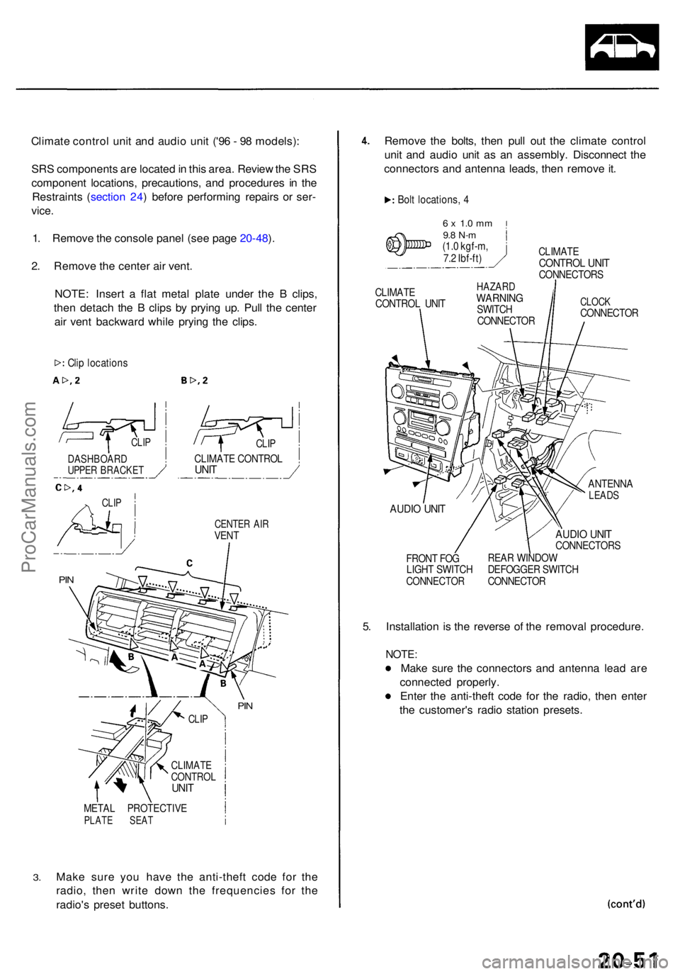
Climate contro l uni t an d audi o uni t ('9 6 - 9 8 models) :
SR S component s ar e locate d in thi s area . Revie w th e SR S
componen t locations , precautions , an d procedure s i n th e
Restraint s ( sectio n 24 ) befor e performin g repair s o r ser -
vice .
1. Remov e th e consol e pane l (se e pag e 20-48 ).
2 . Remov e th e cente r ai r vent .
NOTE : Inser t a fla t meta l plat e unde r th e B clips ,
the n detac h th e B clip s b y pryin g up . Pul l th e cente r
ai r ven t backwar d whil e pryin g th e clips .
CENTE R AI RVEN T
3.
META L PROTECTIV EPLATE SEA T
Make sur e yo u hav e th e anti-thef t cod e fo r th e
radio , the n writ e dow n th e frequencie s fo r th e
radio' s prese t buttons. Remov
e th e bolts , the n pul l ou t th e climat e contro l
uni t an d audi o uni t a s a n assembly . Disconnec t th e
connector s an d antenn a leads , the n remov e it .
Bol t locations , 4
6 x 1. 0 m m9.8 N- m(1.0 kgf-m ,
7. 2 Ibf-ft ) CLIMAT
E
CONTRO L UNI TCONNECTOR S
CLIMAT E
CONTRO L UNI THAZAR DWARNIN GSWITCH
CONNECTO RCLOCKCONNECTO R
AUDIO UNI T
FRON T FO G
LIGH T SWITC H
CONNECTO R
ANTENNALEADS
AUDIO UNI TCONNECTOR S
REA R WINDO W
DEFOGGE R SWITC H
CONNECTO R
5. Installatio n i s th e revers e o f th e remova l procedure .
NOTE:
Make sur e th e connector s an d antenn a lea d ar e
connecte d properly .
Ente r th e anti-thef t cod e fo r th e radio , the n ente r
th e customer' s radi o statio n presets .
Clip location s
CLIPCLIP
CLIMAT E CONTRO LUNITDASHBOAR DUPPER BRACKE T
CLIP
PIN
PIN
CLI P
CLIMAT ECONTRO LUNIT
ProCarManuals.com
Page 1367 of 1954
Dashboard
Componen t Removal/Installatio n (cont'd )
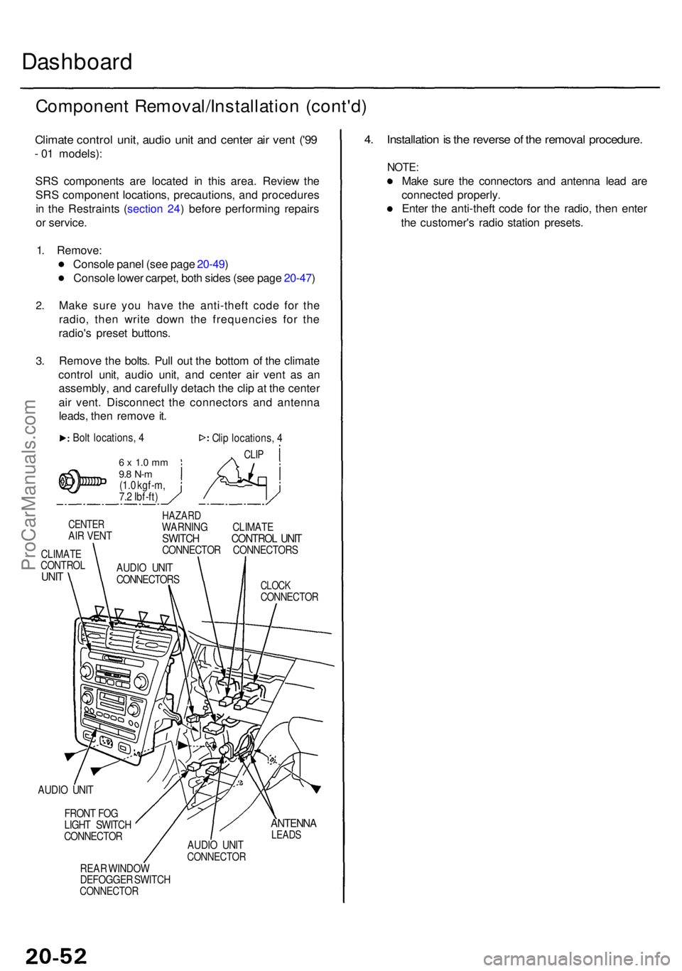
Climate contro l unit , audi o uni t an d cente r ai r ven t ('9 9
- 0 1 models) :
SR S component s ar e locate d i n thi s area . Revie w th e
SR S componen t locations , precautions , an d procedure s
i n th e Restraint s ( sectio n 24 ) befor e performin g repair s
o r service .
1 . Remove :
Consol e pane l (se e pag e 20-49 )
Consol e lowe r carpet , bot h side s (se e pag e 20-47 )
2.
3.
Mak e sur e yo u hav e th e anti-thef t cod e fo r th e
radio , the n writ e dow n th e frequencie s fo r th e
radio' s prese t buttons .
Remov e th e bolts . Pul l ou t th e botto m o f th e climat e
contro l unit , audi o unit , an d cente r ai r ven t a s a n
assembly , an d carefull y detac h th e cli p a t th e cente r
ai r vent . Disconnec t th e connector s an d antenn a
leads , the n remov e it .
Bol t locations , 4
6 x 1. 0 m m9.8 N- m(1.0 kgf-m ,
7. 2 Ibf-ft ) Cli
p locations , 4
CLI P
CENTE RAIR VEN T
CLIMAT ECONTRO LUNIT
HAZAR DWARNIN G CLIMAT ESWITCH CONTRO L UNI TCONNECTO R CONNECTOR S
CLOCKCONNECTO R
AUDIO UNI T
FRON T FO G
LIGH T SWITC H
CONNECTO R
REA R WINDO W
DEFOGGE R SWITC H
CONNECTO R
ANTENNALEADSAUDIO UNI TCONNECTO R
4. Installatio n is th e revers e o f th e remova l procedure .
NOTE:
Make sur e th e connector s an d antenn a lea d ar e
connecte d properly .
Ente r th e anti-thef t cod e fo r th e radio , the n ente r
th e customer' s radi o statio n presets .
AUDIO UNI T
CONNECTOR S
ProCarManuals.com
Page 1370 of 1954
Removal
SRS component s ar e locate d in thi s area . Revie w th e SR S
componen t locations , precautions , an d procedure s i n th e
Restraint s ( sectio n 24 ) befor e preformin g repair s o r ser -
vice .
NOTE :
• A n assistan t i s helpfu l whe n removin g an d installin g
th e dashboard .
• Tak e car e no t t o scratc h th e dashboard , body , an d
relate d parts .
1 . Mak e sur e yo u hav e th e anti-thef t cod e fo r th e
radio , the n writ e dow n th e frequencie s fo r th e
radio' s prese t buttons .
2 . Disconnec t th e negativ e cabl e fro m th e battery .
3 . Remove :
• Consol e pane l an d rea r console , '9 6 - 9 8 model s
(se e pag e 20-48 )
• Consol e pane l an d rea r console , '9 9 - 0 1 model s
(se e pag e 20-49 )
• Cente r ai r vent , '9 6 - 9 8 model s (se e pag e 20-51 )
• Climat e contro l uni t an d audi o unit , '9 6 - 9 8 model s
(se e pag e 20-51 )
• Climat e contro l unit , audi o unit , an d cente r ai r vent ,
'99 - 0 1 model s (se e pag e 20-52 )
• Dashboar d lowe r cove r (passenger's) , glov e bo x
an d glov e bo x bac k cove r (se e pag e 20-53 )
• Consol e lowe r carpe t (se e pag e 20-47 )
• Dashboar d lowe r cove r (driver's ) (se e pag e 20-50 )
• Kic k pane l (se e pag e 20-43 )
4 . Lowe r th e steerin g colum n (se e sectio n 17 ).
T o avoi d accidenta l deploymen t an d
possibl e injury / alway s disconnec t th e driver' s airba g
connecto r befor e lowerin g th e steerin g colum n (se e
sectio n 24 ).
NOTE : T o preven t damag e to th e steerin g column , wra p it
wit h a sho p towel .
5. Remove the front passenger's airbag (see
section 24 ).
T o avoi d accidenta l deploymen t an d
possibl e injury , alway s disconnec t th e fron t passen -
ger' s airba g connecto r whe n th e SR S mai n harnes s
i s disconnecte d (se e sectio n 24 ).
Dashboar d
ProCarManuals.com
Page 1371 of 1954
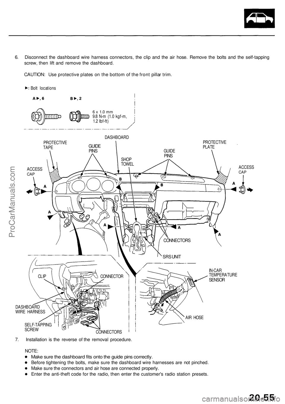
6. Disconnec t th e dashboar d wir e harnes s connectors , th e cli p an d th e ai r hose . Remov e th e bolt s an d th e self-tappin g
screw , the n lif t an d remov e th e dashboard .
CAUTION : Us e protectiv e plate s o n th e botto m of th e fron t pilla r trim .
Bolt location s
PROTECTIV E
TAPE
ACCES SCAP
6 x 1. 0 m m9.8 N- m (1. 0 kgf-m ,
1. 2 Ibf-ft )
DASHBOAR D
GUIDEPINS
PROTECTIV E
PLAT E
ACCESS
CAP
IN-CA R
TEMPERATUR E
SENSOR
7. Installatio n i s th e revers e o f th e remova l procedure .
NOTE:
Make sur e th e dashboar d fit s ont o th e guid e pin s correctly .
Before tightenin g th e bolts , mak e sur e th e dashboar d wir e harnesse s ar e no t pinched .
Mak e sur e th e connector s an d ai r hos e ar e connecte d properly .
Ente r th e anti-thef t cod e fo r th e radio , the n ente r th e customer' s radi o statio n presets .
SELF-TAPPIN G
SCRE W
CONNECTORS AI
R HOS E
CONNECTO
R
CLIP
DASHBOAR D
WIR E HARNES S
SRS UNI T
CONNECTOR S
GUIDEPINSSHO P
TOWE L
ProCarManuals.com
Page 1373 of 1954
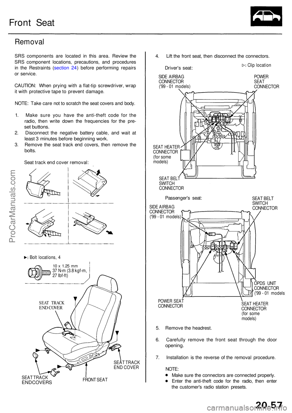
Front Sea t
Remova l
SRS component s ar e locate d i n thi s area . Revie w th e
SR S componen t locations , precautions , an d procedure s
i n th e Restraint s ( sectio n 24 ) befor e performin g repair s
o r service .
CAUTION : Whe n pryin g wit h a flat-ti p screwdriver , wra p
i t wit h protectiv e tap e t o preven t damage .
NOTE : Tak e car e no t t o scratc h th e sea t cover s an d body .
1 . Mak e sur e yo u hav e th e anti-thef t cod e fo r th e
radio , the n writ e dow n th e frequencie s fo r th e pre -
set buttons .
2. Disconnec t th e negativ e batter y cable , an d wai t a t
leas t 3 minute s befor e beginnin g work .
3. Remov e th e sea t trac k en d covers , the n remov e th e
bolts .
Seat trac k en d cove r removal :
Bolt locations , 4
1 0 x 1.2 5 mm37 N- m (3. 8 kgf-m ,
2 7 Ibf-ft )
SEA T TRAC K
END COVE R
SEAT TRAC K
EN D COVE R
SEA T TRAC K
END COVER S FRON T SEA T
4. Lif t th e fron t seat , the n disconnec t th e connectors .
Driver' s seat :
SIDE AIRBA G
CONNECTO R
('9 9 - 0 1 models )
SEAT HEATE RCONNECTO R(for som e
models )
SEAT BEL TSWITC HCONNECTO R
Passenger's seat :
SIDE AIRBA GCONNECTO R('99 - 0 1 models ) Cli
p locatio n
POWERSEATCONNECTO R
SEA T BEL T
SWITC H
CONNECTO R
POWER SEA TCONNECTO R
5. Remov e th e headrest .
6 . Carefull y remov e th e fron t sea t throug h th e doo r
opening .
7. Installatio n i s th e revers e o f th e remova l procedure .
NOTE:
Make sur e th e connector s ar e connecte d properly .
Ente r th e anti-thef t cod e fo r th e radio , the n ente r
th e customer' s radi o statio n presets .
SEAT HEATE RCONNECTO R
(fo r som e
models )
OPD
S UNI T
CONNECTO R
('9 9 - 0 1 model s
ProCarManuals.com
Page 1484 of 1954
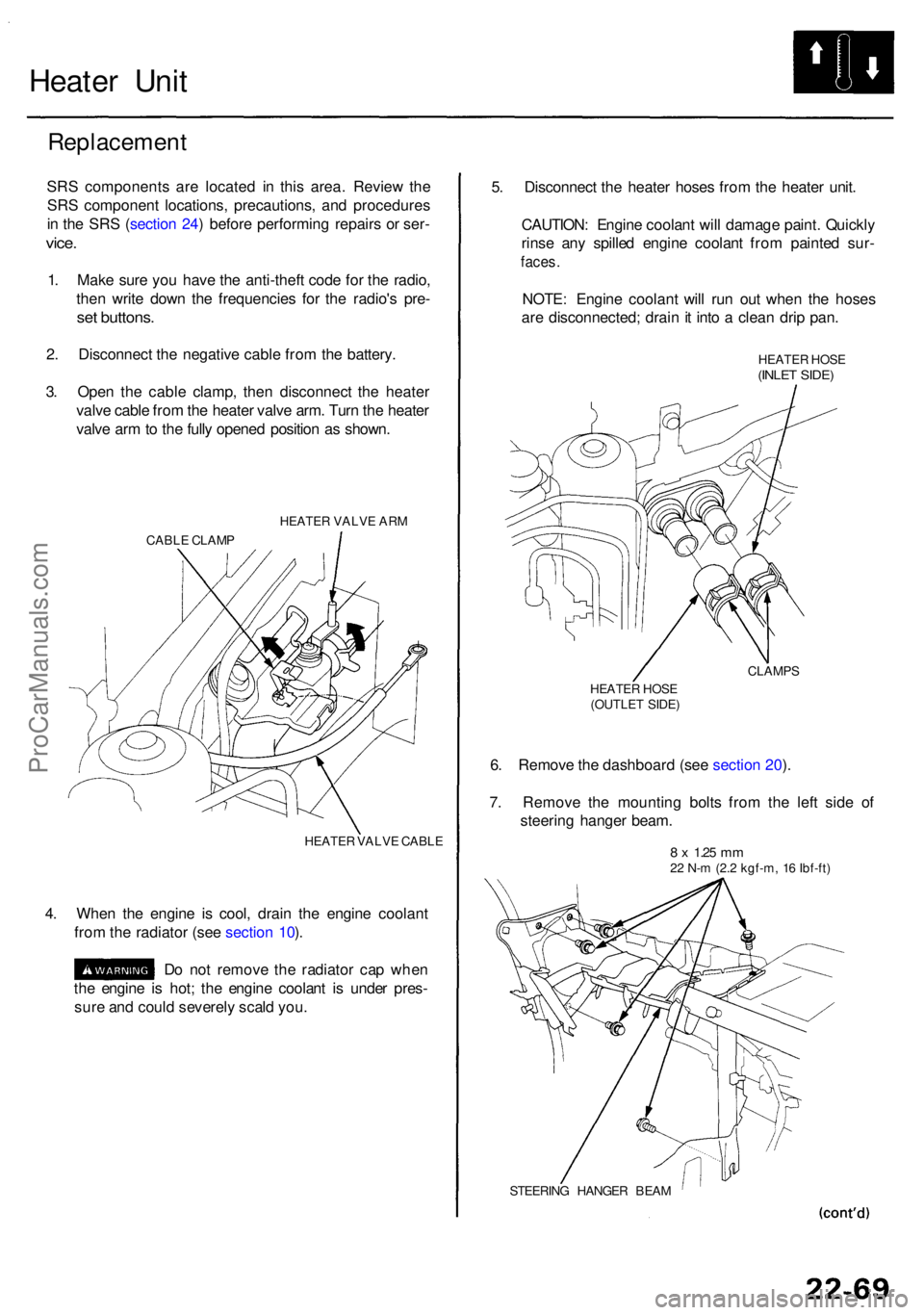
Heater Uni t
Replacemen t
SRS component s ar e locate d i n thi s area . Revie w th e
SR S componen t locations , precautions , an d procedure s
i n th e SR S (sectio n 24 ) befor e performin g repair s o r ser -
vice.
1. Mak e sur e yo u hav e th e anti-thef t cod e fo r th e radio ,
the n writ e dow n th e frequencie s fo r th e radio' s pre -
set buttons .
2. Disconnec t th e negativ e cabl e fro m th e battery .
3 . Ope n th e cabl e clamp , the n disconnec t th e heate r
valv e cabl e fro m th e heate r valv e arm . Tur n th e heate r
valv e ar m to th e full y opene d positio n a s shown .
HEATE R VALV E AR M
CABL E CLAM P
HEATER VALV E CABL E
4. Whe n th e engin e i s cool , drai n th e engin e coolan t
fro m th e radiato r (se e sectio n 10 ).
D o no t remov e th e radiato r ca p whe n
th e engin e i s hot ; th e engin e coolan t i s unde r pres -
sur e an d coul d severel y scal d you . 5
. Disconnec t th e heate r hose s fro m th e heate r unit .
CAUTION : Engin e coolan t wil l damag e paint . Quickl y
rins e an y spille d engin e coolan t fro m painte d sur -
faces .
NOTE : Engin e coolan t wil l ru n ou t whe n th e hose s
ar e disconnected ; drai n it int o a clea n dri p pan .
HEATE R HOS E(INLE T SIDE )
CLAMP S
HEATE R HOS E
(OUTLE T SIDE )
6. Remov e th e dashboar d (se e sectio n 20 ).
7 . Remov e th e mountin g bolt s fro m th e lef t sid e o f
steerin g hange r beam .
8 x 1.2 5 mm22 N- m (2. 2 kgf-m , 1 6 Ibf-ft )
STEERIN G HANGE R BEA M
ProCarManuals.com
Page 1485 of 1954
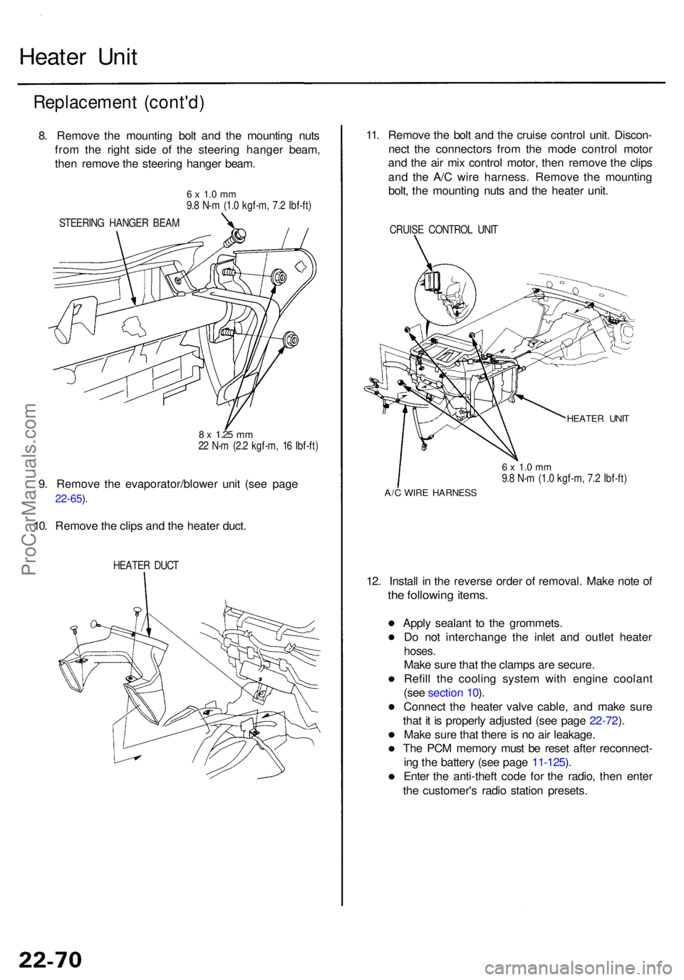
Heater Uni t
Replacemen t (cont'd )
8. Remov e th e mountin g bol t an d th e mountin g nut s
fro m th e righ t sid e o f th e steerin g hange r beam ,
the n remov e th e steerin g hange r beam .
6 x 1. 0 m m9.8 N- m (1. 0 kgf-m , 7. 2 Ibf-ft )
STEERIN G HANGE R BEA M
8 x 1.2 5 mm22 N- m (2. 2 kgf-m , 1 6 Ibf-ft )
9. Remov e th e evaporator/blowe r uni t (se e pag e
22-65 ).
10. Remov e th e clip s an d th e heate r duct .
HEATE R DUC T
11. Remov e th e bol t an d th e cruis e contro l unit . Discon -
nec t th e connector s fro m th e mod e contro l moto r
an d th e ai r mi x contro l motor , the n remov e th e clip s
an d th e A/ C wir e harness . Remov e th e mountin g
bolt , th e mountin g nut s an d th e heate r unit .
CRUIS E CONTRO L UNI T
HEATE R UNI T
6 x 1. 0 m m9.8 N- m (1. 0 kgf-m , 7. 2 Ibf-ft )
A/C WIR E HARNES S
12. Instal l i n th e revers e orde r o f removal . Mak e not e o f
the followin g items .
Apply sealan t t o th e grommets .
D o no t interchang e th e inle t an d outle t heate r
hoses.
Make sur e tha t th e clamp s ar e secure .
Refil l th e coolin g syste m wit h engin e coolan t
(se e sectio n 10 ).
Connec t th e heate r valv e cable , an d mak e sur e
tha t i t i s properl y adjuste d (se e pag e 22-72 ).
Mak e sur e tha t ther e is n o ai r leakage .
Th e PC M memor y mus t b e rese t afte r reconnect -
in g th e batter y (se e pag e 11-125 ).
Ente r th e anti-thef t cod e fo r th e radio , the n ente r
th e customer' s radi o statio n presets .
ProCarManuals.com
Page 1494 of 1954
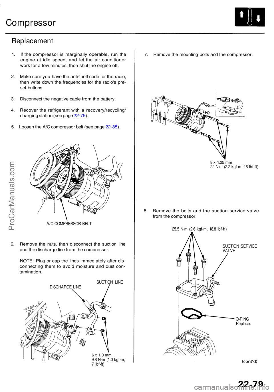
Compressor
Replacemen t
1. I f th e compresso r i s marginall y operable , ru n th e
engin e a t idl e speed , an d le t th e ai r conditione r
wor k fo r a fe w minutes , the n shu t th e engine off.
2 . Mak e sur e yo u hav e th e anti-thef t cod e fo r th e radio ,
the n writ e dow n th e frequencie s fo r th e radio' s pre -
se t buttons .
3 . Disconnec t th e negativ e cabl e fro m th e battery .
4 . Recove r th e refrigeran t wit h a recovery/recycling /
chargin g statio n (se e pag e 22-75 ).
5 . Loose n th e A/ C compresso r bel t (se e pag e 22-85 ).
A/ C COMPRESSO R BEL T
6. Remov e th e nuts , the n disconnec t th e suctio n lin e
an d th e discharg e lin e fro m th e compressor .
NOTE : Plu g o r ca p th e line s immediatel y afte r dis -
connectin g the m to avoi d moistur e an d dus t con -
tamination .
SUCTION LIN E
DISCHARG E LIN E
6 x 1. 0 m m9.8 N- m (1. 0 kgf-m ,
7 Ibf-ft )
7. Remov e th e mountin g bolt s an d th e compressor .
8 x 1.2 5 mm22 N- m (2. 2 kgf-m , 1 6 Ibf-ft )
8. Remov e th e bolt s an d th e suctio n servic e valv e
fro m th e compressor .
25.5 N- m (2. 6 kgf-m , 18. 8 Ibf-ft )
SUCTIO N SERVIC E
VALV E
O-RIN G
Replace .
ProCarManuals.com