Page 1463 of 1954
Troubleshooting
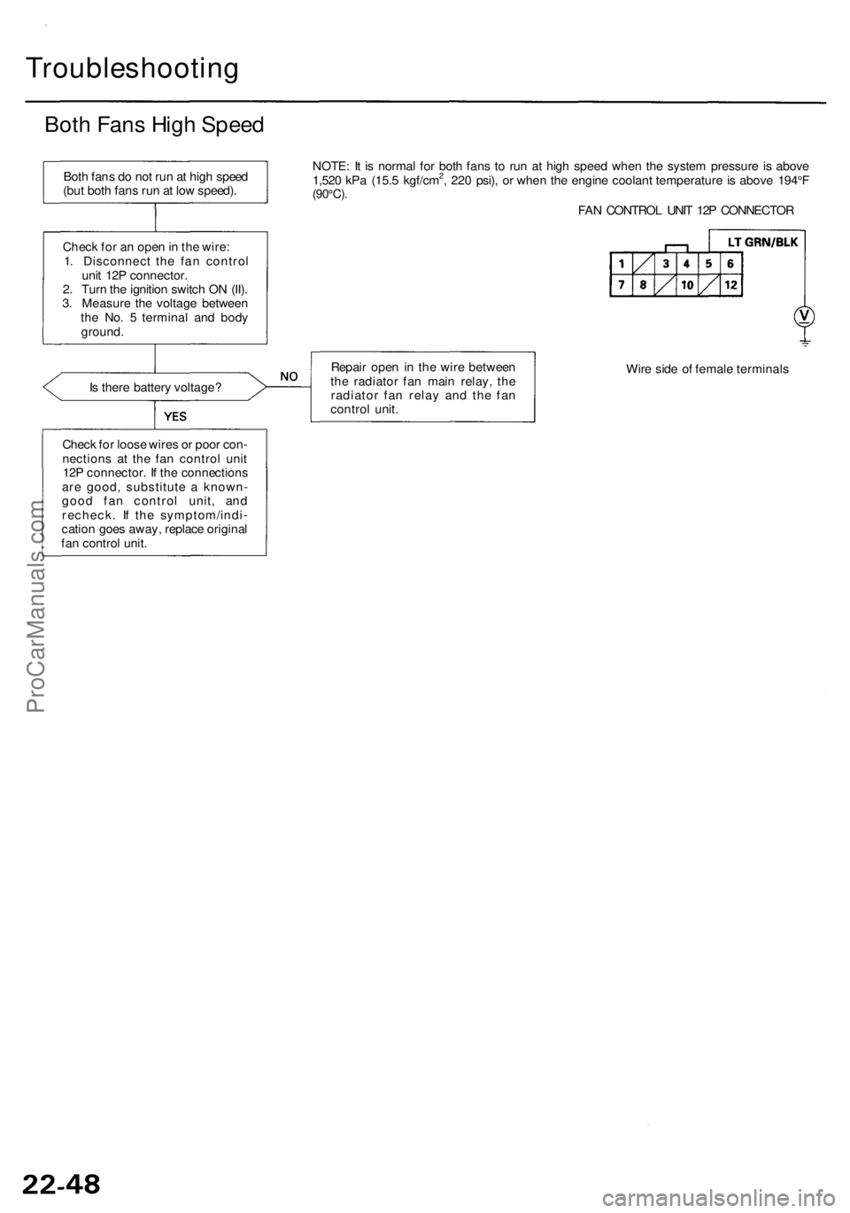
Both Fan s Hig h Spee d
Is ther e batter y voltage ?
Chec k fo r loos e wire s o r poo r con -
nection s a t th e fa n contro l uni t
12 P connector . I f th e connection s
ar e good , substitut e a known -
goo d fa n contro l unit , an d
recheck . I f th e symptom/indi -
catio n goe s away , replac e origina l
fa n contro l unit . NOTE
: I t i s norma l fo r bot h fan s t o ru n a t hig h spee d whe n th e syste m pressur e i s abov e
1,52 0 kP a (15. 5 kgf/cm
2, 22 0 psi) , o r whe n th e engin e coolan t temperatur e is abov e 194° F(90°C) .
FAN CONTRO L UNI T 12 P CONNECTO R
Repai r ope n in th e wir e betwee n
th e radiato r fa n mai n relay , th e
radiato r fa n rela y an d th e fa n
contro l unit . Wir
e sid e o f femal e terminal s
Bot
h fan s d o no t ru n a t hig h spee d
(bu t bot h fan s ru n a t lo w speed) .
Chec k fo r a n ope n in th e wire :
1 . Disconnec t th e fa n contro l
uni t 12 P connector .
2 . Tur n th e ignitio n switc h O N (II) .
3 . Measur e th e voltag e betwee n
th e No . 5 termina l an d bod y
ground .
ProCarManuals.com
Page 1464 of 1954
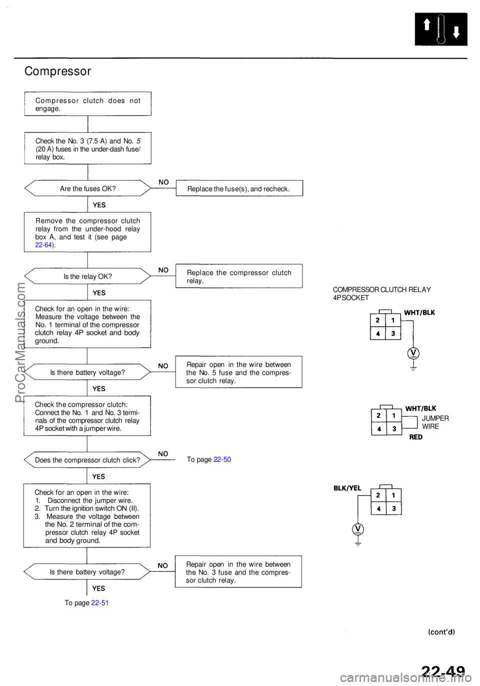
Compressor
Compresso r clutc h doe s no t
engage .
Chec k th e No . 3 (7. 5 A ) an d No . 5
(2 0 A ) fuse s in th e under-das h fuse /
rela y box .
Ar e th e fuse s OK ?
Remov e th e compresso r clutc h
rela y fro m th e under-hoo d rela y
bo x A , an d tes t i t (se e pag e
22-64 ).
Is th e rela y OK ?
Chec k fo r a n ope n in th e wire :
Measur e th e voltag e betwee n th e
No. 1 termina l o f th e compresso rclutch rela y 4 P socke t an d bod yground .
Is ther e batter y voltage ?
Chec k th e compresso r clutch :
Connec t th e No . 1 an d No . 3 termi -
nal s o f th e compresso r clutc h rela y
4P socke t wit h a jumpe r wire .
Does th e compresso r clutc h click ?
Chec k fo r a n ope n in th e wire :
1 . Disconnec t th e jumpe r wire .
2. Tur n th e ignitio n switc h O N (II) .3. Measur e th e voltag e betwee nthe No . 2 termina l o f th e com -presso r clutc h rela y 4 P socke tand bod y ground .
Is ther e batter y voltage ?
T o pag e 22-5 1 Replac
e th e fuse(s) , an d recheck .
Replac e th e compresso r clutc h
relay .
COMPRESSOR CLUTC H RELA Y
4 P SOCKE T
Repai r ope n i n th e wir e betwee n
th e No . 5 fus e an d th e compres -
so r clutc h relay .
T o pag e 22-5 0
Repai r ope n i n th e wir e betwee n
th e No . 3 fus e an d th e compres -
so r clutc h relay . JUMPE
R
WIRE
ProCarManuals.com
Page 1466 of 1954
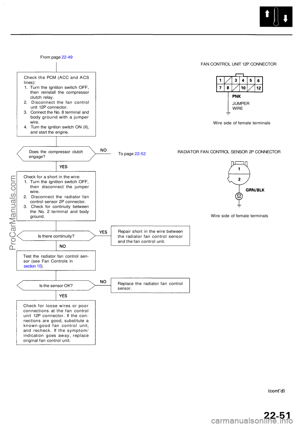
From pag e 22-4 9
Chec k th e PC M (AC C an d AC S
lines) :1. Tur n th e ignitio n switc h OFF ,then reinstal l th e compresso r
clutc h relay .
2 . Disconnec t th e fa n contro l
uni t 12 P connector .
3 . Connec t th e No . 8 termina l an d
bod y groun d wit h a jumpe rwire.
4 . Tur n th e ignitio n switc h O N (II) ,
an d star t th e engine .
Doe s th e compresso r clutc h
engage ?
Is ther e continuity ?
Test th e radiato r fa n contro l sen -
so r (se e Fa n Control s i n
section 10 ).
Is th e senso r OK ?
Chec k fo r loos e wire s o r poo r
connection s a t th e fa n contro l
uni t 12 P connector . I f th e con -
nection s ar e good , substitut e a
known-goo d fa n contro l unit ,
an d recheck . I f th e symptom /
indicatio n goe s away , replac e
origina l fa n contro l unit . FA
N CONTRO L UNI T 12 P CONNECTO R
T o pag e 22-5 2 Wir
e sid e o f femal e terminal s
RADIATO R FA N CONTRO L SENSO R 2 P CONNECTO R
Wir e sid e o f femal e terminal s
Repai r shor t i n th e wir e betwee n
th e radiato r fa n contro l senso r
an d th e fa n contro l unit .
Replac e th e radiato r fa n contro lsensor.
Check fo r a shor t i n th e wire :1. Tur n th e ignitio n switc h OFF ,then disconnec t th e jumpe rwire.2. Disconnec t th e radiato r fa n
contro l senso r 2 P connector .
3 . Chec k fo r continuit y betwee n
th e No . 2 termina l an d bod y
ground . JUMPE
R
WIRE
ProCarManuals.com
Page 1473 of 1954
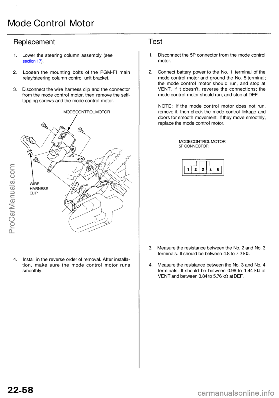
Mode Contro l Moto r
Replacemen t Tes
t
1. Lowe r th e steerin g colum n assembl y (se e
section 17 ).
2 . Loose n th e mountin g bolt s of the PGM-F I mai n
relay/steerin g colum n contro l uni t bracket .
3 . Disconnec t th e wir e harnes s cli p an d th e connecto r
fro m th e mod e contro l motor , the n remov e th e self -
tappin g screw s an d th e mod e contro l motor .
MODE CONTRO L MOTO R
WIREHARNES SCLIP
4. Instal l i n th e revers e orde r o f removal . Afte r installa -
tion , mak e sur e th e mod e contro l moto r run s
smoothly . 1
. Disconnec t th e 5 P connecto r fro m th e mod e contro l
motor .
2 . Connec t batter y powe r t o th e No . 1 termina l o f th e
mod e contro l moto r an d groun d th e No . 5 terminal ;
th e mod e contro l moto r shoul d run , an d sto p a t
VENT . I f i t doesn't , revers e th e connections ; th e
mod e contro l moto r shoul d run , an d sto p a t DEF .
NOTE : I f th e mod e contro l moto r doe s no t run ,
remov e it , the n chec k th e mod e contro l linkag e an d
door s fo r smoot h movement . I f the y mov e smoothly ,
replac e th e mod e contro l motor .
MODE CONTRO L MOTO R5P CONNECTO R
3. Measur e th e resistanc e betwee n th e No . 2 an d No . 3
terminals . I t shoul d b e betwee n 4. 8 to 7. 2 k .
4 . Measur e th e resistanc e betwee n th e No . 3 an d No . 4
terminals . I t shoul d b e betwee n 0.9 6 t o 1.4 4 k a t
VEN T an d betwee n 3.8 4 to 5.7 6 k a t DEF .
ProCarManuals.com
Page 1479 of 1954
Relays
Test
There should be continuity between the No. 1 and No. 3
terminals when power and ground are connected to the
No. 2 and No. 4 terminals, and there should be no conti-
nuity when power is disconnected.
Radiator fan relay
Condenser fan relay
Compressor clutch relay
Blower motor relay
Blower motor high relay
There should be continuity between the No. 4 and No. 5
terminals when power and ground are connected to the
No. 1 and No. 3 terminals, and there should be continu-
ity between the No. 2 and No. 5 terminals when power
is disconnected.
Radiator fan main relayProCarManuals.com
Page 1480 of 1954
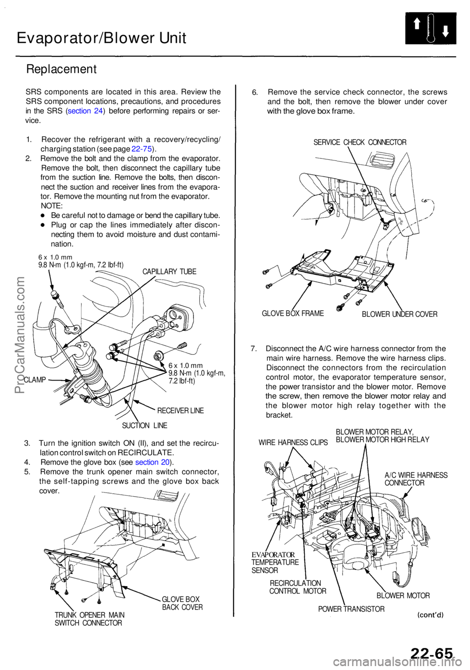
Evaporator/Blower Uni t
Replacemen t
SRS component s ar e locate d i n thi s area . Revie w th e
SR S componen t locations , precautions , an d procedure s
i n th e SR S (sectio n 24 ) befor e performin g repair s o r ser -
vice .
1 . Recove r th e refrigeran t wit h a recovery/recycling /
chargin g statio n (se e pag e 22-75 ).
2 . Remov e th e bol t an d th e clam p fro m th e evaporator .
Remov e th e bolt , the n disconnec t th e capillar y tub e
fro m th e suctio n line . Remov e th e bolts , the n discon -
nec t th e suctio n an d receive r line s fro m th e evapora -
tor . Remov e th e mountin g nu t fro m th e evaporator .
NOTE:
Be carefu l no t t o damag e o r ben d th e capillar y tube .
Plu g o r ca p th e line s immediatel y afte r discon -
nectin g the m to avoi d moistur e an d dus t contami -
nation .
6 x 1. 0 m m9.8 N- m (1. 0 kgf-m , 7. 2 Ibf-ft )
CAPILLAR Y TUB E
CLAM P
6 x 1. 0 m m9.8 N- m (1. 0 kgf-m ,
7. 2 Ibf-ft )
RECEIVE R LIN E
SUCTIO N LIN E
3. Tur n th e ignitio n switc h O N (II) , an d se t th e recircu -
latio n contro l switc h o n RECIRCULATE .
4 . Remov e th e glov e bo x (se e sectio n 20 ).
5 . Remov e th e trun k opene r mai n switc h connector ,
th e self-tappin g screw s an d th e glov e bo x bac k
cover .
GLOV E BO XBAC K COVE RTRUNK OPENE R MAI N
SWITC H CONNECTO R
6.Remov e th e servic e chec k connector , th e screw s
an d th e bolt , the n remov e th e blowe r unde r cove r
with th e glov e bo x frame .
SERVIC E CHEC K CONNECTO R
GLOV E BO X FRAM E
BLOWER UNDE R COVE R
7. Disconnec t th e A/ C wir e harnes s connecto r fro m th e
mai n wir e harness . Remov e th e wir e harnes s clips .
Disconnec t th e connector s fro m th e recirculatio n
contro l motor , th e evaporato r temperatur e sensor ,
th e powe r transisto r an d th e blowe r motor . Remov e
the screw , the n remov e th e blowe r moto r rela y an d
the blowe r moto r hig h rela y togethe r wit h th e
bracket .
WIRE HARNES S CLIP SBLOWE
R MOTO R RELAY ,
BLOWE R MOTO R HIG H RELA Y
A/ C WIR E HARNES S
CONNECTO R
EVAPORATO RTEMPERATUR E
SENSO R
RECIRCULATIO N
CONTRO L MOTO R
BLOWER MOTO R
POWE R TRANSISTO R
ProCarManuals.com
Page 1510 of 1954
Relay an d Contro l Uni t Location s
Engine Compartmen t
TCS FAIL-SAF E RELA Y('96-99 models )
• FRON T SEA T HEATE R
RELA Y ('9 8 model )
• ACCESSOR Y POWE R
SOCKE T RELA Y
('9 9-0 1 models )
UNDER-HOO D RELA Y
BOX C
RADIATO R FA NRELA Y
VSA MODULATO R UNI T('00 - 01 models )
• POWE R WINDO W
MASTE R SWITC H
RELAY('96-9 7 models )• TAILLIGH T RELA Y
('9 9-0 1 models )WINDSHIEL
D WIPE R
MOTO R RELA Y
- AB S REA R FAIL-SAF E
RELAY('96-9 7 models )• HOR N RELA Y
('9 8-0 1 models )
FRON T FO G LIGH T
RELA Y
• AB S FRON T FAIL-SAF E
RELA Y ('96-9 7 models )
• AB S FAIL-SAF E RELA Y
('98-99 models )
GAUGE RELA Y
A/ T REVERS ERELAY
REAR WINDO W
DEFOGGE R RELA Y
WINDSHIEL D WIPE R
INTERMITTEN TRELAYRADIATO R FA N
MAI N RELA Y CONDENSE
R FA NRELA YA/C COMPRESSO R
CLUTC H RELA Y
•
LO W BEA M CU T RELA Y
(Canada : '9 6 - 9 8 models )
• SECURIT Y HOR N RELA Y
(USA: '99-0 1 models )
• LO W BEA M CU T RELA Y
(Canada : '0 0-0 1 models )
UNDER-HOO D RELA Y
BOX A
ProCarManuals.com
Page 1511 of 1954
IGNITION CONTRO LMODULE (ICM )
UNDER-HOO D RELA YBOX B
DRIVER' S POWE R WINDO W MOTO R RELA Y B('98-0 1 models )• HOR N RELA Y('96-97 models )• POWE R WINDO W MASTE R SWITC H
RELA Y ('98-0 1 models )
CIGARETT E LIGHTE R RELA Y
• FRON T SEA T HEATE R RELA Y
('96-97 models )• DRIVER' S POWE R WINDO W MOTO R RELA Y A
('9 8-0 1 models )
SPAR K PLU G VOLTAG E
DETECTIO N MODUL E
DIMME R RELA Y •
AB S PUM P MOTO R RELA Y
('96-99 models )• VS A FAIL-SAF E RELA Y
('0 0-0 1 models )
• HEADLIGH T RELA Y
('96-98 models )• HEADLIGH T
LO W BEA M RELA Y
('99-01 models )
TAILLIGH T RELA Y
('9 6 - 9 8 models )
• HEADLIGH T HIG H BEA M RELA Y
('9 9-0 1 models )
UNDER-HOO
D
FUSE/RELAYBOX
ProCarManuals.com