1996 ACURA RL KA9 relay
[x] Cancel search: relayPage 1670 of 1954
Rear Windo w Defogge r
Function Tes t
CAUTION : B e carefu l no t t o scratc h o r damag e th e defog -
ge r wire s wit h th e teste r probe .
1. Chec k fo r voltag e betwee n th e positiv e termina l an d
bod y groun d wit h th e ignitio n switc h an d defogge r
switc h ON .
Ther e shoul d b e batter y voltage .
• I f ther e is n o voltage , chec k for :
fault y defogge r relay ,
fault y defogge r switch .
fault y defogge r coil .
a n ope n in th e YEL/BL U wire .
• I f ther e i s batter y voltage , g o t o ste p 2 .
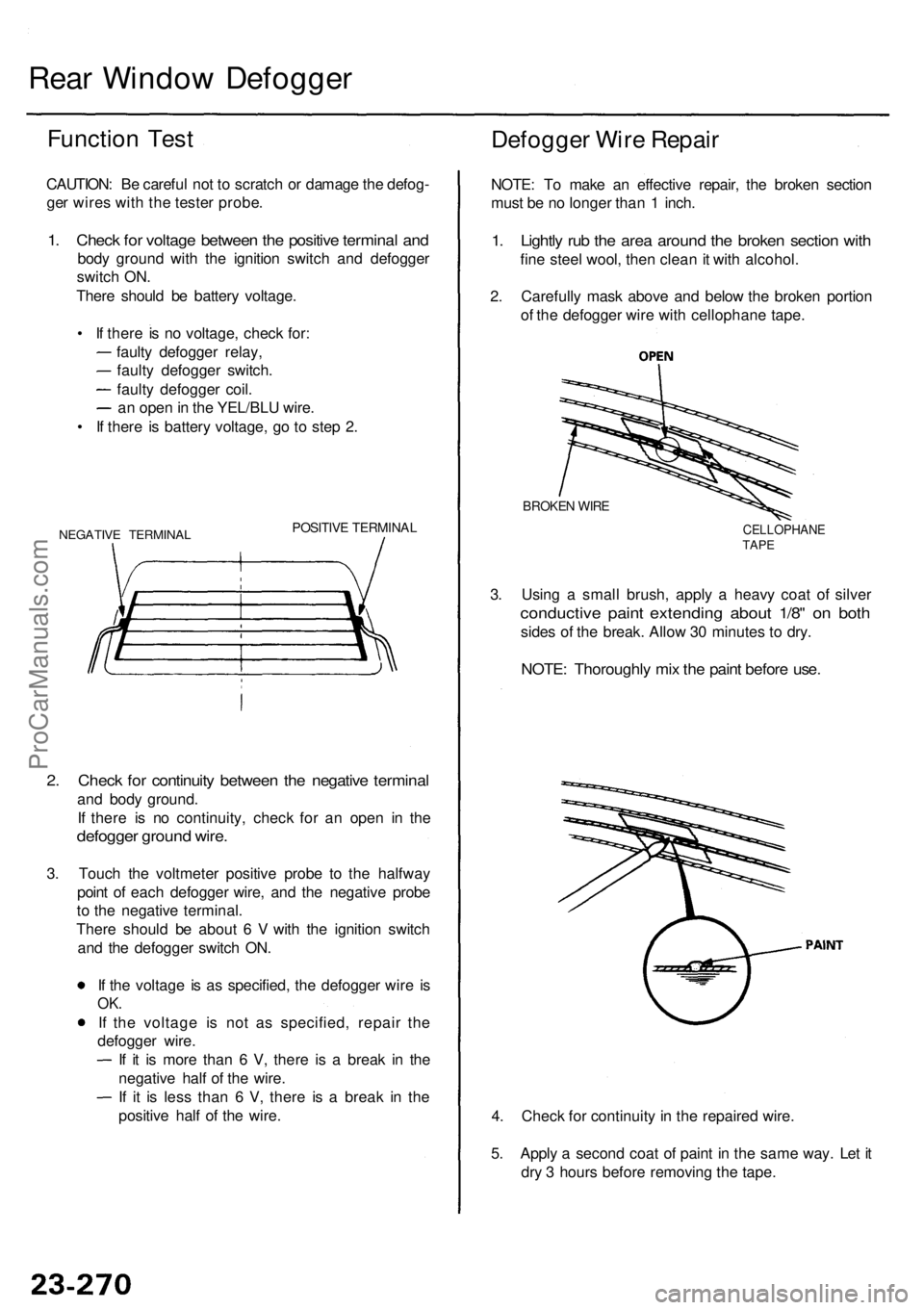
NEGATIV E TERMINA LPOSITIVE TERMINA L
2. Chec k fo r continuit y betwee n th e negativ e termina l
and bod y ground .
I f ther e i s n o continuity , chec k fo r a n ope n i n th e
defogge r groun d wire .
3. Touc h th e voltmete r positiv e prob e t o th e halfwa y
poin t o f eac h defogge r wire , an d th e negativ e prob e
t o th e negativ e terminal .
Ther e shoul d b e abou t 6 V with th e ignitio n switc h
an d th e defogge r switc h ON .
I f th e voltag e i s a s specified , th e defogge r wir e i s
OK .
If th e voltag e i s no t a s specified , repai r th e
defogge r wire .
I f i t i s mor e tha n 6 V , ther e i s a brea k i n th e
negativ e hal f o f th e wire .
I f i t i s les s tha n 6 V , ther e i s a brea k i n th e
positiv e hal f o f th e wire .
Defogge r Wir e Repai r
NOTE: T o mak e a n effectiv e repair , th e broke n sectio n
mus t b e n o longe r tha n 1 inch .
1. Lightl y ru b th e are a aroun d th e broke n sectio n wit h
fine stee l wool , the n clea n it wit h alcohol .
2 . Carefull y mas k abov e an d belo w th e broke n portio n
o f th e defogge r wir e wit h cellophan e tape .
3 . Usin g a smal l brush , appl y a heav y coa t o f silve r
conductiv e pain t extendin g abou t 1/8 " o n bot h
sides o f th e break . Allo w 3 0 minute s t o dry .
BROKE N WIR E
CELLOPHAN ETAPE
NOTE : Thoroughl y mi x th e pain t befor e use .
4. Chec k fo r continuit y in th e repaire d wire .
5 . Appl y a secon d coa t o f pain t i n th e sam e way . Le t i t
dr y 3 hour s befor e removin g th e tape .
ProCarManuals.com
Page 1691 of 1954
Power Window s
Component Location Index
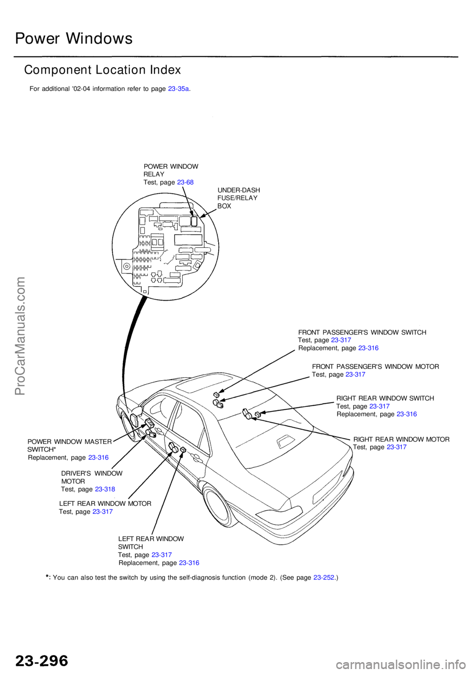
POWER WINDO WRELAYTest, pag e 23-6 8
UNDER-DAS H
FUSE/RELAYBOX
FRON T PASSENGER' S WINDO W SWITC H
Test , pag e 23-31 7
Replacement , pag e 23-31 6
FRON T PASSENGER' S WINDO W MOTO R
Test , pag e 23-31 7
RIGH T REA R WINDO W SWITC H
Test , pag e 23-31 7
Replacement , pag e 23-31 6
RIGH T REA R WINDO W MOTO R
Test , pag e 23-31 7
POWE
R WINDO W MASTE R
SWITCH*Replacement , pag e 23-31 6
DRIVER' S WINDO W
MOTO R
Test , pag e 23-31 8
LEF T REA R WINDO W MOTO R
Test , pag e 23-31 7
LEF T REA R WINDO W
SWITC H
Test , pag e 23-31 7
Replacement , pag e 23-31 6
Yo u ca n als o tes t th e switc h b y usin g th e self-diagnosi s functio n (mod e 2) . (Se e pag e 23-252 .)For additional '02-04 information refer to page 23-35a.
ProCarManuals.com
Page 1692 of 1954
*1: '96-9 7 model s*2: '9 8 - 0 0 model s
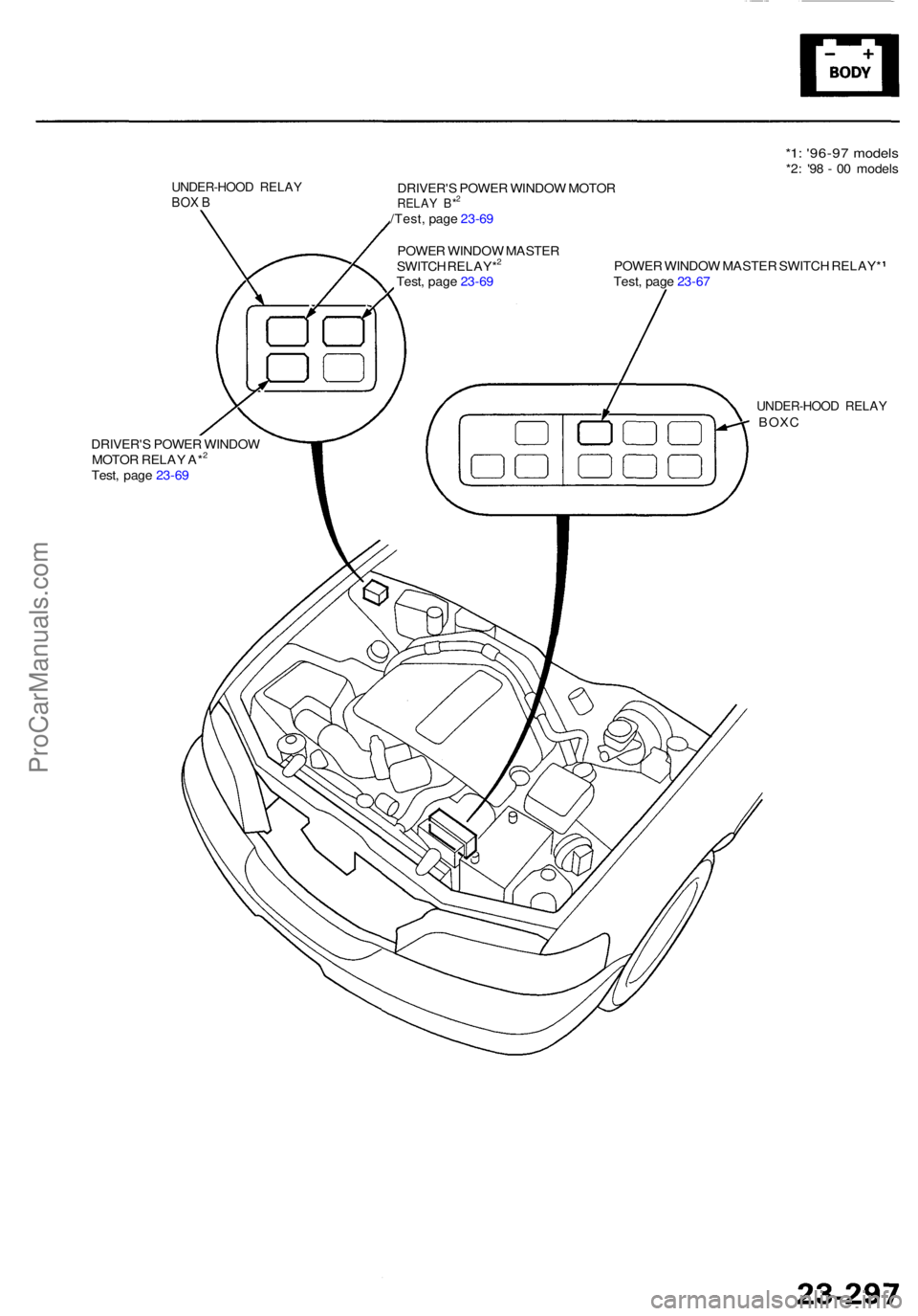
UNDER-HOO D RELA YBOX BDRIVER' S POWE R WINDO W MOTO RRELAY B*2
/Test , pag e 23-6 9
POWE R WINDO W MASTE R
SWITC H RELAY*
2
Test , pag e 23-6 9 POWE
R WINDO W MASTE R SWITC H RELAY *
Test , pag e 23-6 7
DRIVER' S POWE R WINDO W
MOTO R RELA Y A*
2
Test , pag e 23-6 9
UNDER-HOO D RELA Y BOXC
ProCarManuals.com
Page 1702 of 1954
Wiper/Washer
Component Locatio n Inde x
SRS component s ar e locate d in thi s area . Revie w th e SR S componen t locations , precautions , an d procedure s in th e SR S
( sectio n 24 ) befor e performin g repair s o r service .
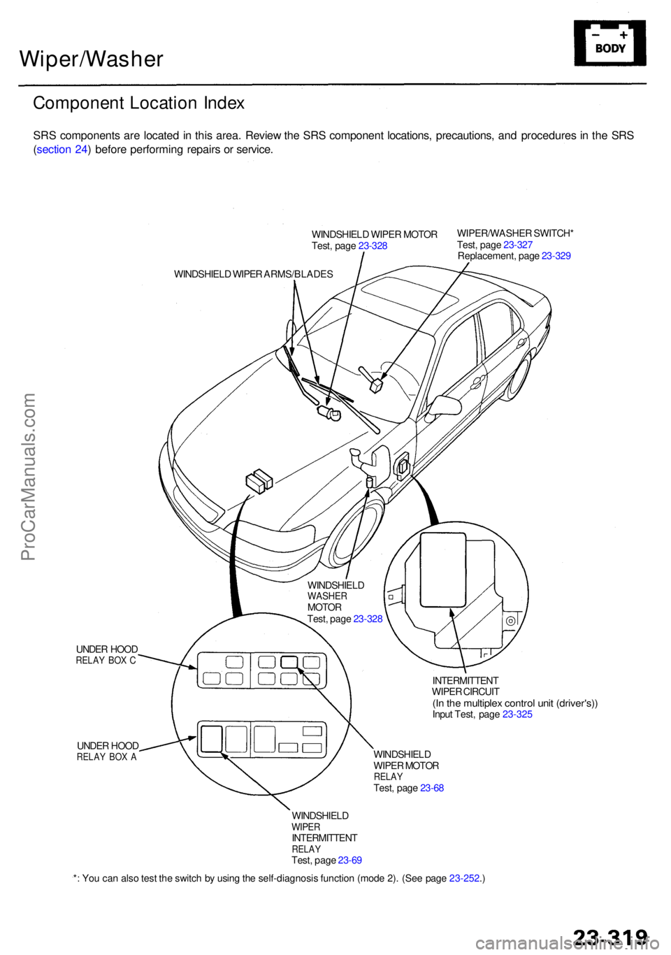
WINDSHIEL D WIPE R MOTO R
Test , pag e 23-32 8 WIPER/WASHE
R SWITCH *
Test , pag e 23-32 7
Replacement , pag e 23-32 9
WINDSHIEL D WIPE R ARMS/BLADE S
UNDE R HOO D
RELA Y BO X C
UNDE R HOO DRELA Y BO X A
INTERMITTEN T
WIPE R CIRCUI T
(In th e multiple x contro l uni t (driver's) )Input Test , pag e 23-32 5
WINDSHIEL D
WIPE R MOTO R
RELAYTest, pag e 23-6 8
* : Yo u ca n als o tes t th e switc h b y usin g th e self-diagnosi s functio n (mod e 2) . (Se e pag e 23-252 .)
WINDSHIEL
D
WASHERMOTORTest, pag e 23-32 8
WINDSHIEL D
WIPERINTERMITTEN TRELAYTest, pag e 23-6 9
ProCarManuals.com
Page 1709 of 1954
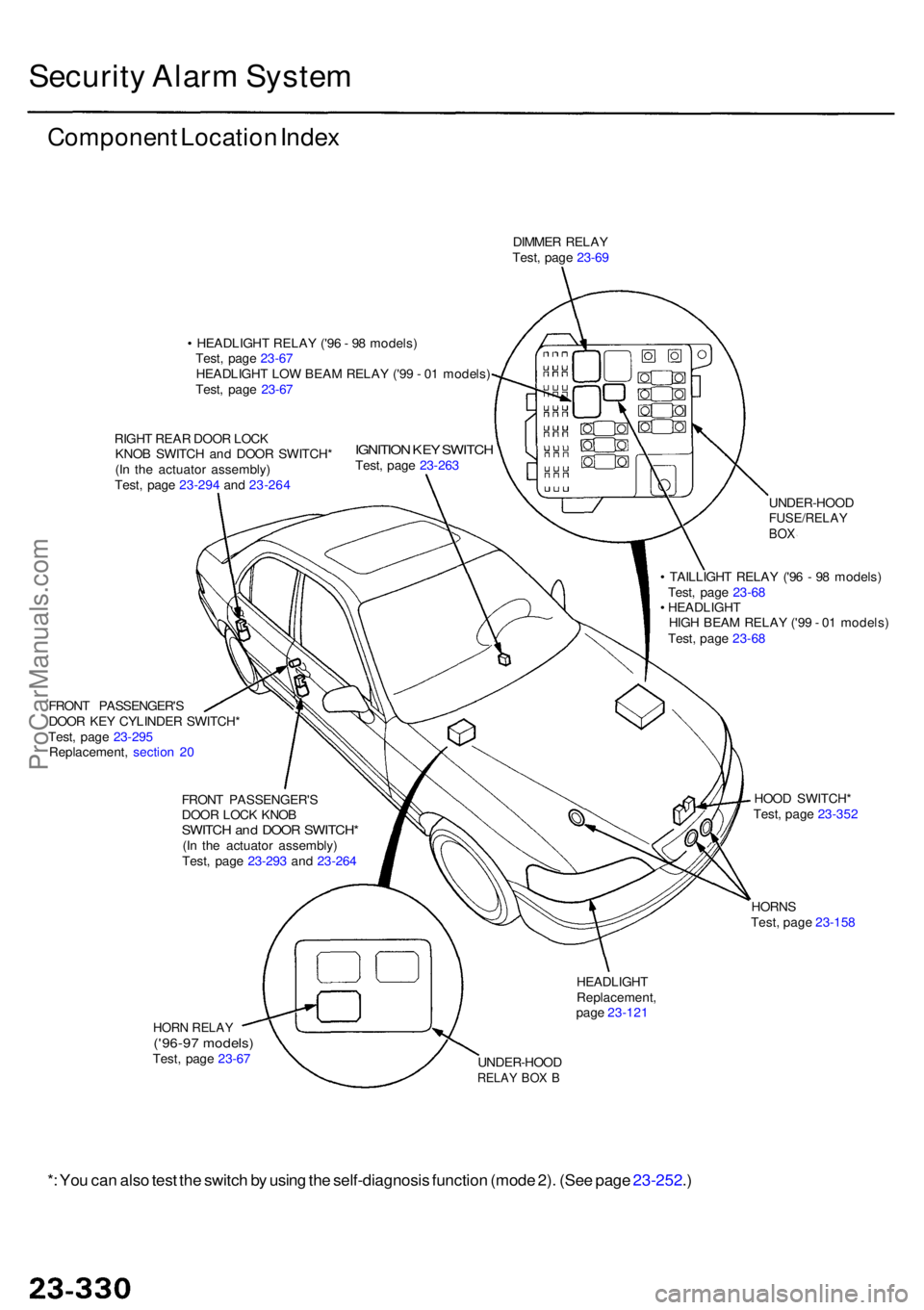
Security Alar m Syste m
Componen t Locatio n Inde x
DIMME R RELA Y
Test , pag e 23-6 9
• HEADLIGH T RELA Y ('9 6 - 9 8 models )
Test , pag e 23-6 7
HEADLIGH T LO W BEA M RELA Y ('9 9 - 0 1 models )
Test , pag e 23-6 7
RIGH T REA R DOO R LOC K
KNO B SWITC H an d DOO R SWITCH *
(I n th e actuato r assembly )
Test , pag e 23-29 4 an d 23-26 4
IGNITIO N KE Y SWITC HTest, pag e 23-26 3
FRON T PASSENGER' S
DOO R KE Y CYLINDE R SWITCH *
Test , pag e 23-29 5
Replacement , sectio n 2 0
FRON T PASSENGER' S
DOO R LOC K KNO B
SWITC H an d DOO R SWITCH *(In th e actuato r assembly )
Test , pag e 23-29 3 an d 23-26 4 UNDER-HOO
D
FUSE/RELAYBOX
• TAILLIGH T RELA Y ('9 6 - 9 8 models )
Test , pag e 23-6 8
• HEADLIGH T
HIG H BEA M RELA Y ('9 9 - 0 1 models )
Test , pag e 23-6 8
HOO D SWITCH *
Test , pag e 23-35 2
HORN S
Test , pag e 23-15 8
HEADLIGH TReplacement ,
pag e 23-12 1
UNDER-HOO D
RELAY BO X B
HOR N RELA Y('96-97 models )Test, pag e 23-6 7
*: Yo u ca n als o tes t th e switc h b y usin g th e self-diagnosi s functio n (mod e 2) . (Se e pag e 23-252 .)
ProCarManuals.com
Page 1722 of 1954
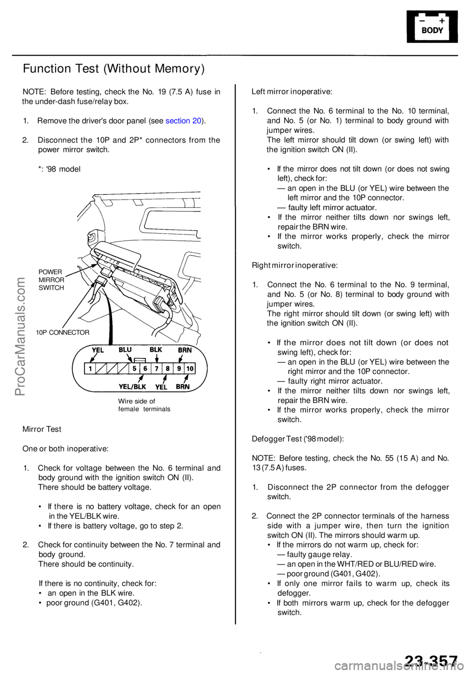
Function Tes t (Withou t Memory )
NOTE: Befor e testing , chec k th e No . 1 9 (7. 5 A ) fus e i n
th e under-das h fuse/rela y box .
1 . Remov e th e driver' s doo r pane l (se e sectio n 20 ).
2 . Disconnec t th e 10 P an d 2P * connector s fro m th e
powe r mirro r switch .
* : '9 8 mode l
POWE RMIRRO RSWITCH
10 P CONNECTO R
Mirror Tes t
On e o r bot h inoperative :
1 . Chec k fo r voltag e betwee n th e No . 6 termina l an d
bod y groun d wit h th e ignitio n switc h O N (II) .
Ther e shoul d b e batter y voltage .
• I f ther e i s n o batter y voltage , chec k fo r a n ope n
i n th e YEL/BL K wire .
• I f ther e is batter y voltage , g o to ste p 2 .
2 . Chec k fo r continuit y betwee n th e No . 7 termina l an d
bod y ground .
Ther e shoul d b e continuity .
I f ther e is n o continuity , chec k for :
• a n ope n in th e BL K wire .
• poo r groun d (G401 , G402) . Lef
t mirro r inoperative :
1 . Connec t th e No . 6 termina l t o th e No . 1 0 terminal ,
an d No . 5 (o r No . 1 ) termina l t o bod y groun d wit h
jumpe r wires .
Th e lef t mirro r shoul d til t dow n (o r swin g left ) wit h
th e ignitio n switc h O N (II) .
• I f th e mirro r doe s no t til t dow n (o r doe s no t swin g
left) , chec k for :
— an ope n in th e BL U (o r YEL ) wir e betwee n th e
lef t mirro r an d th e 10 P connector .
— fault y lef t mirro r actuator .
• I f th e mirro r neithe r tilt s dow n no r swing s left ,
repai r th e BR N wire .
• I f th e mirro r work s properly , chec k th e mirro r
switch .
Righ t mirro r inoperative :
1 . Connec t th e No . 6 termina l t o th e No . 9 terminal ,
an d No . 5 (o r No . 8 ) termina l t o bod y groun d wit h
jumpe r wires .
Th e righ t mirro r shoul d til t dow n (o r swin g left ) wit h
th e ignitio n switc h O N (II) .
• I f th e mirro r doe s no t til t dow n (o r doe s no t
swin g left) , chec k for :
— an ope n in th e BL U (o r YEL ) wir e betwee n th e
righ t mirro r an d th e 10 P connector .
— fault y righ t mirro r actuator .
• I f th e mirro r neithe r tilt s dow n no r swing s left ,
repai r th e BR N wire .
• I f th e mirro r work s properly , chec k th e mirro r
switch .
Defogge r Tes t ('9 8 model) :
NOTE : Befor e testing , chec k th e No . 5 5 (1 5 A ) an d No .
1 3 (7. 5 A ) fuses .
1 . Disconnec t th e 2 P connecto r fro m th e defogge r
switch .
2 . Connec t th e 2 P connecto r terminal s o f th e harnes s
sid e wit h a jumpe r wire , the n tur n th e ignitio n
switc h O N (II) . Th e mirror s shoul d war m up .
• I f th e mirror s d o no t war m up , chec k for :
— fault y gaug e relay .
— an ope n in th e WHT/RE D o r BLU/RE D wire .
— poo r groun d (G401 , G402) .
• I f onl y on e mirro r fail s t o war m up , chec k it s
defogger .
• I f bot h mirror s war m up , chec k fo r th e defogge r
switch .
Wire sid e o ffemal e terminal s
ProCarManuals.com
Page 1758 of 1954
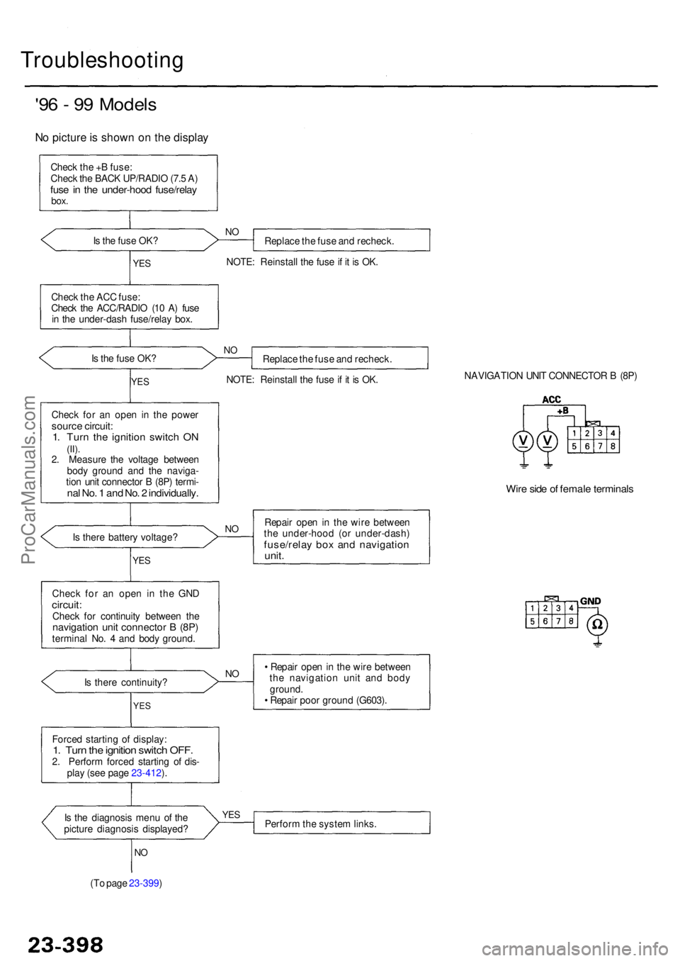
Troubleshooting
'96 - 9 9 Model s
No pictur e is show n o n th e displa y
Check th e + B fuse :
Chec k th e BAC K UP/RADI O (7. 5 A )
fus e in th e under-hoo d fuse/rela ybox.
Is th e fus e OK ?
Replace th e fus e an d recheck .NO
NOTE : Reinstal l th e fus e if i t i s OK .YES
Chec k th e AC C fuse :
Chec k th e ACC/RADI O (1 0 A ) fus e
i n th e under-das h fuse/rela y box .
I s th e fus e OK ?
NOReplac e th e fus e an d recheck .
NOTE : Reinstal l th e fus e if i t i s OK .
YES
Chec k fo r a n ope n i n th e powe rsource circuit :1. Tur n th e ignitio n switc h O N(II).2. Measur e th e voltag e betwee n
bod y groun d an d th e naviga -
tio n uni t connecto r B (8P ) termi -
nal No . 1 an d No . 2 individually .
NAVIGATIO N UNI T CONNECTO R B (8P )
Wire sid e o f femal e terminal s
Repair ope n in th e wir e betwee n
th e under-hoo d (o r under-dash )
fuse/relay bo x an d navigatio nunit.
Is ther e batter y voltage ?NO
YE S
Chec k fo r a n ope n i n th e GN Dcircuit :Check fo r continuit y betwee n th enavigatio n uni t connecto r B (8P )termina l No . 4 an d bod y ground .
I s ther e continuity ?
NO• Repai r ope n in th e wir e betwee n
th e navigatio n uni t an d bod y
ground .
• Repai r poo r groun d (G603) .
YES
Force d startin g o f display :1. Tur n th e ignitio n switc h OFF .2. Perfor m force d startin g o f dis -
pla y (se e pag e 23-412 ).
I s th e diagnosi s men u o f th e
pictur e diagnosi s displayed ?
YESPerfor m th e syste m links .
NO
(T o pag e 23-399 )
ProCarManuals.com
Page 1761 of 1954
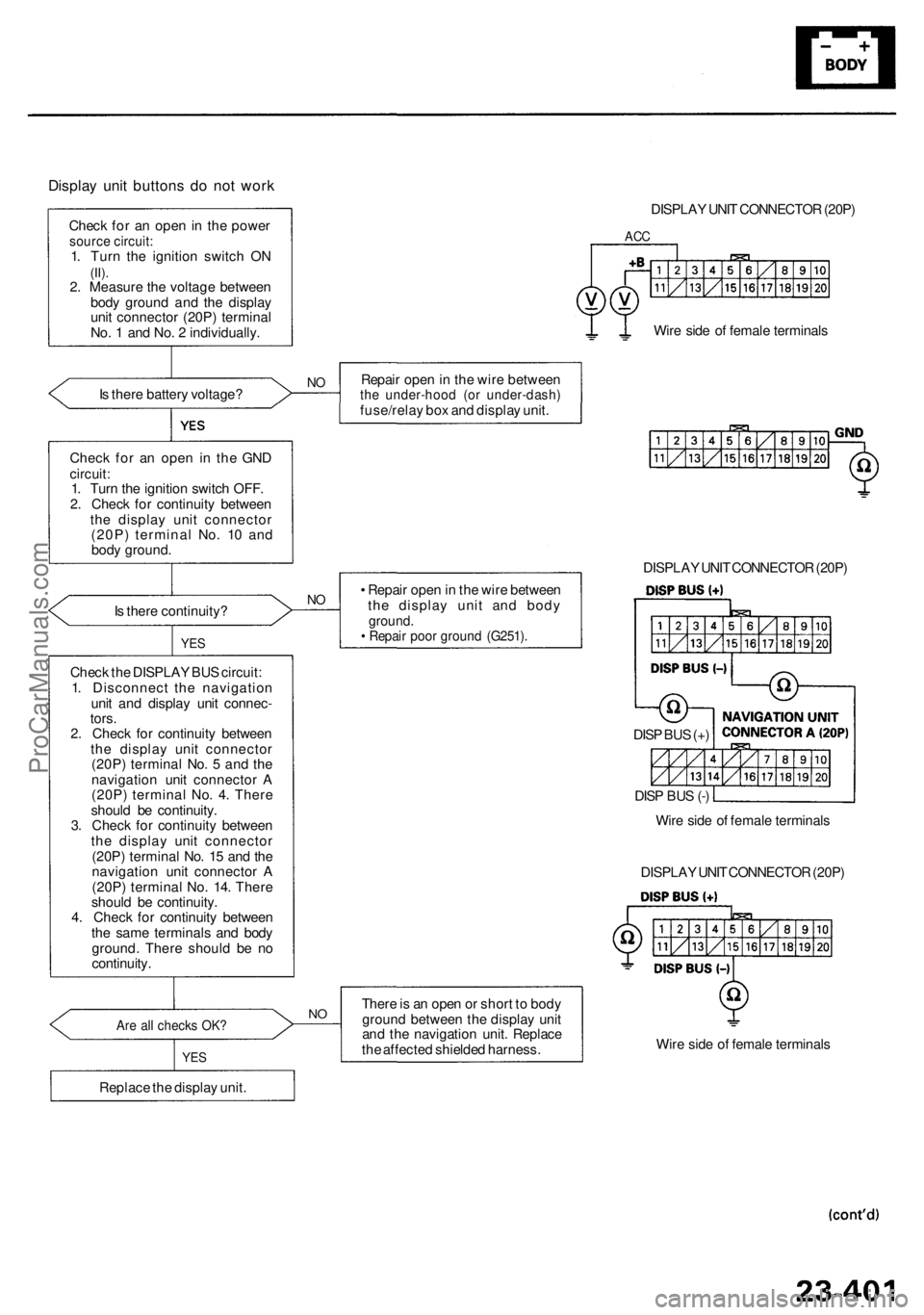
Display uni t button s d o no t wor k
Chec k fo r a n ope n in th e powe rsource circuit :1. Tur n th e ignitio n switc h O N(II).2. Measur e th e voltag e betwee n
bod y groun d an d th e displa y
uni t connecto r (20P ) termina l
No . 1 an d No . 2 individually .
I s ther e batter y voltage ?
NORepai r ope n in th e wir e betwee nthe under-hoo d (o r under-dash )fuse/relay bo x an d displa y unit .
Chec k fo r a n ope n i n th e GN D
circuit :1. Tur n th e ignitio n switc h OFF .
2 . Chec k fo r continuit y betwee n
th e displa y uni t connecto r
(20P ) termina l No . 1 0 an d
bod y ground .
I s ther e continuity ?
NO• Repai r ope n in th e wir e betwee n
th e displa y uni t an d bod y
ground .• Repai r poo r groun d (G251) .
Check th e DISPLA Y BU S circuit :
1 . Disconnec t th e navigatio n
uni t an d displa y uni t connec -
tors .
2 . Chec k fo r continuit y betwee n
th e displa y uni t connecto r
(20P ) termina l No . 5 an d th e
navigatio n uni t connecto r A
(20P ) termina l No . 4 . Ther e
shoul d b e continuity .
3 . Chec k fo r continuit y betwee n
th e displa y uni t connecto r
(20P ) termina l No . 1 5 an d th e
navigatio n uni t connecto r A
(20P ) termina l No . 14 . Ther e
shoul d b e continuity .
4 . Chec k fo r continuit y betwee n
th e sam e terminal s an d bod y
ground . Ther e shoul d b e n o
continuity .
YES
Are al l check s OK ?
YES
Replac e th e displa y unit .
NOTher e is a n ope n o r shor t t o bod y
groun d betwee n th e displa y uni t
an d th e navigatio n unit . Replac e
th e affecte d shielde d harness . Wir
e sid e o f femal e terminal s
DISPLA
Y UNI T CONNECTO R (20P )
DISPLA
Y UNI T CONNECTO R (20P )
ACC
Wir e sid e o f femal e terminal s
DISPLA Y UNI T CONNECTO R (20P )
Wir e sid e o f femal e terminal s
DIS
P BU S (+ )
DIS P BU S (- )
ProCarManuals.com