1996 ACURA RL KA9 relay
[x] Cancel search: relayPage 1158 of 1954
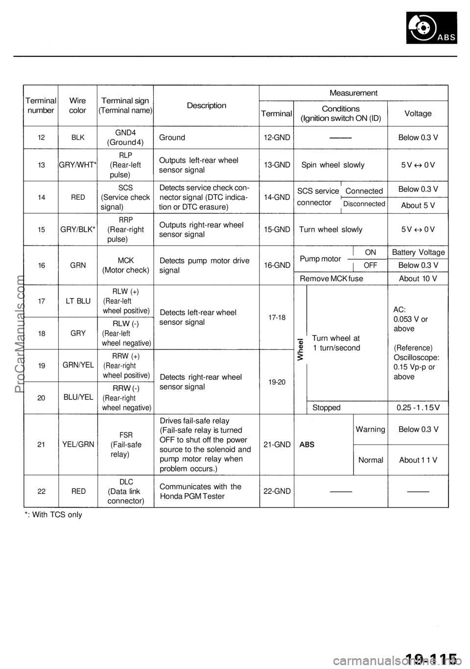
Terminal
number
12
13
1 4
15
16
17
1 8
19
2 0
2 1
2 2
Wir e
colo r
BLK
GRY/WHT *
RED
GRY/BLK *
GRN
LT BL U
GR Y
GRN/YE L
BLU/YEL
YEL/GR N
RED
Termina l sig n
(Termina l name )
GND4
(Groun d 4 )
RL P
(Rear-lef t
pulse)
SCS
(Servic e chec k
signal )
RRP
(Rear-righ t
pulse)
MCK
(Moto r check )
RLW (+ )
(Rear-lef t
wheel positive )
RLW (-)
(Rear-lef t
wheel negative )
RRW (+ )
(Rear-righ t
wheel positive )
RRW (-)
(Rear-righ t
wheel negative )
FSR
(Fail-saf e
relay)
DLC
(Dat a lin k
connector )
Description
Ground
Output s left-rea r whee l
senso r signa l
Detect s servic e chec k con -
necto r signa l (DT C indica -
tio n o r DT C erasure )
Output s right-rea r whee l
senso r signa l
Detect s pum p moto r driv e
signa l
Detect s left-rea r whee l
senso r signa l
Detect s right-rea r whee l
senso r signa l
Drive s fail-saf e rela y
(Fail-saf e rela y is turne d
OF F to shu t of f th e powe r
sourc e to th e solenoi d an d
pum p moto r rela y whe n
proble m occurs. )
Communicate s wit h th e
Hond a PG M Teste r
Measuremen t
Terminal
12-GND
13-GND
14-GN D
15-GND
16-GND
17-18
19-2 0
21-GN D
22-GN D
Condition s
(Ignition switch ON (ID )
Spi n whee l slowl y
SC S servic e Connecte d
connecto r
Disconnecte d
Turn whee l slowl y
ONPum p moto r —————OF F
Remov e MC K fus e
Tur n whee l a t
1 turn/secon d
Stoppe d
Warnin g
Norma l
Voltage
Below 0. 3 V
5 V 0 V
Below 0. 3 V
Abou t 5 V
5V 0 V
Batter y Voltag e
Belo w 0. 3 V
Abou t 1 0 V
AC :
0.05 3 V or
abov e
(Reference )
Oscilloscope :
0.15 Vp- p o r
abov e
0.25 -1.15 V
Below 0. 3 V
Abou t 1 1 V
* : Wit h TC S onl y
ProCarManuals.com
Page 1159 of 1954
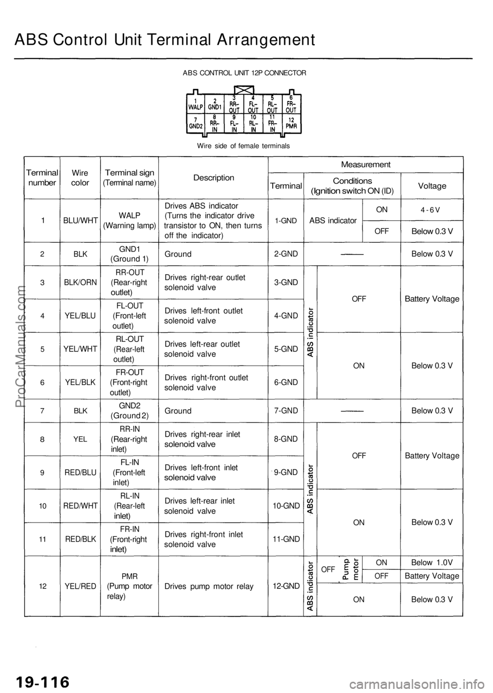
ABS Contro l Uni t Termina l Arrangemen t
ABS CONTRO L UNI T 12 P CONNECTO R
Wir e sid e o f femal e terminal s
Terminal
number
1
2
3
4
5
6
7
8
9
10
1 1
12
Wir e
colo r
BLU/WH T
BLK
BLK/OR N
YEL/BLU
YEL/WH T
YEL/BLK
BLK
YE L
RED/BL U
RED/WH T
RED/BLK
YEL/RE D
Terminal sig n
(Termina l name )
WALP
(Warnin g lamp )
GND1
(Groun d 1 )
RR-OU T
(Rear-righ t
outlet)
FL-OU T
(Front-lef t
outlet )
RL-OU T
(Rear-lef t
outlet)
FR-OU T
(Front-righ t
outlet )
GND 2
(Groun d 2 )
RR-I N
(Rear-righ t
inlet )
FL-I N
(Front-lef t
inlet )
RL-I N
(Rear-lef t
inlet)
FR-I N
(Front-righ t
inlet)
PMR
(Pum p moto r
relay)
Descriptio n
Drives AB S indicato r
(Turn s th e indicato r driv e
transisto r t o ON , the n turn s
of f th e indicator )
Groun d
Drive s right-rea r outle t
solenoi d valv e
Drive s left-fron t outle t
solenoi d valv e
Drive s left-rea r outle t
solenoi d valv e
Drive s right-fron t outle t
solenoi d valv e
Groun d
Drive s right-rea r inle t
solenoi d valv e
Drive s left-fron t inle t
solenoi d valv e
Drive s left-rea r inle t
solenoi d valv e
Drive s right-fron t inle t
solenoi d valv e
Drive s pum p moto r rela y
Measuremen t
Terminal
1-GND
2-GN D
3-GND
4-GN D
5-GND
6-GN D
7-GN D
8-GND
9-GND
10-GN D
11-GND
12-GND
Condition s
(Ignition switch ON (ID )
AB S indicato r
ON
OF F
OFF
ON
OF F
ON
OF FON
OF F
ON
Voltag e
4-6V
Below 0. 3 V
Belo w 0. 3 V
Batter y Voltag e
Below 0. 3 V
Belo w 0. 3 V
Batter y Voltag e
Belo w 0. 3 V
Belo w 1.0 V
Batter y Voltag e
Belo w 0. 3 V
ProCarManuals.com
Page 1160 of 1954
Troubleshooting Precautions
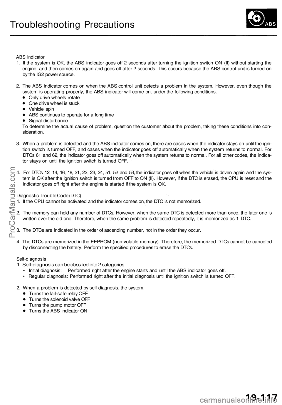
ABS Indicator
1. If the system is OK, the ABS indicator goes off 2 seconds after turning the ignition switch ON (II) without starting the
engine, and then comes on again and goes off after 2 seconds. This occurs because the ABS control unit is turned on
by the IG2 power source.
2. The ABS indicator comes on when the ABS control unit detects a problem in the system. However, even though the
system is operating properly, the ABS indicator will come on, under the following conditions.
Only drive wheels rotate
One drive wheel is stuck
Vehicle spin
ABS continues to operate for a long time
Signal disturbance
To determine the actual cause of problem, question the customer about the problem, taking these conditions into con-
sideration.
3. When a problem is detected and the ABS indicator comes on, there are cases when the indicator stays on until the igni-
tion switch is turned OFF, and cases when the indicator goes off automatically when the system returns to normal. For
DTCs 61 and 62, the indicator goes off automatically when the system returns to normal. For all other codes, the indica-
tor stays on until the ignition switch is turned OFF.
4. For DTCs 12, 14, 16, 18, 21, 22, 23, 24, 51, 52 and 53, the indicator goes off when the vehicle is driven again and the sys-
tem is OK after the ignition switch is turned from OFF to ON (II). However, if the DTC is erased, the CPU is reset and the
indicator goes off right after the engine is started if the system is OK.
Diagnostic Trouble Code (DTC)
1. If the CPU cannot be activated and the indicator comes on, the DTC is not memorized.
2. The memory can hold any number of DTCs. However, when the same DTC is detected more than once, the later one is
written over the old one. Therefore, when the same problem is detected repeatedly, it is memorized as 1 DTC.
3. The DTCs are indicated in the order of ascending number, not in the order they occur.
4. The DTCs are memorized in the EEPROM (non-volatile memory). Therefore, the memorized DTCs cannot be canceled
by disconnecting the battery. Perform the specified procedures to erase the DTCs.
Self-diagnosis
1. Self-diagnosis can be classified into 2 categories.
• Initial diagnosis: Performed right after the engine starts and until the ABS indicator goes off.
• Regular diagnosis: Performed right after the initial diagnosis until the ignition switch is turned OFF.
2. When a problem is detected by self-diagnosis, the system.
Turns the fail-safe relay OFF
Turns the solenoid valve OFF
Turns the pump motor OFF
Turns the ABS indicator ONProCarManuals.com
Page 1177 of 1954
Troubleshooting
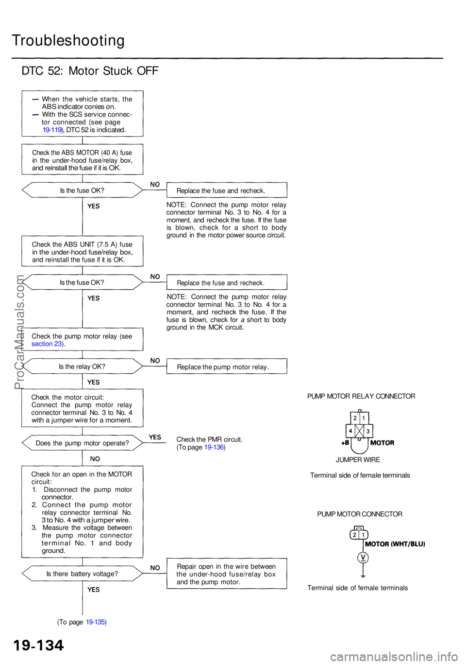
DTC 52 : Moto r Stuc k OF F
Whe n th e vehicl e starts , th eAB S indicato r conie s on .Wit h th e SC S servic e connec -
to r connecte d (se e pag e
19-119 ), DT C 52 is indicated .
Check th e AB S MOTO R (4 0 A ) fus ein th e under-hoo d fuse/rela y box ,and reinstal l th e fus e if i t i s OK .
Is th e fus e OK ?
Chec k th e AB S UNI T (7. 5 A ) fus e
in th e under-hoo d fuse/rela y box ,and reinstal l th e fus e if i t i s OK .
I s th e fus e OK ?
Chec k th e pum p moto r rela y (se e
sectio n 23 ).
I s th e rela y OK ?
Chec k th e moto r circuit :
Connec t th e pum p moto r rela y
connecto r termina l No . 3 to No . 4
wit h a jumpe r wir e fo r a moment .
Does th e pum p moto r operate ?
Chec k fo r a n ope n in th e MOTO R
circuit :
1 . Disconnec t th e pum p moto r
connector .2. Connec t th e pum p moto rrelay connecto r termina l No .3 to No . 4 wit h a jumpe r wire .3. Measur e th e voltag e betwee n
th e pum p moto r connecto r
terminal No . 1 an d bod yground .
Is ther e batter y voltage ?
(T o pag e 19-135 ) Replac
e th e fus e an d recheck .
NOTE : Connec t th e pum p moto r rela y
connecto r termina l No . 3 to No . 4 fo r a
moment , an d rechec k th e fuse . I f th e fus e
i s blown , chec k fo r a shor t t o bod y
groun d i n th e moto r powe r sourc e circuit .
Replac e th e fus e an d recheck .
NOTE: Connec t th e pum p moto r rela y
connecto r termina l No . 3 to No . 4 fo r a
moment , an d rechec k th e fuse . I f th efus e i s blown , chec k fo r a shor t t o bod y
groun d i n th e MC K circuit .
Replac e th e pum p moto r relay .
PUMP MOTO R RELA Y CONNECTO R
Chec k th e PM R circuit .
(T o pag e 19-136 )
Repai r ope n in th e wir e betwee n
th e under-hoo d fuse/rela y bo x
an d th e pum p motor .
Terminal sid e o f femal e terminal s
PUM
P MOTO R CONNECTO R
JUMPE
R WIR E
Termina l sid e o f femal e terminal s
ProCarManuals.com
Page 1180 of 1954
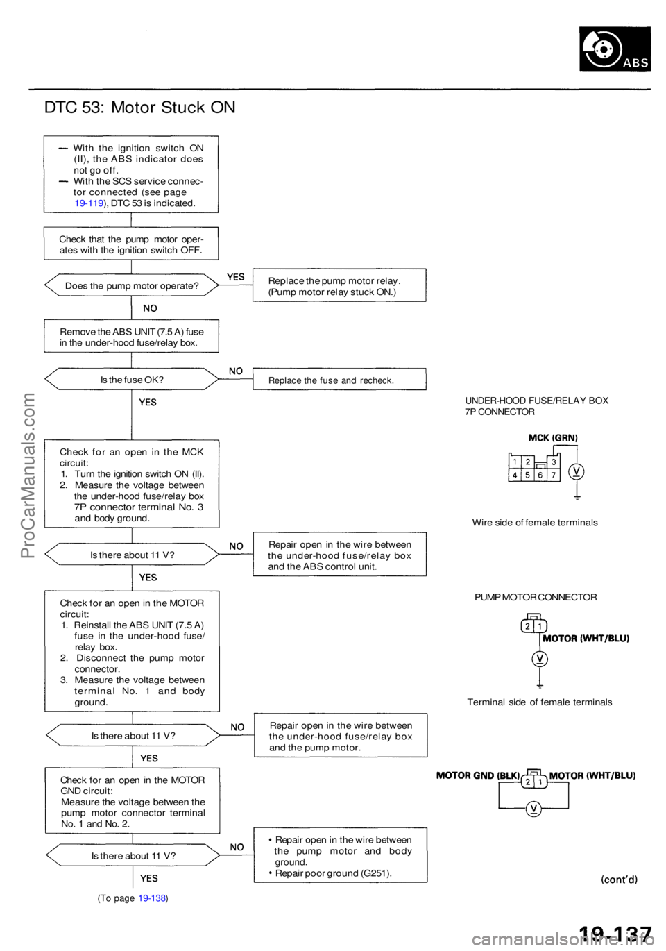
DTC 53 : Moto r Stuc k O N
Wit h th e ignitio n switc h O N
(II) , th e AB S indicato r doe s
not g o off .Wit h th e SC S servic e connec -
to r connecte d (se e pag e
19-119 ), DT C 53 is indicated .
Chec k tha t th e pum p moto r oper -
ate s wit h th e ignitio n switc h OFF .
Doe s th e pum p moto r operate ?
Remov e th e AB S UNI T (7. 5 A ) fus e
i n th e under-hoo d fuse/rela y box .
I s th e fus e OK ?
Chec k fo r a n ope n i n th e MC K
circuit :1. Tur n th e ignitio n switc h O N (II) .
2 . Measur e th e voltag e betwee n
th e under-hoo d fuse/rela y bo x
7P connecto r termina l No . 3an d bod y ground .
I s ther e abou t 1 1 V ?
Chec k fo r a n ope n in th e MOTO R
circuit:1. Reinstal l th e AB S UNI T (7. 5 A )
fus e i n th e under-hoo d fuse /
rela y box .
2 . Disconnec t th e pum p moto r
connector .3. Measur e th e voltag e betwee n
termina l No . 1 an d bod y
ground .
I s ther e abou t 1 1 V ?
Chec k fo r a n ope n in th e MOTO R
GN D circuit :
Measur e th e voltag e betwee n th e
pum p moto r connecto r termina l
No. 1 an d No . 2 .
Is ther e abou t 1 1 V ?
(To pag e 19-138 )
Replac e th e pum p moto r relay .
(Pum p moto r rela y stuc k ON. )
Replac e th e fus e an d recheck .
UNDER-HOO D FUSE/RELA Y BO X7P CONNECTO R
Wire sid e o f femal e terminal s
Repai r ope n in th e wir e betwee n
th e under-hoo d fuse/rela y bo x
an d th e AB S contro l unit .
PUMP MOTO R CONNECTO R
Termina l sid e o f femal e terminal s
Repai r ope n in th e wir e betwee n
th e under-hoo d fuse/rela y bo x
an d th e pum p motor .
Repai r ope n in th e wir e betwee n
th e pum p moto r an d bod y
ground .Repair poo r groun d (G251) .
ProCarManuals.com
Page 1181 of 1954
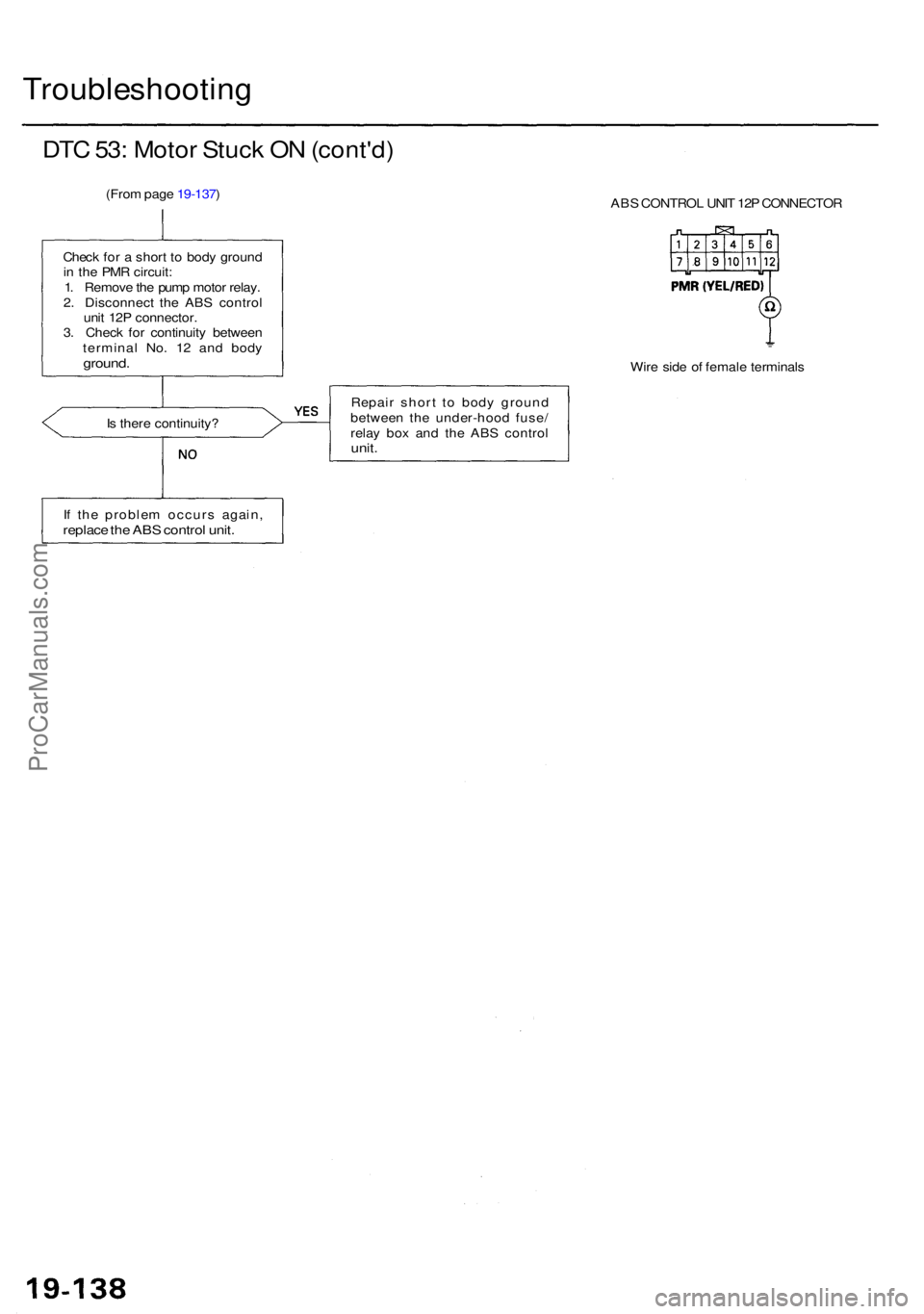
Troubleshooting
DTC 53 : Moto r Stuc k O N (cont'd )
(From pag e 19-137 )
ABS CONTRO L UNI T 12 P CONNECTO R
Chec k fo r a shor t t o bod y groun d
i n th e PM R circuit :
1 . Remov e th e pum p moto r relay .
2 . Disconnec t th e AB S contro l
uni t 12 P connector .
3 . Chec k fo r continuit y betwee n
termina l No . 1 2 an d bod y
ground .Wire sid e o f femal e terminal s
I s ther e continuity ? Repai
r shor t t o bod y groun d
betwee n th e under-hoo d fuse /
rela y bo x an d th e AB S contro l
unit.
If th e proble m occur s again ,replace th e AB S contro l unit .
ProCarManuals.com
Page 1182 of 1954
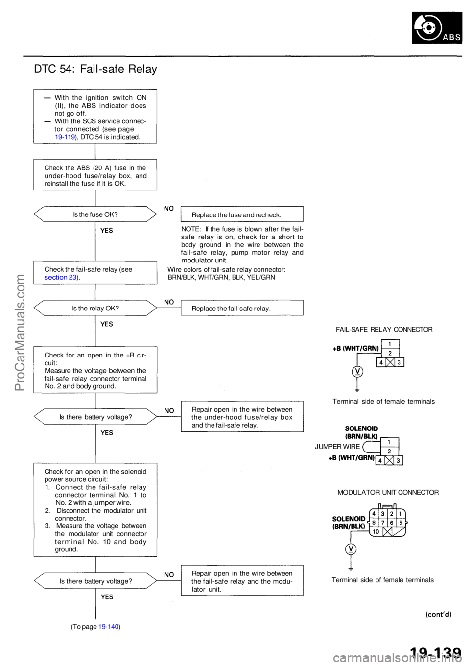
DTC 54 : Fail-saf e Rela y
With th e ignitio n switc h O N
(II) , th e AB S indicato r doe s
not g o off .With th e SC S servic e connec -
to r connecte d (se e pag e
19-119 ), DT C 5 4 is indicated .
Check th e AB S (2 0 A ) fus e i n th eunder-hoo d fuse/rela y box , an d
reinstal l th e fus e if i t i s OK .
I s th e fus e OK ?
Replace th e fus e an d recheck .
NOTE : I f th e fus e i s blow n afte r th e fail -
saf e rela y i s on , chec k fo r a shor t t o
bod y groun d i n th e wir e betwee n th e
fail-saf e relay , pum p moto r rela y an d
modulato r unit .
Wire color s o f fail-saf e rela y connector :BRN/BLK, WHT/GRN , BLK , YEL/GR N
Is th e rela y OK ?
Replace th e fail-saf e relay .
Chec k fo r a n ope n in th e + B cir -
cuit :
Measur e th e voltag e betwee n th efail-saf e rela y connecto r termina lNo. 2 an d bod y ground .
FAIL-SAF E RELA Y CONNECTO R
Is ther e batter y voltage ? Repai
r ope n in th e wir e betwee n
th e under-hoo d fuse/rela y bo x
an d th e fail-saf e relay . Termina
l sid e o f femal e terminal s
Chec k fo r a n ope n in th e solenoi d
powe r sourc e circuit :
1 . Connec t th e fail-saf e rela y
connecto r termina l No . 1 to
No . 2 wit h a jumpe r wire .2. Disconnec t th e modulato r uni t
connector .
3 . Measur e th e voltag e betwee n
th e modulato r uni t connecto r
terminal No . 1 0 an d bod yground . MODULATO
R UNI T CONNECTO R
I s ther e batter y voltage ?
(T o pag e 19-140 ) Repai
r ope n in th e wir e betwee n
th e fail-saf e rela y an d th e modu -
lato r unit . Termina
l sid e o f femal e terminal s
JUMPE
R WIR E
Chec
k th e fail-saf e rela y (se e
sectio n 23).
ProCarManuals.com
Page 1183 of 1954
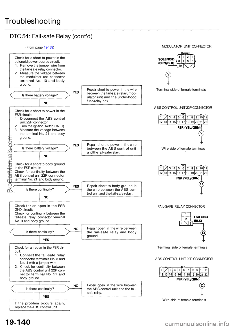
Troubleshooting
DTC 54 : Fail-saf e Rela y (cont'd )
(From pag e 19-139 )
Chec k fo r a shor t t o powe r i n th e
solenoi d powe r sourc e circuit :
1 . Remov e th e jumpe r wir e fro m
th e fail-safe relay connector .
2 . Measur e th e voltag e betwee n
th e modulato r uni t connecto r
terminal No . 1 0 an d bod yground .
I s ther e batter y voltage ?
Chec k fo r a shor t t o powe r i n th e
FS R circuit :1. Disconnec t th e AB S contro lunit 22 P connector .
2 . Tur n th e ignitio n switc h O N (II) .
3 . Measur e th e voltag e betwee n
th e termina l No . 2 1 an d bod y
ground .
I s ther e batter y voltage ?
Chec k fo r a shor t t o bod y groun d
i n th e FS R circuit :
Chec k fo r continuit y betwee n th e
AB S contro l uni t 22 P connecto rterminal No . 2 1 an d bod y ground .
I s ther e continuity ?
Chec k fo r a n ope n i n the FSR
GN D circuit :
Chec k fo r continuit y betwee n th e
fail-saf e rela y connecto r termina l
No . 3 an d bod y ground .
I s ther e continuity ?
Check fo r a n ope n in th e FS R cir -cuit :1. Connec t th e fail-saf e rela yconnecto r terminal s No . 3 an dNo. 4 wit h a jumpe r wire .
2 . Chec k fo r continuit y betwee n
th e AB S contro l uni t 22 P con -
necto r termina l No . 2 1 an d
bod y ground .
I s ther e continuity ?
I f th e proble m occur s again ,
replac e th e AB S contro l unit . Repai
r shor t t o powe r i n th e wir e
betwee n th e fail-saf e relay , mod -
ulator uni t an d th e under-hoo dfuse/relay box .
Termina l sid e o f femal e terminal s
ABS CONTRO L UNI T 22 P CONNECTO R
Repai r shor t t o powe r i n th e wir e
betwee n th e AB S contro l uni tand th e fail-saf e relay .Wire sid e o f femal e terminal s
Repair shor t t o bod y groun d in
th e wir e betwee n th e AB S con -
tro l uni t an d th e fail-saf e relay .
FAIL-SAF E RELA Y CONNECTO R
Repair ope n in th e wir e betwee n
th e fail-saf e rela y an d bod y
ground .
Termina l sid e o f femal e terminal s
AB S CONTRO L UNI T 22 P CONNECTO R
Repai r ope n i n th e wir e betwee n
th e AB S contro l uni t an d th e fail -
saf e relay .
Wire sid e o f femal e terminal s
MODULATO
R UNI T CONNECTO R
ProCarManuals.com