Page 1030 of 2543
Check TRAC solenoid relay.
Remove solenoid relay from R/B No.5.
Check continuity between each terminal of TRAC
solenoid relay shown below.
Repair or replace harness or connector.
Check and replace TRAC ECU.
Replace TRAC solenoid relay.
Apply battery positive voltage between termi-
nals 4 and 6
.
Check continuity between each terminal of
TRAC solenoid relay shown below.
Terminals 4 and 6
Terminals 2 and 3
Terminals 1 and 3
Continuity
Open
Continuity
(Reference value 80 �)
Check for open and short in harness and connector between terminal WT
of TRAC ECU and battery or TRAC solenoid relay (See page IN±30).
Connect the � test lead to terminal 5 and the �
lead to terminal 3. Check continuity between the
terminals.
Continuity
If there is no continuity, connect the
� test lead to
terminal 5 and the
� lead to terminal 3. Recheck
continuity between terminals.
Terminals 2 and 3
Terminals 1 and 3Continuity
Open
± BRAKE SYSTEMTRACTION CONTROL SYSTEM (TRAC)BR±161
Page 1031 of 2543
TRAC Indicator Light Circuit
CIRCUIT DESCRIPTION
The TRAC indicator blinks during TRAC operation.
This indicator is also used for warnings when the trouble occurs and for displaying diagnostic trouble
codes.
Repair or replace harness or connector.
Check and replace TRAC ECU.
Repair circuit indicated by the code output.
Check diagnostic trouble code (See page BR±126).
INSPECTION PROCEDURES
Troubleshoot in accordance with flow chart instructions for each trouble symptom.
TRAC Indicator light does not light up
Go to Combination Meter Troubleshooting on page BE±43.
TRAC Indicator light remains ON
Check for short in harness and connector between TRAC ECU and TRAC
indicator light (See page IN±30).
Indicator light remains ONOutput
NG Code
BR±162± BRAKE SYSTEMTRACTION CONTROL SYSTEM (TRAC)
Page 1032 of 2543
Tc Terminal Circuit
CIRCUIT DESCRIPTION
By connecting terminals Tc and E1 of DLC1 or DLC2, the ECU displays the diagnostic trouble code
by blinking the TRAC indicator light.
± BRAKE SYSTEMTRACTION CONTROL SYSTEM (TRAC)BR±163
Page 1033 of 2543
(See page IN±30).
Check voltage between terminals Tc and E1 of DLC2 or DLC1.
Turn ignition switch ON
Measure voltage between terminals Tc and E1 of DLC2
or DLC1.
Voltage: 10 Ð 14 V
Proceed to next circuit inspection shown on
problem symptoms chart (See page BR±133).
Repair or replace harness or connector.
Check and replace TRAC ECU.
Check for open and short in harness and connector of symptoms con-
nected to Tc terminal (See page IN±30).
INSPECTION PROCEDURE
BR±164± BRAKE SYSTEMTRACTION CONTROL SYSTEM (TRAC)
Page 1034 of 2543
Check for Fluid Leakage
± BRAKE SYSTEMTRACTION CONTROL SYSTEM (TRAC)BR±165
Page 1176 of 2543

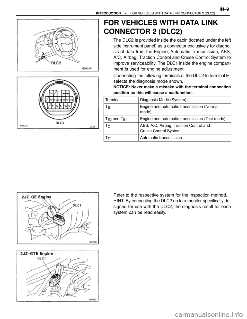
FOR VEHICLES WITH DATA LINK
CONNECTOR 2 (DLC2)
The DLC2 is provided inside the cabin (located under the left
side instrument panel) as a connector exclusively for diagno-
sis of data from the Engine, Automatic Transmission, ABS,
A/C, Airbag, Traction Control and Cruise Control System to
improve serviceability. The DLC1 inside the engine compart-
ment is used for engine adjustment.
Connecting the following terminals of the DLC2 to terminal E
1
selects the diagnosis mode shown.
NOTICE: Never make a mistake with the terminal connection
position as this will cause a malfunction.
������� �������Terminal���������������� ����������������Diagnosis Mode (System)
������� �
������ �������TE1���������������� �
��������������� ����������������Engine and automatic transmission (Normal
mode)
������� �������TE2 and TE1���������������� ����������������Engine and automatic transmission (Test mode)������� �
������ �������TC���������������� �
��������������� ����������������ABS, A/C, Airbag, Traction Control and
Cruise Control System
������� �������TT���������������� ����������������Automatic transmission
Refer to the respective system for the inspection method.
HINT: By connecting the DLC2 up to a monitor specifically de-
signed for use with the DLC2, the diagnosis result for each
system can be read easily.
± INTRODUCTIONFOR VEHICLES WITH DATA LINK CONNECTOR 2 (DLC2)IN±9
Page 1183 of 2543
FOR VEHICLES EQUIPPED WITH
TRACTION CONTROL (TRAC) SYSTEM
When using a rear wheel two±wheel drum tester such as a
speedometer tester or chassis dynamometer, etc., or jacking
up the rear wheels and driving the wheels, always push in the
TRAC cut (ºTRAC OFFº) switch and turn the TRAC system
OFF.
CONFIRM TRAC SYSTEM IS OFF
1. Press the TRAC cut (ºTRAC OFFº) switch.
2. Check that the TRAC OFF indicator light comes on when the
TRAC system is turned off by the TRAC cut switch.
HINT: The TRAC indicator light should always operate right
after the engine is restarted.
3. Begin measurements.
4. Press the TRAC cut switch again to change the TRAC to
operative and check that the TRAC OFF indicator light goes
off.
HINT: The TRAC indicator light blinks when the TRAC system
is operative. IN±16
± INTRODUCTIONPRECAUTION
Page 1186 of 2543

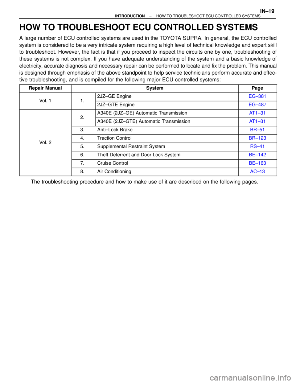
HOW TO TROUBLESHOOT ECU CONTROLLED SYSTEMS
A large number of ECU controlled systems are used in the TOYOTA SUPRA. In general, the ECU controlled
system is considered to be a very intricate system requiring a high level of technical knowledge and expert skill
to troubleshoot. However, the fact is that if you proceed to inspect the circuits one by one, troubleshooting of
these systems is not complex. If you have adequate understanding of the system and a basic knowledge of
electricity, accurate diagnosis and necessary repair can be performed to locate and fix the problem. This manual
is designed through emphasis of the above standpoint to help service technicians perform accurate and effec-
tive troubleshooting, and is compiled for the following major ECU controlled systems:
�������� ��������Repair Manual������������������������ ������������������������System������ ������Page
�������� ��������
Vol 1
���� ����
1
��������������������� ���������������������2JZ±GE Engine������ ������EG±381
�������� ��������Vol. 1���� ���� 1.��������������������� ���������������������2JZ±GTE Engine������ ������EG±487
�������� ������������ ����
2
��������������������� ���������������������A340E (2JZ±GE) Automatic Transmission������ ������AT1±31�������� ������������ ���� 2.��������������������� ���������������������A340E (2JZ±GTE) Automatic Transmission������ ������AT1±31�������� �
������� ��������
���� �
��� ���� 3.
��������������������� �
�������������������� ���������������������Anti±Lock Brake
������ �
����� ������BR±51
�������� ��������Vol 2���� ���� 4.��������������������� ���������������������Traction Control������ ������BR±123
�������� ��������Vol. 2���� ���� 5.��������������������� ���������������������Supplemental Restraint System������ ������RS±41
�������� ������������ ���� 6.��������������������� ���������������������Theft Deterrent and Door Lock System������ ������BE±142
�������� ������������ ���� 7.��������������������� ���������������������Cruise Control������ ������BE±163
�������� ������������ ���� 8.��������������������� ���������������������Air Conditioning������ ������AC±13
The troubleshooting procedure and how to make use of it are described on the following pages.
± INTRODUCTIONHOW TO TROUBLESHOOT ECU CONTROLLED SYSTEMSIN±19