Page 1006 of 2543

DTC 25 26 TRAC Sub±Throttle Valve
����� �����DTC No.���������������� ����������������Diagnostic Trouble Code Detecting Condition����������������� �����������������Trouble area����� �
���� �
���� �
���� �
���� �
���� �
���� �
���� �����
25
���������������� �
��������������� �
��������������� �
��������������� �
��������������� �
��������������� �
��������������� �
��������������� ����������������
The difference between the sub±throttle
sensor signal voltage and the voltage
required by the step count is 1 V or more.
����������������� �
���������������� �
���������������� �
���������������� �
���������������� �
���������������� �
���������������� �
���������������� �����������������
� Sub±throttle actuator.
� Throttle body (sub±throttle valve is stuck
or operation is faulty).
� Sub±throttle position sensor.
� Open or short in sub±throttle position sensor cir±
cuit.
� ECM
� TRAC ECU
����� �
���� �
���� �
���� �
���� �
���� �
���� �����
26
���������������� �
��������������� �
��������������� �
��������������� �
��������������� �
��������������� �
��������������� ����������������
Even when sub±throttle valve is driven to the
fully open position, input voltage at terminal
VTA2 of ECM does not come within range of
the specifications 3±4.5 V.
����������������� �
���������������� �
���������������� �
���������������� �
���������������� �
���������������� �
���������������� �����������������
� Sub±throttle actuator.
� Throttle body (sub±throttle valve is stuck
or operation is faulty).
� Sub±throttle position sensor.
� Open or short in sub±throttle position sensor cir
cuit.
� ECM
� TRAC ECU
Remove air duct.
Open and close the sub±throttle valve manually and check
the condition during operation.
The valve should operate smoothly without catching.
HINT: If sub throttle actuator, sub±throttle valve, sub±throttle posi±
tion sensor and harness are free from any defect, ECM may
be defective.
If ECM is free from any defect, TRAC ECU may be defec±
tive.
± BRAKE SYSTEMTRACTION CONTROL SYSTEM (TRAC)BR±137
Page 1007 of 2543

DTC 31 32 33 34 Speed Sensor Circuit
HINT: DTC No.31 is for the right front speed sensor.
DTC No.32 is for the left front speed sensor.
DTC No.33 is for the right rear speed sensor.
DTC No.34 is for the left rear speed sensor.
CIRCUIT DESCRIPTION
The speed sensor detects the wheel speed and sends the ap-
propriate signals to the ECU. These signals are used to control
both the ABS and TRAC control systems. The front and rear ro-
tors each have 48 serrations. When the rotors rotate, the magnet-
ic field emitted by the permanent magnet in the speed sensor
generates an AC voltage. Since the frequency of this AC voltage
changes in direct proportion to the speed of the rotor, the frequen-
cy is used by the ECU to detect the speed of each wheel.
Diagnostic Trouble Code Detecting ConditionTrouble areaDTC No.
Detection of any of conditions (1) through
(3):
At vehicle speed of 10 km/h (6 mph) or
more, pulses are not input for 5 sec.
Momentary interruption of the vehicle
speed sensor signal occurs at least 7
times in the time between switching the
ignition switch ON and switching it OFF.
Abnormal fluctuation of speed sensor
signals with the vehicle speed 20 km/h
(12 mph) or more.
Right front, left front, right rear and left
rear speed sensor.
Open or short in each speed sensor circuit.
ECU
BR±138± BRAKE SYSTEMTRACTION CONTROL SYSTEM (TRAC)
Page 1008 of 2543
± BRAKE SYSTEMTRACTION CONTROL SYSTEM (TRAC)BR±139
Page 1009 of 2543
.
(See page IN±30).
(See page BR±62).
Remove front fender splash shield.
Disconnect speed sensor connector.
Measure resistance between terminals 1 and 2 of
speed sensor connector.
R")
(See page IN±30).
(See page IN±30).
(See page BR±62).
Remove front fender splash shield.
Disconnect speed sensor connector.
Measure resistance between terminals 1 and 2 of
speed sensor connector.
Resistance: 0.7 ± 1.7 k�
Resistance: 1 M� or higher
Remove rear seat cushion, seat back and quarter
trim panel.
Disconnect speed sensor connector.
Measure resistance between terminals 1 and 2 of
speed sensor connector.
Resistance: 0.7 ± 1.7 k�
Measure resistance between terminals 1 and 2 of
speed sensor connector and body ground.
Resistance: 1 M� or higher
Repair or replace harness or connector.
Check speed sensor.
Check for open and short in harness and connector between terminals FRO,
FLO, RRO, RLO of ABS & TRAC ECU and TRAC ECU (See page IN±30).
Front
Rear
Replace speed sensor.
NOTICE: Check the speed sensor signal last (See page BR±62).
Check for open and short in harness and connector between each speed
sensor and ECU (See page IN±30).
Repair and replace harness or connector.
INSPECTION PROCEDURE
HINT: If the same code is output from the ABS warning light, troubleshoot the ABS first. BR±140
± BRAKE SYSTEMTRACTION CONTROL SYSTEM (TRAC)
Page 1010 of 2543
(See page SA±15).
(See page SA±45).
Remove front speed sensor rotor
(See page SA±15).
Check sensor rotor serrations.
No scratches or missing teeth.
Check the front speed sensor installation.
The installation bolt is tightened properly.
Remove the drive shaft (See page SA±45).
Check the sensor rotor serrations.
No scratches or missing teeth.
Front
Rear
Check sensor rotor and sensor installation.
Check the rear speed sensor installation.
The installation bolt is tightened properly and
there is no clearance between the sensor and rear
axle carrier.
Replace speed sensor or rotor.
Check and replace ABS (& TRAC) ECU.
NOTICE: Check the speed sensor signal last (See page BR±62).
± BRAKE SYSTEMTRACTION CONTROL SYSTEM (TRAC)BR±141
Page 1011 of 2543
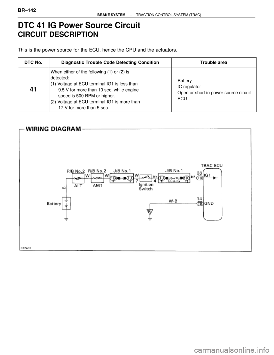
DTC 41 IG Power Source Circuit
CIRCUIT DESCRIPTION
This is the power source for the ECU, hence the CPU and the actuators.
������ ������DTC No.������������������ ������������������Diagnostic Trouble Code Detecting Condition�������������� ��������������Trouble area
������ �
����� �
����� �
����� �
����� �
����� �
����� ������
41
������������������ �
����������������� �
����������������� �
����������������� �
����������������� �
����������������� �
����������������� ������������������
When either of the following (1) or (2) is
detected:
(1) Voltage at ECU terminal IG1 is less than
9.5 V for more than 10 sec. while engine
speed is 500 RPM or higher.
(2) Voltage at ECU terminal IG1 is more than
17 V for more than 5 sec.
�������������� �
������������� �
������������� �
������������� �
������������� �
������������� �
������������� ��������������
� Battery
� IC regulator
� Open or short in power source circuit
� ECU
BR±142± BRAKE SYSTEMTRACTION CONTROL SYSTEM (TRAC)
Page 1012 of 2543
INSPECTION PROCEDURE
Check battery positive voltage.
Voltage: 10 ± 14 V
Check and repair the charging system.
Remove TRAC ECU with connectors still
connected.
Turn ignition switch ON.
Measure voltage between terminals IG1 and
GND of TRAC ECU connector.
Voltage: 10 ± 14 V
Check voltage between terminals IG1 and GND of TRAC ECU connector.
Check and replace TRAC ECU.
Measure resistance between terminal GND of
TRAC ECU connector and body ground.
Resistance: 1� or less
Check continuity between terminal GND of TRAC ECU connector and
body ground.
Repair or replace harness or connector.
± BRAKE SYSTEMTRACTION CONTROL SYSTEM (TRAC)BR±143
Page 1013 of 2543
(See page IN±30).
Remove ECU±IG fuse from J/B No. 1.
Check continuity of ECU±IG fuse.
Continuity
Check ECU±IG fuse.
Check for short in all the harness and components
connected to ECU±IG fuse.
Check for open in harness and connector between
TRAC ECU and battery (See page IN±30).
BR±144± BRAKE SYSTEMTRACTION CONTROL SYSTEM (TRAC)
BR±139")
.
(See page SA±45).
Remove front speed sensor rotor
(See page SA±15).
Check sensor rotor serrations.
No scratches or missing teeth.
Check the front speed sensor installation.
The in")

.
Remove ECU±IG fuse from J/B No. 1.
Check continuity of ECU±IG fuse.
Continuity
Check ECU±IG fuse.
Check for short in all the harness and components
connected to ECU±IG fuse.
Che")