Page 998 of 2543
PARTS LOCATION
± BRAKE SYSTEMTRACTION CONTROL SYSTEM (TRAC)BR±129
Page 999 of 2543
ECU TERMINALS STANDARD VALUE
ABS & TRAC ECU:
ConditionSTD Voltage (V)Symbols
(Terminals No.)
Always
IG switch ON
IG switch ON, ABS warning light OFF
IG switch ON
IG switch ON, TRAC and TRAC OFF indicator light OFF
IG switch ON
IG switch ON, ABS warning light OFF
IG switch ON, ABS warning light OFF
IG switch ON, ABS warning light OFF
IG switch ON, ABS warning light OFF
IG switch ON, ABS warning light OFF
IG switch ON, TRAC and TRAC OFF indicator light OFF
IG switch ON, TRAC and TRAC OFF indicator light OFF
IG switch ON, ABS warning light ON
IG switch ON, ABS warning light OFF
IG switch ON, PKB switch ON
Fluid in M/C reservoir above MIN level.
IG switch ON, PKB switch OFF
Fluid in M/C reservoir above MIN level.
IG switch ON
Fluid in M/C reservoir above MIN level.
Stop light switch OFF
Stop light switch ON
IG switch ON, ABS warning light OFF
BR±130± BRAKE SYSTEMTRACTION CONTROL SYSTEM (TRAC)
Page 1000 of 2543
ConditionsSTD Voltage (V)Symbols
(Terminal No.)
IG switch ON
IG switch ON
IG switch ON
Slowly turn right front wheel.
IG switch ON
Slowly turn left front wheel.
IG switch ON
Slowly turn right rear wheel.
IG switch ON
Slowly turn left rear wheel.
IG switch ON
Slowly turn right front wheel.
IG switch ON
Slowly turn left front wheel.
IG switch ON
Slowly turn right rear wheel.
IG switch ON
Slowly turn left rear wheel.
IG switch ON, Vehicle parked on a level surface
IG switch ON, Vehicle parked on a level surface
IG switch ON
AC generation
AC generation
AC generation
Pulse generation
Pulse generation
Pulse generation
Pulse generation
± BRAKE SYSTEMTRACTION CONTROL SYSTEM (TRAC)BR±131
Page 1001 of 2543

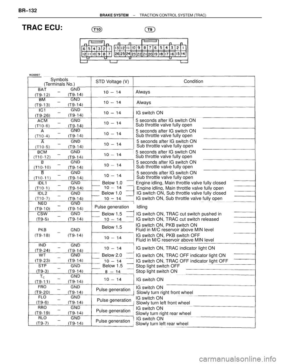
TRAC ECU:
ConditionSTD Voltage (V)Symbols
(Terminals No.)
Always
Always
IG switch ON
5 seconds after IG switch ON
Sub throttle valve fully open
5 seconds after IG switch ON
Sub throttle valve fully open
5 seconds after IG switch ON
Sub throttle valve fully open
5 seconds after IG switch ON
Sub throttle valve fully open
5 seconds after IG switch ON
Sub throttle valve fully open
5 seconds after IG switch ON
Sub throttle valve fully open
Engine idling, Main throttle valve fully closed
Engine idling, Main throttle valve fully open
IG switch ON, Sub throttle valve fully closed
IG switch ON, Sub throttle valve fully open
Idling
IG switch ON, TRAC cut switch pushed in
IG switch ON, TRAC cut switch released
IG switch ON, PKB switch ON
Fluid in M/C reservoir above MIN level
IG switch ON, PKB switch OFF
Fluid in M/C reservoir above MIN level
IG switch ON, TRAC indicator light ON
IG switch ON, TRAC OFF indicator light ON
IG switch ON, TRAC OFF indicator light OFF
Stop light switch OFF
Stop light switch ON
IG switch ON
IG switch ON
Slowly turn right front wheel
IG switch ON
Slowly turn left front wheel
IG switch ON
Slowly turn right rear wheel
IG switch ON
Slowly turn left rear wheel
Below 1.0
Below 1.0
Pulse generation
Below 1.5
Below 1.5
Below 2.0
Below 1.5
Pulse generation
Pulse generation
Pulse generation
Pulse generation
BR±132± BRAKE SYSTEMTRACTION CONTROL SYSTEM (TRAC)
Page 1002 of 2543

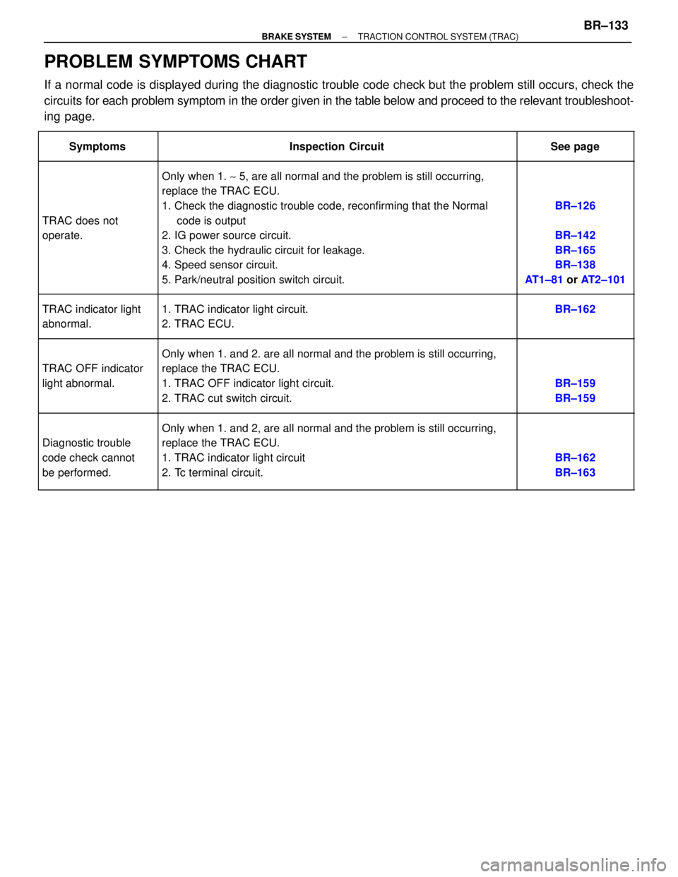
PROBLEM SYMPTOMS CHART
If a normal code is displayed during the diagnostic trouble code check but the problem still occurs, check the
circuits for each problem symptom in the order given in the table below and proceed to the relevant troubleshoot-
ing page.
�������� �
������� ��������Symptoms
���������������������� �
��������������������� ����������������������Inspection Circuit
�������� �
������� ��������See page
�������� �
������� �
������� �
������� �
������� �
������� �
������� �
������� ��������
TRAC does not
operate.
���������������������� �
��������������������� �
��������������������� �
��������������������� �
��������������������� �
��������������������� �
��������������������� �
��������������������� ����������������������
Only when 1. ~ 5, are all normal and the problem is still occurring,
replace the TRAC ECU.
1. Check the diagnostic trouble code, reconfirming that the Normal
code is output
2. IG power source circuit.
3. Check the hydraulic circuit for leakage.
4. Speed sensor circuit.
5. Park/neutral position switch circuit.�������� �
������� �
������� �
������� �
������� �
������� �
������� �
������� ��������
BR±126
BR±142
BR±165
BR±138
AT1±81 or AT2±101
�������� �
������� ��������TRAC indicator light
abnormal.���������������������� �
��������������������� ����������������������1. TRAC indicator light circuit.
2. TRAC ECU.�������� �
������� ��������BR±162
�������� �
������� �
������� �
������� �
������� ��������
TRAC OFF indicator
light abnormal.
���������������������� �
��������������������� �
��������������������� �
��������������������� �
��������������������� ����������������������
Only when 1. and 2. are all normal and the problem is still occurring,
replace the TRAC ECU.
1. TRAC OFF indicator light circuit.
2. TRAC cut switch circuit.
�������� �
������� �
������� �
������� �
������� ��������
BR±159
BR±159
�������� �
������� �
������� �
������� ��������
Diagnostic trouble
code check cannot
be performed.
���������������������� �
��������������������� �
��������������������� �
��������������������� ����������������������
Only when 1. and 2, are all normal and the problem is still occurring,
replace the TRAC ECU.
1. TRAC indicator light circuit
2. Tc terminal circuit.�������� �
������� �
������� �
������� ��������
BR±162
BR±163
± BRAKE SYSTEMTRACTION CONTROL SYSTEM (TRAC)BR±133
Page 1003 of 2543
CIRCUIT INSPECTION
DTC 24 TRAC Sub±Throttle Actuator Circuit
CIRCUIT DESCRIPTION
The sub±throttle actuator operates in accordance with signals from the ECU, controlling the opening
and closing of the sub±throttle valve.
Open or short in sub±throttle actuator circuit.
Diagnostic Trouble Code Detecting ConditionDTC No.Trouble area
TRAC fuse
Open or short in BM circuit.
Sub±throttle actuator.
Open or short in sub±throttle actuator
circuit.
ECU
BR±134± BRAKE SYSTEMTRACTION CONTROL SYSTEM (TRAC)
Page 1004 of 2543
Remove TRAC fuse from R/B No.2.
Check continuity of TRAC fuse.
Continuity
Check TRAC fuse.
Check for short in all harness and components
connected to TRAC fuse.
INSPECTION PROCEDURE
Check voltage between terminals BM and GND of TRAC ECU.
Remove TRAC ECU with connectors still connected.
Measure voltage between terminals BM and GND of
TRAC ECU.
Voltage: 10 ± 14 V
Check and repair harness or connector.
± BRAKE SYSTEMTRACTION CONTROL SYSTEM (TRAC)BR±135
Page 1005 of 2543
(See page IN±30).
Disconnect sub±throttle actuator connector.
Check continuity between each terminal of sub±throttle
actuator connector shown below.
Terminals 1 and 2
Terminals 2 and 3
Terminals 4 and 5
Terminals 5 and 6
Continuity
(Reference value 0.9 �)
Check sub±throttle actuator.
Check for open and short in harness and connector between TRAC
ECU and sub±throttle actuator (See page IN±30).
Replace sub±throttle actuator.
Repair or replace harness or connector.
The illustration shows checking for continuity
between 4 ± 5, and 5 ± 6.
Check and replace TRAC ECU.
BR±136± BRAKE SYSTEMTRACTION CONTROL SYSTEM (TRAC)