Page 1163 of 2543
CAMSHAFT POSITION SENSOR
COMPONENTS FOR REMOVAL AND
INSTALLATION
CAMSHAFT POSITION SENSOR
REMOVAL
Installation is in the reverse order of removal.
1. DISCONNECT IAC VALVE CONNECTOR
2. DISCONNECT AIR HOSE FROM IAC VALVE
3. REMOVE ENGINE HANGER
Remove the 2 bolts, ground strap and engine hanger.
Torque: 39 NVm (400 kgfVcm, 29 ftVlbf)
4. DISCONNECT CAMSHAFT POSITION SENSOR
CONNECTORS
5. REMOVE CAMSHAFT POSITION SENSORS
Remove the 4 bolts, 2 camshaft position sensors and 2 gas-
kets.
Torque: 6.4 NVm (65 kgfVcm, 56 in.Vlbf)
IG±28± IGNITION SYSTEM2JZ±GTE
Page 1166 of 2543
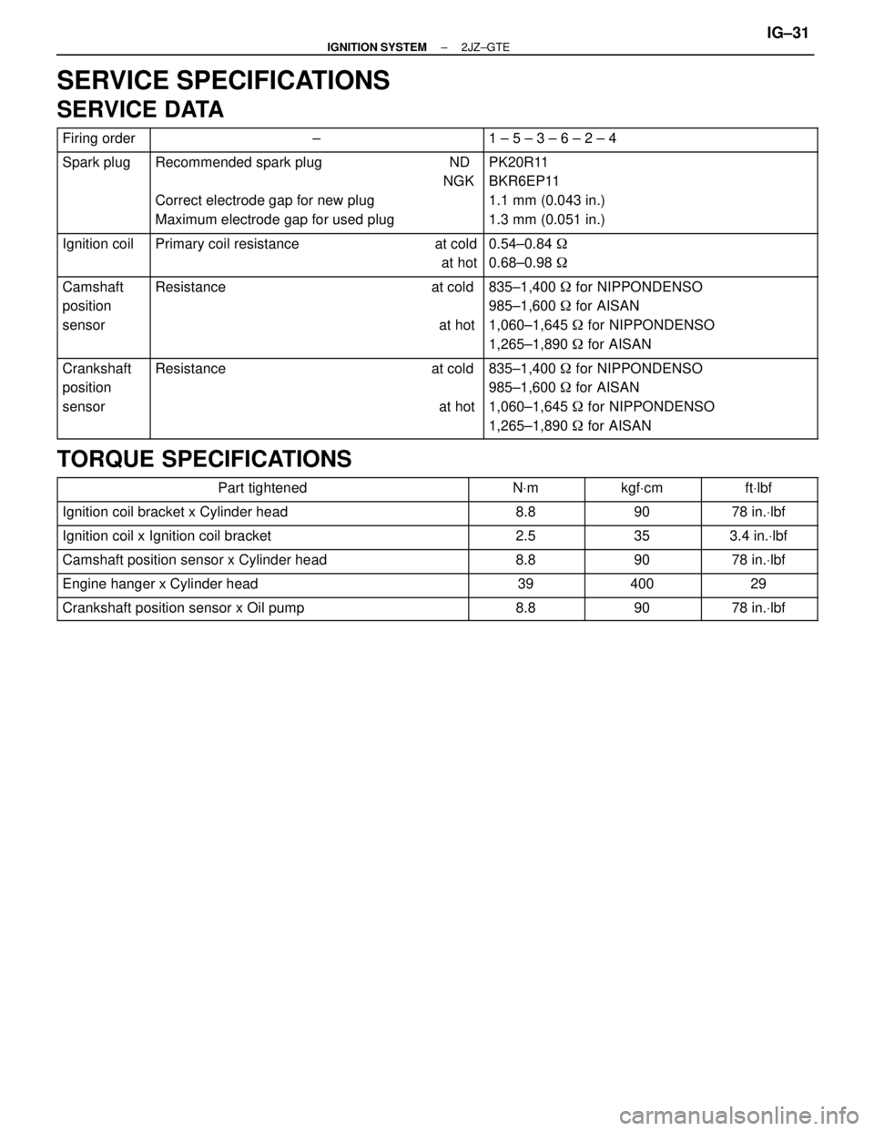
SERVICE SPECIFICATIONS
SERVICE DATA
����� �����Firing order����������������� �����������������±���������������� ����������������1 ± 5 ± 3 ± 6 ± 2 ± 4����� �
���� �
���� �
���� �����
Spark plug����������������� �
���������������� �
���������������� �
���������������� �����������������
Recommended spark plug ND
NGK
Correct electrode gap for new plug
Maximum electrode gap for used plug���������������� �
��������������� �
��������������� �
��������������� ����������������
PK20R11
BKR6EP11
1.1 mm (0.043 in.)
1.3 mm (0.051 in.)
����� �
���� �����
Ignition coil����������������� �
���������������� �����������������
Primary coil resistance at cold
at hot���������������� �
��������������� ����������������
0.54±0.84 �
0.68±0.98 �
����� �
���� �
���� �
���� �����
Camshaft
position
sensor����������������� �
���������������� �
���������������� �
���������������� �����������������
Resistance at cold
at hot���������������� �
��������������� �
��������������� �
��������������� ����������������
835±1,400 � for NIPPONDENSO
985±1,600 � for AISAN
1,060±1,645 � for NIPPONDENSO
1,265±1,890 � for AISAN
����� �
���� �
���� �
���� �����
Crankshaft
position
sensor����������������� �
���������������� �
���������������� �
���������������� �����������������
Resistance at cold
at hot���������������� �
��������������� �
��������������� �
��������������� ����������������
835±1,400 � for NIPPONDENSO
985±1,600 � for AISAN
1,060±1,645 � for NIPPONDENSO
1,265±1,890 � for AISAN
TORQUE SPECIFICATIONS
�������������������� ��������������������Part tightened������ ������NVm������ ������kgfVcm������� �������ftVlbf�������������������� ��������������������Ignition coil bracket x Cylinder head������ ������8.8������ ������90������� �������78 in.Vlbf�������������������� �
������������������� ��������������������Ignition coil x Ignition coil bracket������ �
����� ������2.5������ �
����� ������35������� �
������ �������3.4 in.Vlbf
�������������������� ��������������������Camshaft position sensor x Cylinder head������ ������8.8������ ������90������� �������78 in.Vlbf
�������������������� ��������������������Engine hanger x Cylinder head������ ������39������ ������400������� �������29
�������������������� ��������������������Crankshaft position sensor x Oil pump������ ������8.8������ ������90������� �������78 in.Vlbf
± IGNITION SYSTEM2JZ±GTEIG±31
Page 1170 of 2543
CAUTIONS, NOTICES, HINTS:
wCAUTIONS are presented in bold type, and indicate there is a possibility of injury to you or other
people.
wNOTICES are also presented in bold type, and indicate the possibility of damage to the components
being repaired.
wHINTS are separated from the text but do not appear in bold. They provide additional information to
help you perform the repair efficiently.
SI UNIT
The UNITS given in this manual are primarily expressed according to the SI UNIT (International System
of Unit), and alternately expressed in the metric system and in the English System.
Example:
Torque: 30 NVm (310 kgfVcm, 22 ftVlbf)
IDENTIFICATION INFORMATION
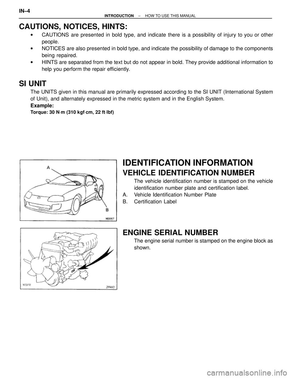
VEHICLE IDENTIFICATION NUMBER
The vehicle identification number is stamped on the vehicle
identification number plate and certification label.
A. Vehicle Identification Number Plate
B. Certification Label
ENGINE SERIAL NUMBER
The engine serial number is stamped on the engine block as
shown. IN±4
± INTRODUCTIONHOW TO USE THIS MANUAL
Page 1171 of 2543
CAUTIONS, NOTICES, HINTS:
wCAUTIONS are presented in bold type, and indicate there is a possibility of injury to you or other
people.
wNOTICES are also presented in bold type, and indicate the possibility of damage to the components
being repaired.
wHINTS are separated from the text but do not appear in bold. They provide additional information to
help you perform the repair efficiently.
SI UNIT
The UNITS given in this manual are primarily expressed according to the SI UNIT (International System
of Unit), and alternately expressed in the metric system and in the English System.
Example:
Torque: 30 NVm (310 kgfVcm, 22 ftVlbf)
IDENTIFICATION INFORMATION
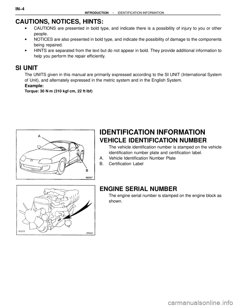
VEHICLE IDENTIFICATION NUMBER
The vehicle identification number is stamped on the vehicle
identification number plate and certification label.
A. Vehicle Identification Number Plate
B. Certification Label
ENGINE SERIAL NUMBER
The engine serial number is stamped on the engine block as
shown. IN±4
± INTRODUCTIONIDENTIFICATION INFORMATION
Page 1174 of 2543
11. Care must be taken when jacking up and supporting the
vehicle. Be sure to lift and support the vehicle at the proper
locations (See page IN±36).
(a) If the vehicle is to be jacked up only at the front or rear
end, be sure to block the wheels at the opposite end in
order to ensure safety.
(b) After the vehicle is jacked up, be sure to support it on
stands. It is extremely dangerous to do any work on a
vehicle raised on a jack alone, even for a small job that
can be finished quickly.
12. Observe the following precautions to avoid damage to the
following parts:
(a) Do not open the cover or case of the ECU, ECM, PCM
or TCM unless absolutely necessary. (If the IC terminals
are touched, the IC may be destroyed by static
electricity.)
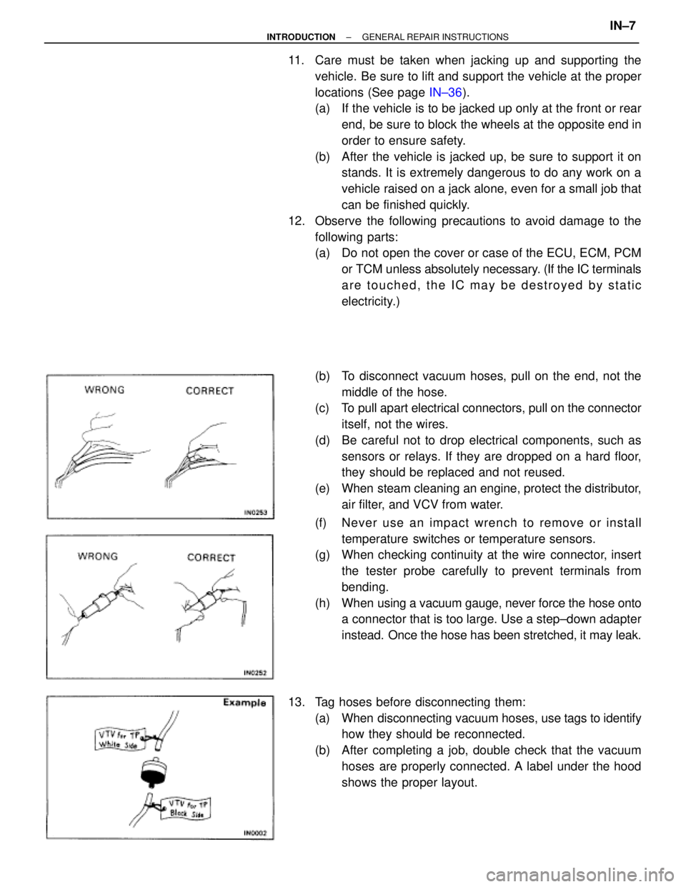
(b) To disconnect vacuum hoses, pull on the end, not the
middle of the hose.
(c) To pull apart electrical connectors, pull on the connector
itself, not the wires.
(d) Be careful not to drop electrical components, such as
sensors or relays. If they are dropped on a hard floor,
they should be replaced and not reused.
(e) When steam cleaning an engine, protect the distributor,
air filter, and VCV from water.
(f) Ne ve r use an imp a ct wre n ch to re mo ve or in sta ll
temperature switches or temperature sensors.
(g) When checking continuity at the wire connector, insert
the tester probe carefully to prevent terminals from
bending.
(h) When using a vacuum gauge, never force the hose onto
a connector that is too large. Use a step±down adapter
instead. Once the hose has been stretched, it may leak.
13. Tag hoses before disconnecting them:
(a) When disconnecting vacuum hoses, use tags to identify
how they should be reconnected.
(b) After completing a job, double check that the vacuum
hoses are properly connected. A label under the hood
shows the proper layout.
± INTRODUCTIONGENERAL REPAIR INSTRUCTIONSIN±7
Page 1175 of 2543
14. Unless otherwise stated, all resistance is measured at an
ambient temperature of 20°C ( 6 8°F). Because the
resistance may be outside specifications if measured at high
temperatures immediately after the vehicle has been
running, measurements should be made when the engine
has cooled down. IN±8
± INTRODUCTIONGENERAL REPAIR INSTRUCTIONS
Page 1176 of 2543
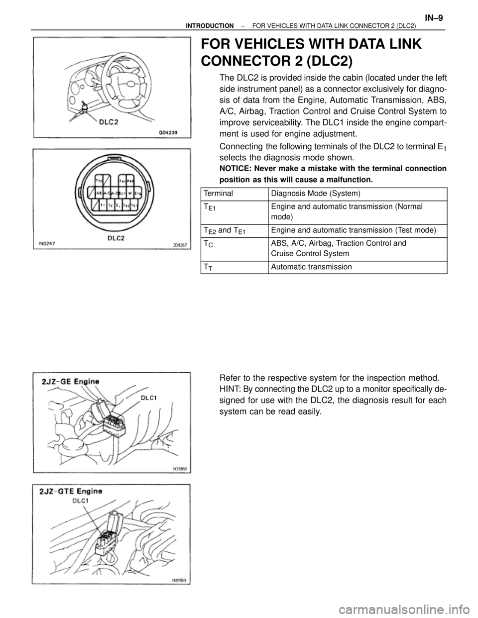
FOR VEHICLES WITH DATA LINK
CONNECTOR 2 (DLC2)
The DLC2 is provided inside the cabin (located under the left
side instrument panel) as a connector exclusively for diagno-
sis of data from the Engine, Automatic Transmission, ABS,
A/C, Airbag, Traction Control and Cruise Control System to
improve serviceability. The DLC1 inside the engine compart-
ment is used for engine adjustment.
Connecting the following terminals of the DLC2 to terminal E
1
selects the diagnosis mode shown.
NOTICE: Never make a mistake with the terminal connection
position as this will cause a malfunction.
������� �������Terminal���������������� ����������������Diagnosis Mode (System)
������� �
������ �������TE1���������������� �
��������������� ����������������Engine and automatic transmission (Normal
mode)
������� �������TE2 and TE1���������������� ����������������Engine and automatic transmission (Test mode)������� �
������ �������TC���������������� �
��������������� ����������������ABS, A/C, Airbag, Traction Control and
Cruise Control System
������� �������TT���������������� ����������������Automatic transmission
Refer to the respective system for the inspection method.
HINT: By connecting the DLC2 up to a monitor specifically de-
signed for use with the DLC2, the diagnosis result for each
system can be read easily.
± INTRODUCTIONFOR VEHICLES WITH DATA LINK CONNECTOR 2 (DLC2)IN±9
Page 1182 of 2543

Wire Harness and Connector
The SRS wire harness is integrated with the cowl wire har-
ness assembly and floor wire harness assembly. The wires
for the SRS wire harness are encased in a yellow corrugated
tube. All the connectors for the system are also a standard
yellow color. If the SRS wire harness becomes disconnected
or the connector becomes broken due to an accident, etc.,
repair or replace it as shown on page RS±36.
FOR VEHICLES EQUIPPED WITH A CATALYTIC CONVERTER
CAUTION: If large amounts of unburned gasoline flow into the converter, it may overheat and create a fire
hazard. To prevent this, observe the following precautions and explain them to your customer.
1. Use only unleaded gasoline.
2. Avoid prolonged idling.
Avoid running the engine at idle speed for more than 20 minutes.
3. Avoid spark jump test.
(a) Perform spark jump test only when absolutely necessary. Perform this test as rapidly as possible.
(b) While testing, never race the engine.
4. Avoid prolonged engine compression measurement.
Engine compression tests must be done as rapidly as possible.
5. Do not run engine when fuel tank is nearly empty.
This may cause the engine to misfire and create an extra load on the converter.
6. Avoid coasting with ignition turned off and prolonged braking.
7. Do not dispose of used catalyst along with parts contaminated with gasoline or oil.
± INTRODUCTIONPRECAUTIONIN±15