Page 1227 of 2543

6. INSTALL OIL STRAINER
Install a new gasket and the oil strainer with the bolt and 2
nuts.
Torque: 8.8 NVm (90 kgfVcm, 78 in.Vlbf)
7. INSTALL NO.2 OIL PAN
(a) Remove any old packing (FIPG) material and be careful not
to drop any oil on the contact surfaces of the No.1 and No.2
oil pans.
wUsing a razor blade and gasket scraper, remove all the
old packing (FIPG) material from the gasket surfaces
and sealing groove.
wThoroughly clean all components to remove all the
debris.
wUsing a non±residue solvent, clean both sealing
surfaces.
NOTICE: Do not use a solvent which will affect the painted sur-
faces.
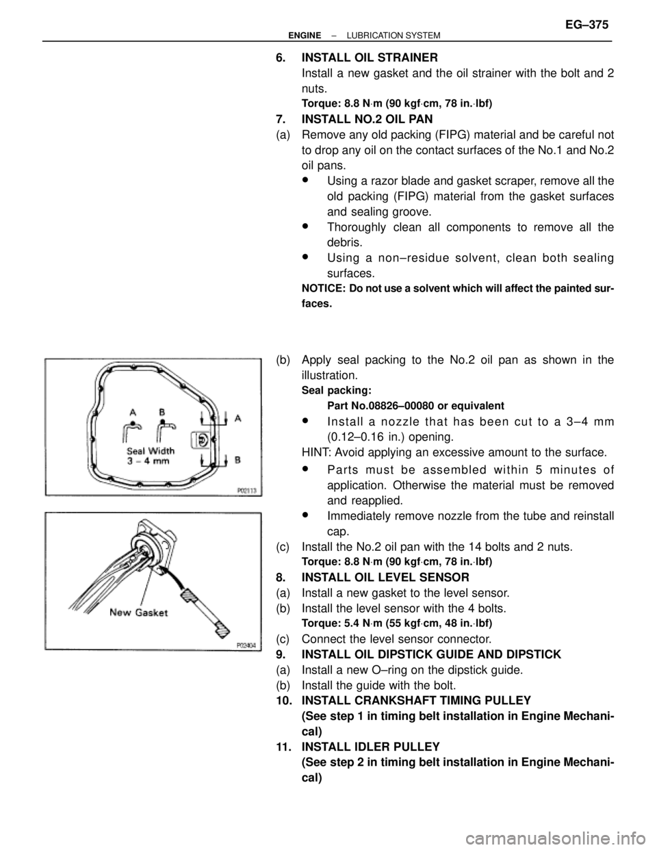
(b) Apply seal packing to the No.2 oil pan as shown in the
illustration.
Seal packing:
Part No.08826±00080 or equivalent
wInstall a nozzle that has been cut to a 3±4 mm
(0.12±0.16 in.) opening.
HINT: Avoid applying an excessive amount to the surface.
wParts must be assembled within 5 minutes of
application. Otherwise the material must be removed
and reapplied.
wImmediately remove nozzle from the tube and reinstall
cap.
(c) Install the No.2 oil pan with the 14 bolts and 2 nuts.
Torque: 8.8 NVm (90 kgfVcm, 78 in.Vlbf)
8. INSTALL OIL LEVEL SENSOR
(a) Install a new gasket to the level sensor.
(b) Install the level sensor with the 4 bolts.
Torque: 5.4 NVm (55 kgfVcm, 48 in.Vlbf)
(c) Connect the level sensor connector.
9. INSTALL OIL DIPSTICK GUIDE AND DIPSTICK
(a) Install a new O±ring on the dipstick guide.
(b) Install the guide with the bolt.
10. INSTALL CRANKSHAFT TIMING PULLEY
(See step 1 in timing belt installation in Engine Mechani-
cal)
11. INSTALL IDLER PULLEY
(See step 2 in timing belt installation in Engine Mechani-
cal)
± ENGINELUBRICATION SYSTEMEG±375
Page 1228 of 2543
12. 2JZ±GTE M/T:
INSTALL DRIVE BELT TENSIONER BRACKET
Torque: 27 NVm (280 kgfVcm, 20 ftVlbf)
13. INSTALL TIMING BELT
(See step 3 in timing belt installation in Engine Mechani-
cal)
14. 2JZ±GTE:
INSTALL CRANKSHAFT POSITION SENSOR
Torque: 8.8 NVm (90 kgfVcm, 78 in.Vlbf)
15. 2JZ±GTE:
INSTALL GENERATOR
16. REMOVE ENGINE STAND FROM ENGINE
17. ASSEMBLY ENGINE AND TRANSMISSION
(See components for engine removal & transmission
separation and assembly)
18. INSTALL ENGINE WITH TRANSMISSION
(See components for engine removal and installation)
OIL COOLER (2JZ±GTE)
COMPONENTS FOR REMOVAL AND
INSTALLATION
EG±376± ENGINELUBRICATION SYSTEM
Page 1229 of 2543
12. 2JZ±GTE M/T:
INSTALL DRIVE BELT TENSIONER BRACKET
Torque: 27 NVm (280 kgfVcm, 20 ftVlbf)
13. INSTALL TIMING BELT
(See step 3 in timing belt installation in Engine Mechani-
cal)
14. 2JZ±GTE:
INSTALL CRANKSHAFT POSITION SENSOR
Torque: 8.8 NVm (90 kgfVcm, 78 in.Vlbf)
15. 2JZ±GTE:
INSTALL GENERATOR
16. REMOVE ENGINE STAND FROM ENGINE
17. ASSEMBLY ENGINE AND TRANSMISSION
(See components for engine removal & transmission
separation and assembly)
18. INSTALL ENGINE WITH TRANSMISSION
(See components for engine removal and installation)
OIL COOLER (2JZ±GTE)
COMPONENTS FOR REMOVAL AND
INSTALLATION
EG±376± ENGINELUBRICATION SYSTEM
Page 1230 of 2543

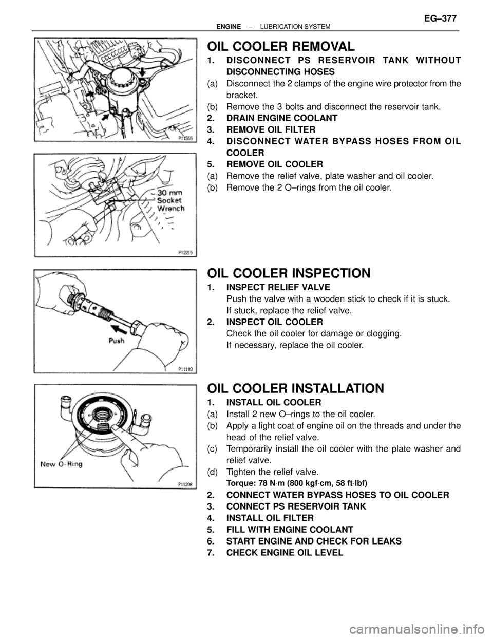
OIL COOLER REMOVAL
1. DISCONNECT PS RESERVOIR TANK WITHOUT
DISCONNECTING HOSES
(a) Disconnect the 2 clamps of the engine wire protector from the
bracket.
(b) Remove the 3 bolts and disconnect the reservoir tank.
2. DRAIN ENGINE COOLANT
3. REMOVE OIL FILTER
4. DISCONNECT WATER BYPASS HOSES FROM OIL
COOLER
5. REMOVE OIL COOLER
(a) Remove the relief valve, plate washer and oil cooler.
(b) Remove the 2 O±rings from the oil cooler.
OIL COOLER INSPECTION
1. INSPECT RELIEF VALVE
Push the valve with a wooden stick to check if it is stuck.
If stuck, replace the relief valve.
2. INSPECT OIL COOLER
Check the oil cooler for damage or clogging.
If necessary, replace the oil cooler.
OIL COOLER INSTALLATION
1. INSTALL OIL COOLER
(a) Install 2 new O±rings to the oil cooler.
(b) Apply a light coat of engine oil on the threads and under the
head of the relief valve.
(c) Temporarily install the oil cooler with the plate washer and
relief valve.
(d) Tighten the relief valve.
Torque: 78 NVm (800 kgfVcm, 58 ftVlbf)
2. CONNECT WATER BYPASS HOSES TO OIL COOLER
3. CONNECT PS RESERVOIR TANK
4. INSTALL OIL FILTER
5. FILL WITH ENGINE COOLANT
6. START ENGINE AND CHECK FOR LEAKS
7. CHECK ENGINE OIL LEVEL
± ENGINELUBRICATION SYSTEMEG±377
Page 1231 of 2543
OIL NOZZLE (2JZ±GTE)
COMPONENTS
OIL NOZZLES REMOVAL
1. REMOVE CRANKSHAFT
(See step 6 in cylinder block disassembly in Engine Me-
chanical)
2. REMOVE OIL NOZZLES (WITH RELIEF VALVES)
Using a 5 mm hexagon wrench, remove the bolt and oil
nozzle. Remove the 6 oil nozzles.
OIL NOZZLES INSPECTION
INSPECT RELIEF VALVES (OIL NOZZLES)
Push the valve with a wooden stick to check if it is stuck.
If stuck, replace the relief valve.
OIL NOZZLES INSTALLATION
1. INSTALL OIL NOZZLES (WITH RELIEF VALVES)
Using a 5 mm hexagon wrench, install the oil nozzle with the
bolt. Install the 6 oil nozzles.
Torque: 8.8 NVm (90 kgfVcm, 78 in.Vlbf)
2. INSTALL CRANKSHAFT
(See step 8 in cylinder block assembly in Engine Me-
chanical) EG±378
± ENGINELUBRICATION SYSTEM
Page 1232 of 2543

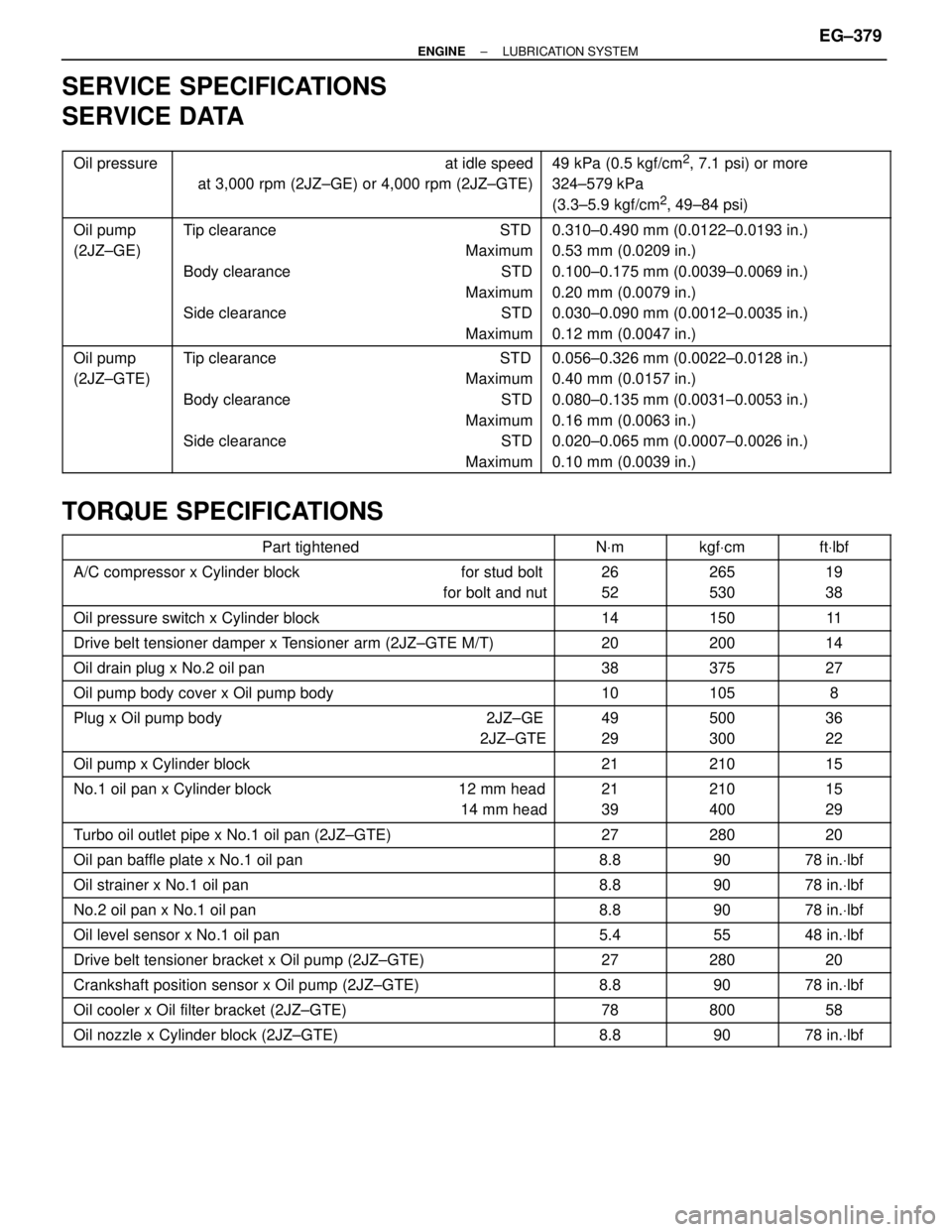
SERVICE SPECIFICATIONS
SERVICE DATA
������ �
����� �
����� ������
Oil pressure���������������� �
��������������� �
��������������� ����������������
at idle speed
at 3,000 rpm (2JZ±GE) or 4,000 rpm (2JZ±GTE)���������������� �
��������������� �
��������������� ����������������
49 kPa (0.5 kgf/cm2, 7.1 psi) or more
324±579 kPa
(3.3±5.9 kgf/cm
2, 49±84 psi)
������ �
����� �
����� �
����� �
����� ������
Oil pump
(2JZ±GE)���������������� �
��������������� �
��������������� �
��������������� �
��������������� ����������������
Tip clearance STD
Maximum
Body clearance STD
Maximum
Side clearance STD
Maximum���������������� �
��������������� �
��������������� �
��������������� �
��������������� ����������������
0.310±0.490 mm (0.0122±0.0193 in.)
0.53 mm (0.0209 in.)
0.100±0.175 mm (0.0039±0.0069 in.)
0.20 mm (0.0079 in.)
0.030±0.090 mm (0.0012±0.0035 in.)
0.12 mm (0.0047 in.)
������ �
����� �
����� �
����� �
����� ������
Oil pump
(2JZ±GTE)���������������� �
��������������� �
��������������� �
��������������� �
��������������� ����������������
Tip clearance STD
Maximum
Body clearance STD
Maximum
Side clearance STD
Maximum���������������� �
��������������� �
��������������� �
��������������� �
��������������� ����������������
0.056±0.326 mm (0.0022±0.0128 in.)
0.40 mm (0.0157 in.)
0.080±0.135 mm (0.0031±0.0053 in.)
0.16 mm (0.0063 in.)
0.020±0.065 mm (0.0007±0.0026 in.)
0.10 mm (0.0039 in.)
TORQUE SPECIFICATIONS
���������������������� ����������������������Part tightened����� �����NVm������ ������kgfVcm������ ������ftVlbf
���������������������� �
��������������������� ����������������������
A/C compressor x Cylinder block for stud bolt
for bolt and nut����� �
���� �����
26
52������ �
����� ������
265
530������ �
����� ������
19
38
���������������������� ����������������������Oil pressure switch x Cylinder block����� �����14������ ������150������ ������11
���������������������� ����������������������Drive belt tensioner damper x Tensioner arm (2JZ±GTE M/T)����� �����20������ ������200������ ������14
���������������������� ����������������������Oil drain plug x No.2 oil pan����� �����38������ ������375������ ������27
���������������������� ����������������������Oil pump body cover x Oil pump body����� �����10������ ������105������ ������8
���������������������� �
��������������������� ����������������������
Plug x Oil pump body 2JZ±GE
2JZ±GTE����� �
���� �����
49
29������ �
����� ������
500
300������ �
����� ������
36
22
���������������������� ����������������������Oil pump x Cylinder block����� �����21������ ������210������ ������15
���������������������� �
��������������������� ����������������������
No.1 oil pan x Cylinder block 12 mm head
14 mm head����� �
���� �����
21
39������ �
����� ������
210
400������ �
����� ������
15
29
���������������������� ����������������������Turbo oil outlet pipe x No.1 oil pan (2JZ±GTE)����� �����27������ ������280������ ������20
���������������������� ����������������������Oil pan baffle plate x No.1 oil pan����� �����8.8������ ������90������ ������78 in.Vlbf
���������������������� ����������������������Oil strainer x No.1 oil pan����� �����8.8������ ������90������ ������78 in.Vlbf
���������������������� ����������������������No.2 oil pan x No.1 oil pan����� �����8.8������ ������90������ ������78 in.Vlbf
���������������������� ����������������������Oil level sensor x No.1 oil pan����� �����5.4������ ������55������ ������48 in.Vlbf
���������������������� ����������������������Drive belt tensioner bracket x Oil pump (2JZ±GTE)����� �����27������ ������280������ ������20���������������������� ����������������������Crankshaft position sensor x Oil pump (2JZ±GTE)����� �����8.8������ ������90������ ������78 in.Vlbf���������������������� ����������������������Oil cooler x Oil filter bracket (2JZ±GTE)����� �����78������ ������800������ ������58���������������������� ����������������������Oil nozzle x Cylinder block (2JZ±GTE)����� �����8.8������ ������90������ ������78 in.Vlbf
± ENGINELUBRICATION SYSTEMEG±379
Page 1233 of 2543
±MEMO± EG±380
± ENGINELUBRICATION SYSTEM
Page 1234 of 2543
MAINTENANCE
GENERAL NOTES:
wThere are two separate maintenance schedules,
namely A and B, which apply to different driving
conditions. Find out how the vehicle is driven, select the
appropriate schedule and service the vehicle
accordingly.
wEvery service item in the periodic maintenance list must
be performed.
wNext to the columns of periods in the schedule,
reference pages have been added for easy access to
service data and procedures necessary for each
operation.
wThe service interval for scheduled maintenance is
determined by the odometer reading or time interval,
whichever comes first, shown in the schedule.
wMaintenance services after the last period should be
performed at the same interval as before unless
otherwise noted.
wSkipping even one item in the list can cause the engine
to run poorly and increase exhaust emissions.
MA±1