Page 422 of 2543

CHECK TERMINAL TT OUTPUT
VOLTAGE
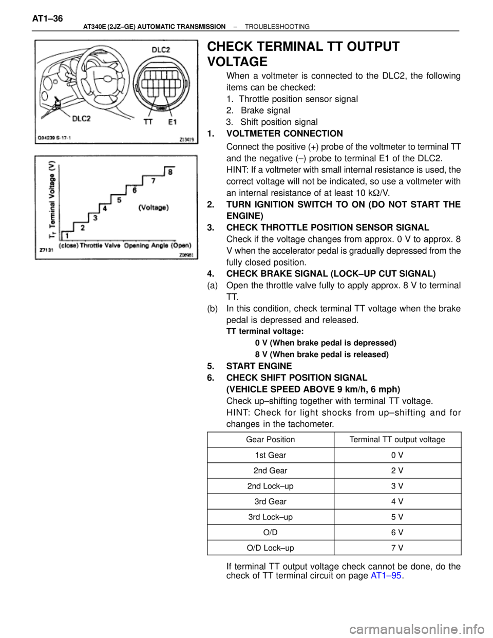
When a voltmeter is connected to the DLC2, the following
items can be checked:
1. Throttle position sensor signal
2. Brake signal
3. Shift position signal
1. VOLTMETER CONNECTION
Connect the positive (+) probe of the voltmeter to terminal TT
and the negative (±) probe to terminal E1 of the DLC2.
HINT: If a voltmeter with small internal resistance is used, the
correct voltage will not be indicated, so use a voltmeter with
an internal resistance of at least 10 k�/V.
2. TURN IGNITION SWITCH TO ON (DO NOT START THE
ENGINE)
3. CHECK THROTTLE POSITION SENSOR SIGNAL
Check if the voltage changes from approx. 0 V to approx. 8
V when the accelerator pedal is gradually depressed from the
fully closed position.
4. CHECK BRAKE SIGNAL (LOCK±UP CUT SIGNAL)
(a) Open the throttle valve fully to apply approx. 8 V to terminal
TT.
(b) In this condition, check terminal TT voltage when the brake
pedal is depressed and released.
TT terminal voltage:
0 V (When brake pedal is depressed)
8 V (When brake pedal is released)
5. START ENGINE
6. CHECK SHIFT POSITION SIGNAL
(VEHICLE SPEED ABOVE 9 km/h, 6 mph)
Check up±shifting together with terminal TT voltage.
HINT: Check for light shocks from up±shifting and for
changes in the tachometer.
����������� �
���������� �����������Gear Position
������������ �
����������� ������������Terminal TT output voltage
�����������1st Gear0V����������� �����������1st Gear0 V
�����������2nd Gear2V����������� �����������2nd Gear2 V
����������� �����������2nd Lock up3V�����������2nd Lock±up3 V����������� �����������
3rd Gear4V����������� �����������3rd Gear4 V
�����������3rd Lock up5V����������� �����������3rd Lock±up5 V
�����������O/D6V����������� �����������O/D6 V
����������� �����������O/D Lock up7V�����������O/D Lock±up7 V
If terminal TT output voltage check cannot be done, do the
check of TT terminal circuit on page AT1±95. AT1±36
± AT340E (2JZ±GE) AUTOMATIC TRANSMISSIONTROUBLESHOOTING
Page 461 of 2543

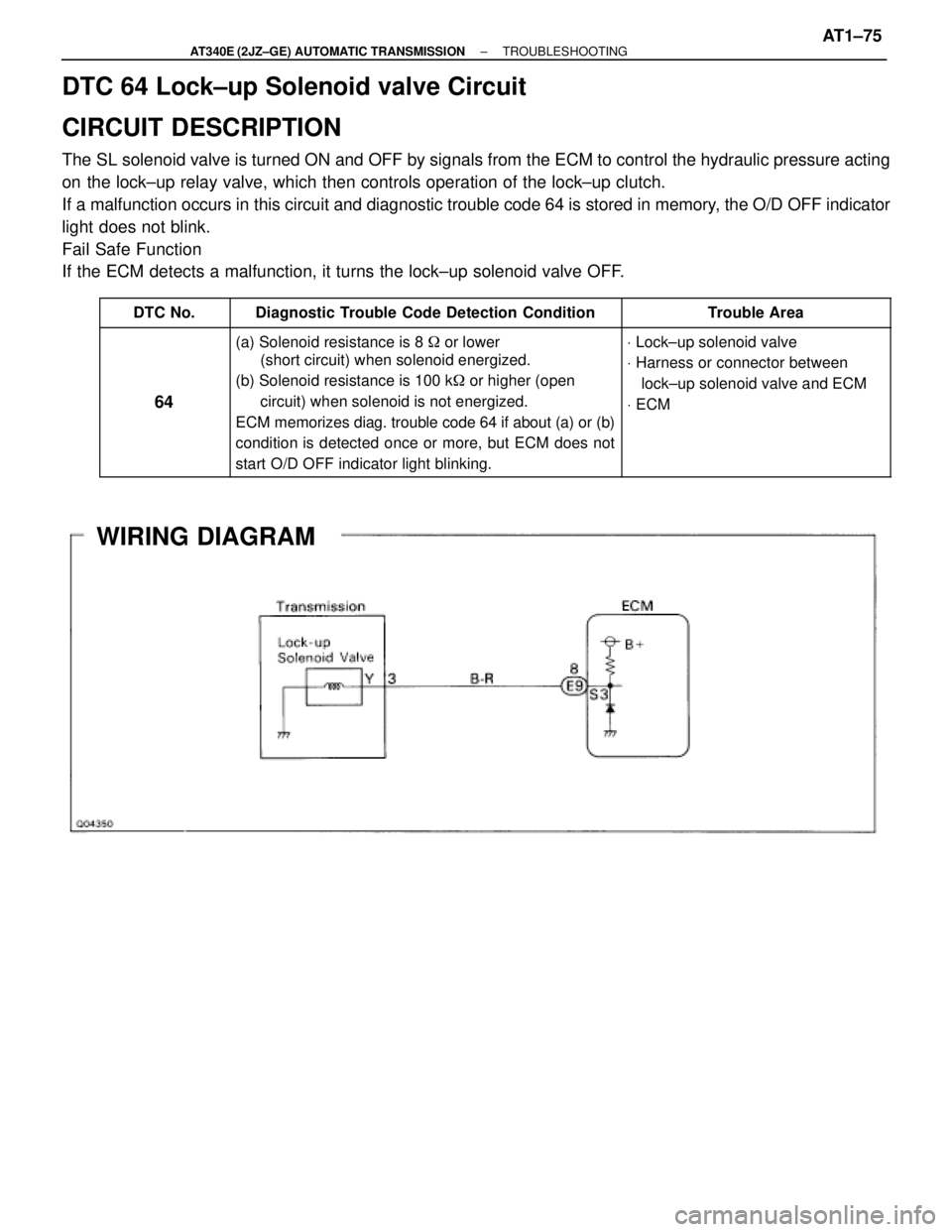
DTC 64 Lock±up Solenoid valve Circuit
CIRCUIT DESCRIPTION
The SL solenoid valve is turned ON and OFF by signals from the ECM to control the hydraulic pressure acting
on the lock±up relay valve, which then controls operation of the lock±up clutch.
If a malfunction occurs in this circuit and diagnostic trouble code 64 is stored in memory, the O/D OFF indicator
light does not blink.
Fail Safe Function
If the ECM detects a malfunction, it turns the lock±up solenoid valve OFF.
������ ������DTC No.����������������� �����������������Diagnostic Trouble Code Detection Condition������������ ������������Trouble Area
������ �
����� �
����� �
����� �
����� �
����� ������
64
����������������� �
���������������� �
���������������� �
���������������� �
���������������� �
���������������� �����������������
(a) Solenoid resistance is 8 � or lower
(short circuit) when solenoid energized.
(b) Solenoid resistance is 100 k� or higher (open
circuit) when solenoid is not energized.
ECM memorizes diag. trouble code 64 if about (a) or (b)
condition is detected once or more, but ECM does not
start O/D OFF indicator light blinking.������������
������������
������������
������������
������������
������������ ������������
V Lock±up solenoid valve
V Harness or connector between
lock±up solenoid valve and ECM
V ECM
WIRING DIAGRAM
± AT340E (2JZ±GE) AUTOMATIC TRANSMISSIONTROUBLESHOOTINGAT1±75
Page 464 of 2543
INSPECTION PROCEDURE
(See page EG±219).
Turn ignition switch ON.
Do not depress the brake pedal during this test.
The voltage will stay at 0 V if depressed.
Voltage changes from 0 V to 8 V by stages.
Check throttle position signal.
Check voltage at the terminal TT of the DLC2
while gradually depressing the accelerator pedal
from the fully closed position to the fully opened
position.
Proceed to next circuit inspection shown on
matrix chart (See page AT1±58).
Replace throttle position sensor.
Repair or replace harness or connector.
Check and replace ECM.
Check harness and connector between ECM and throttle position sen-
sor (See page IN±30).
AT1±78± AT340E (2JZ±GE) AUTOMATIC TRANSMISSIONTROUBLESHOOTING
Page 465 of 2543
Kick±down Switch Circuit
CIRCUIT DESCRIPTION
The kick±down switch is turned on when the accelerator pedal
is depressed beyond the full throttle opening and sends signals
to ECM.
When the kick±down switch is turned on, the ECM controls gear
shifting according to the programmed shift diagrams.
If a short circuit develops in the kick±down switch, the ECM dis-
regards the kick±down signals and controls shifting at the nor-
mal shift points.
WIRING DIAGRAM
± AT340E (2JZ±GE) AUTOMATIC TRANSMISSIONTROUBLESHOOTINGAT1±79
Page 470 of 2543
Connect a voltmeter to the terminals TT and
E1 of the DLC2.
Turn ignition switch ON (Do not start the en-
gine).
Fully depress the accelerator pedal until the
voltmeter indicates 8 V and hold it.
Depress and release the brake pedal and
check the voltage.
Check stop light signal.
Brake pedal
Proceed to next circuit inspection shown on
matrix chart (See page AT1±58).
Check harness and connector between ECM and stop light switch
(See page IN±30).
Repair or replace harness or connector
Voltage
Depressed0 V
Released8 V
Check and replace ECM. AT1±84
± AT340E (2JZ±GE) AUTOMATIC TRANSMISSIONTROUBLESHOOTING
Page 472 of 2543

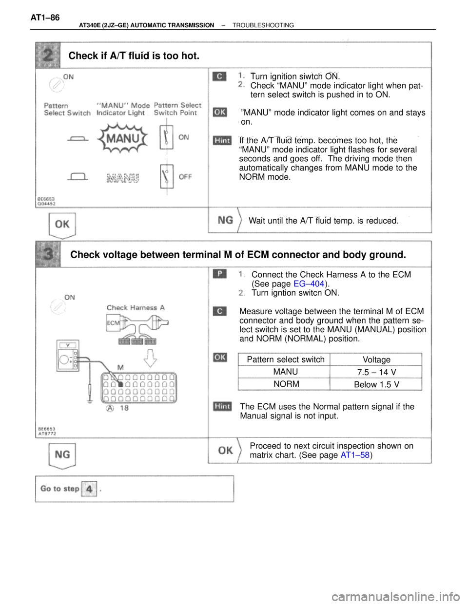
Turn ignition siwtch ON.
Check ªMANUº mode indicator light when pat-
tern select switch is pushed in to ON.
Check if A/T fluid is too hot.
Pattern select switch
Connect the Check Harness A to the ECM
(See page EG±404).
Turn igntion switcn ON.
Check voltage between terminal M of ECM connector and body ground.
Proceed to next circuit inspection shown on
matrix chart. (See page AT1±58)
Voltage
MANU7.5 ± 14 V
NORMBelow 1.5 V
Wait until the A/T fluid temp. is reduced.
The ECM uses the Normal pattern signal if the
Manual signal is not input.
Measure voltage between the terminal M of ECM
connector and body ground when the pattern se-
lect switch is set to the MANU (MANUAL) position
and NORM (NORMAL) position.
ºMANUº mode indicator light comes on and stays
on.
If the A/T fluid temp. becomes too hot, the
ªMANUº mode indicator light flashes for several
seconds and goes off. The driving mode then
automatically changes from MANU mode to the
NORM mode. AT1±86
± AT340E (2JZ±GE) AUTOMATIC TRANSMISSIONTROUBLESHOOTING
Page 477 of 2543
O D Cancel Signal Circuit
CIRCUIT DESCRIPTION
While driving with cruise control activated, in order to minimize gear shifting and provide smooth uphill cruising,
overdrive may be prohibited temporarily in some conditions.
The Cruise Control ECU sends O/D cut signals to the ECM as necessary and the ECM cancels overdrive shifting
until these signals are discontinued.
(For details, see the cruise control section, page BE±162)
WIRING DIAGRAM
INSPECTION PROCEDURE
Connect the Check Harness A to the ECM
(See page EG±404).
Turn ignition switch ON.
Check and replace ECM.
Check voltage between terminal OD1 of ECM connector and body ground.
Measure voltage between terminal OD1 of ECM
connector and body ground.
Proceed to next circuit inspection shown on
matrix chart (See page AT1±58).
Voltage: 4 ± 6 V
± AT340E (2JZ±GE) AUTOMATIC TRANSMISSIONTROUBLESHOOTINGAT1±91
Page 490 of 2543

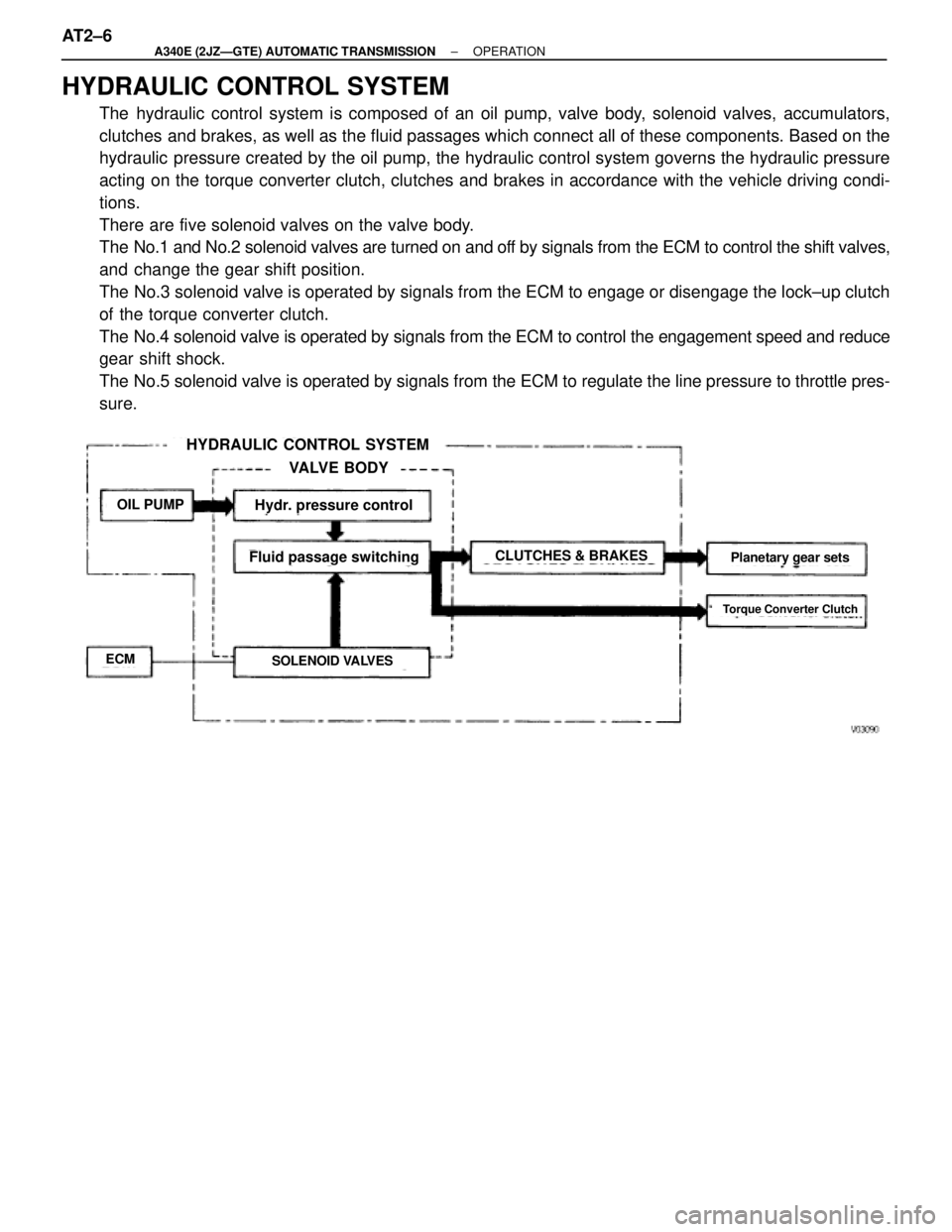
HYDRAULIC CONTROL SYSTEM
The hydraulic control system is composed of an oil pump, valve body, solenoid valves, accumulators,
clutches and brakes, as well as the fluid passages which connect all of these components. Based on the
hydraulic pressure created by the oil pump, the hydraulic control system governs the hydraulic pressure
acting on the torque converter clutch, clutches and brakes in accordance with the vehicle driving condi-
tions.
There are five solenoid valves on the valve body.
The No.1 and No.2 solenoid valves are turned on and off by signals from the ECM to control the shift valves,
and change the gear shift position.
The No.3 solenoid valve is operated by signals from the ECM to engage or disengage the lock±up clutch
of the torque converter clutch.
The No.4 solenoid valve is operated by signals from the ECM to control the engagement speed and reduce
gear shift shock.
The No.5 solenoid valve is operated by signals from the ECM to regulate the line pressure to throttle pres-
sure.
HYDRAULIC CONTROL SYSTEM
VALVE BODY
OIL PUMP
ECMSOLENOID VALVES
CLUTCHES & BRAKES
Hydr. pressure control
Fluid passage switchingPlanetary gear sets
Torque Converter Clutch
AT2±6± A340E (2JZÐGTE) AUTOMATIC TRANSMISSIONOPERATION