Page 2027 of 2543
 Remove ignition coil. (See page IG±26)
(2) Remove spark plug.
(3) Install the spark plug to the ignition coil, and connect
the ignition coil connector.
(4) Ground the spark plug.")
Check for spark.
(1) Remove ignition coil. (See page IG±26)
(2) Remove spark plug.
(3) Install the spark plug to the ignition coil, and connect
the ignition coil connector.
(4) Ground the spark plug.
Check if spark occurs while engine is being cranked.
To prevent excess fuel being injected from injectors dur-
ing this test, don't crank the engine for more than 1Ð2
seconds at a time.
Check for open and short in harness and connector in IGF signal circuit
between engine control module and igniter (See page IN±30).
Repair or replace harness or connector.
Replace igniter.
Check and replace engine control module.
Disconnect igniter connector and check voltage between terminal IGF of
engine control module connector and body ground.
(1) Disconnect igniter connector.
(2) Connect SST (check harness ªAº).
(See page EG±510)
SST 09990±01000
(3) Turn ignition switch ON.
Measure voltage between terminal IGF of engine con-
trol module connector and body ground.
Voltage: 4.5 Ð 5.5 V
INSPECTION PROCEDURE
EG±520± ENGINE2JZ±GTE ENGINE TROUBLESHOOTING
Page 2028 of 2543
(See page EG±510)
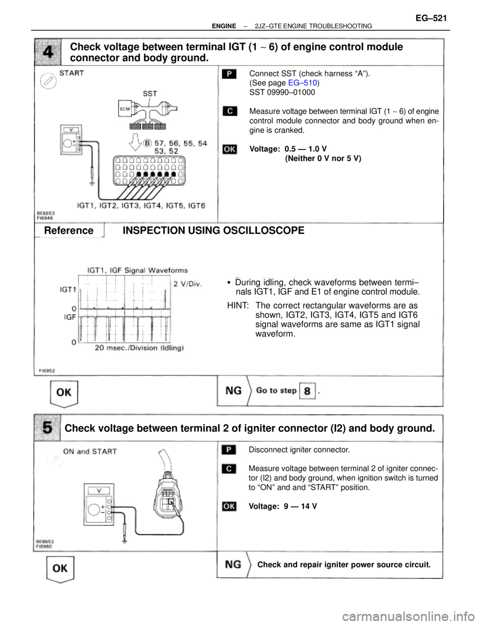
�During idling, check waveforms between termi±
nals IGT1, IGF and E1 of engine control module.
HINT: The correct rectangular waveforms are as
shown, IGT2, IGT3, IGT4, IGT5 and IGT6
signal waveforms are same as IGT1 signal
waveform.
Check voltage between terminal IGT (1 ~ 6) of engine control module
connector and body ground.
Connect SST (check harness ªAº).
(See page EG±510)
SST 09990±01000
Measure voltage between terminal IGT (1 ~ 6) of engine
control module connector and body ground when en-
gine is cranked.
Voltage: 0.5 Ð 1.0 V
(Neither 0 V nor 5 V)
Check voltage between terminal 2 of igniter connector (I2) and body ground.
Disconnect igniter connector.
Measure voltage between terminal 2 of igniter connec-
tor (I2) and body ground, when ignition switch is turned
to ªONº and and ªSTARTº position.
Voltage: 9 Ð 14 V
Check and repair igniter power source circuit.
ReferenceINSPECTION USING OSCILLOSCOPE
± ENGINE2JZ±GTE ENGINE TROUBLESHOOTINGEG±521
Page 2071 of 2543

See page EG±503.
CIRCUIT DESCRIPTION
The EGR system is designed to recirculate the exhaust gas, controlled according to the driving condi-
tions back into the intake air±fuel mixture. It helps to slow down combustion in the cylinder and thus
lower the combustion temperature which, in turn, reduces the amount of NO
x emission. The amount
of EGR is regulated by the EGR vacuum modulator according to the engine load.
If even one of the following conditions is fulfilled,
the VSV is turned ON by a signal from the ECM.
This resists in atmospheric air acting on the EGR
valve, closing the EGR valve and shutting off the
exhaust gas (EGR cut±OFF).
� Engine coolant temp. below 50°C (122°F)
� During deceleration (throttle valve closed)
� Light engine load (amount of intake air very
small)
� Engine speed over 4,800 rpm
� Manifold absolute pressure more than 120 kPa
(1.2 kgf/cm
2, 17.4 psi)
DTC No.Diagnostic Trouble Code Detecting ConditionTrouble Area
No No.1 knock sensor signal to ECM for 4
crank revolutions with engine speed between
2,050 rpm and 5,950 rpm
�Open EGR gas temp. sensor circuit
�Short in VSV circuit for EGR
�EGR hose disconnected, valve stuck
�Clogged EGR gas passage
�ECM
EGR gas temp. and intake air temp. are
60°C(140°F) or less for A/T, 55°C (131°F) or
less for M/T for 1 ~ 4 min. under conditions (a)
and (b):
(2 trip detection logic)*
(a) Engine coolant temp.: 60°C (140°F) or
more
(b) EGR operation possible (Example A/T in
3rd speed (5th for M/T), A/C ON, 96 km/h
(60 mph), Flat road)
Purpose of the driving pattern.
(a) To simulate diagnostic trouble code detecting condition after diagnostic trouble code is recorded.
(b) To check that the malfunction is corrected when the repair is completed by confirming that diagnos±
tic trouble code is no longer detected.
DIAGNOSTIC TROUBLE CODE DETECTION DRIVING PATTERN
DTC 71 EGR System Malfunction
EG±564± ENGINE2JZ±GTE ENGINE TROUBLESHOOTING
Page 2079 of 2543
.
Setting the test mode.
(1) Turn ignition switch OFF.
(2) Connect terminals TE2 and E1 of DLC2.
(3) Turn ignition switch ON.
(For chec")
INSPECTION PROCEDURE
PNP...Go to page EG±574.
(See page EG±514).
Setting the test mode.
(1) Turn ignition switch OFF.
(2) Connect terminals TE2 and E1 of DLC2.
(3) Turn ignition switch ON.
(For checking terminal IDL, disconnect the
vacuum hose from the throttle body, then ap-
ply vacuum to the throttle opener (See page
EG±292)).
((For checking terminal A/C, start the engine.)
(4) connect terminals TE1 and E1 of DLC2.
Check if code ª51º is output by the malfunction indi-
cator lamp.
*: Before the STA signal is input (ST is not ON), diag±
nostic trouble code 43 is also output.
Diagnostic trouble code 42 is output with vehicle speed
5 km/h (3 mph) or below.
Check output condition of diagnostic trouble code 51.
IDL1...Go to step [2].
PNP....Go to page Eg±574.
A/C....Go to step [3].
Proceed to next circuit inspection shown on matrix
chart (See page Eg±514).
Check output condition of diagnostic trouble code 51.
Throttle Position
Sensor (IDL1)
Condition
Park/Neutral Posi-
tion Switch (PNP)
Code
Accelerator pedal
released
Accelerator pedal
depressed
A/C SW ON
A/C SW OFFA/C Switch (A/C)
P or N position
R, D, 2 or L position
EG±572± ENGINE2JZ±GTE ENGINE TROUBLESHOOTING
Page 2083 of 2543
ECM Power Source Circuit
CIRCUIT DESCRIPTION
When the ignition switch is turned on, battery volt-
age is applied to the terminal IGSW of the ECM,
and the main relay control circuit in the ECM sends
a signal to the terminal M±REL of the ECM, switch-
ing on the main relay. This signal causes current to
flow to the coil, closing the contacts of the main
relay and supplying power to the terminal + B of the
ECM.
If the ignition switch is turned off, the ECM contin-
ues to switch on the main relay for a maximum of
2 seconds for the initial setting of the IAC valve. EG±576
± ENGINE2JZ±GTE ENGINE TROUBLESHOOTING
Page 2093 of 2543
CIRCUIT DESCRIPTION
The IAC valve is situated on the intake air chamber In-
take air bypassing the throttle valve is directed to the
IAC valve through a passage.
A step motor is built into the IAC valve. It consists of 4
coils, a magnetic rotor, valve shaft and a valve.
When the current flows to the coils due to signals from
the ECM, the rotor turns and moves the valve shaft for-
ward or backward, changing the clearance between
the valve and the valve seat.
In this way the intake air volume bypassing the throttle
valve is regulated, controlling the engine speed.
There are 125 possible positions to which the valve can
be opened.
�With the engine idling measure wave forms
between terminals ISC1, ISC2, ISC3,
ISC4 and E01 of engine control module
when A/C switch ON or OFF.
HINT:
The correct waveforms are as shown.
INSPECTION USING OSCILLOSCOPEReference
IAC Valve Circuit
EG±586± ENGINE2JZ±GTE ENGINE TROUBLESHOOTING