Page 520 of 2543

CHECK TERMINAL TT OUTPUT
VOLTAGE
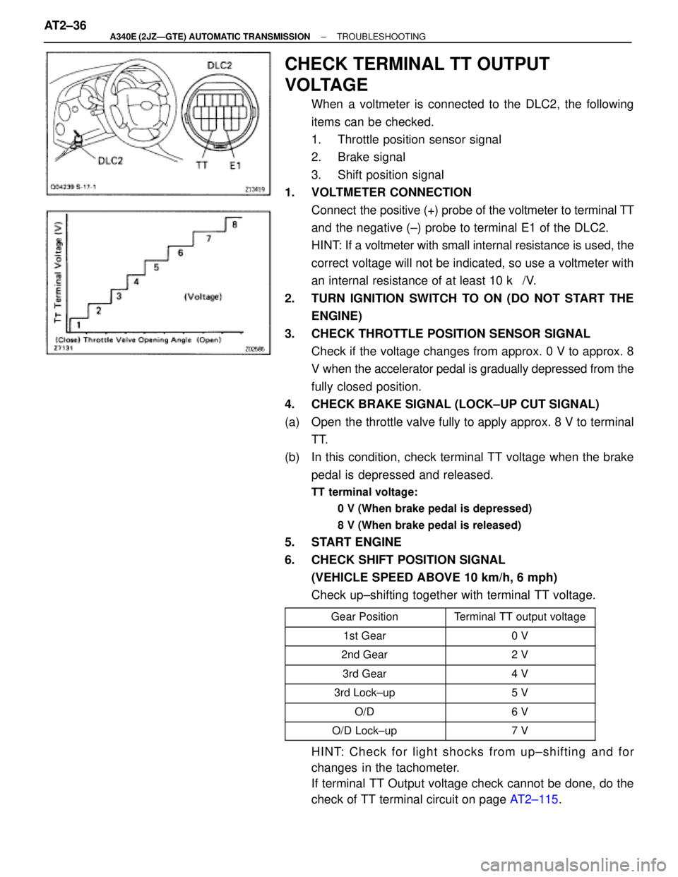
When a voltmeter is connected to the DLC2, the following
items can be checked.
1. Throttle position sensor signal
2. Brake signal
3. Shift position signal
1. VOLTMETER CONNECTION
Connect the positive (+) probe of the voltmeter to terminal TT
and the negative (±) probe to terminal E1 of the DLC2.
HINT: If a voltmeter with small internal resistance is used, the
correct voltage will not be indicated, so use a voltmeter with
an internal resistance of at least 10 k�/V.
2. TURN IGNITION SWITCH TO ON (DO NOT START THE
ENGINE)
3. CHECK THROTTLE POSITION SENSOR SIGNAL
Check if the voltage changes from approx. 0 V to approx. 8
V when the accelerator pedal is gradually depressed from the
fully closed position.
4. CHECK BRAKE SIGNAL (LOCK±UP CUT SIGNAL)
(a) Open the throttle valve fully to apply approx. 8 V to terminal
TT.
(b) In this condition, check terminal TT voltage when the brake
pedal is depressed and released.
TT terminal voltage:
0 V (When brake pedal is depressed)
8 V (When brake pedal is released)
5. START ENGINE
6. CHECK SHIFT POSITION SIGNAL
(VEHICLE SPEED ABOVE 10 km/h, 6 mph)
Check up±shifting together with terminal TT voltage.
����������� �����������Gear Position��������� ���������Terminal TT output voltage����������� �����������1st Gear��������� ���������0 V����������� �
���������� �����������2nd Gear
��������� �
�������� ���������2 V
����������� �����������3rd Gear��������� ���������4 V
����������� �����������3rd Lock±up��������� ���������5 V
����������� �����������O/D��������� ���������6 V
����������� �����������O/D Lock±up��������� ���������7 V
HINT: Check for light shocks from up±shifting and for
changes in the tachometer.
If terminal TT Output voltage check cannot be done, do the
check of TT terminal circuit on page AT2±115. AT2±36
± A340E (2JZÐGTE) AUTOMATIC TRANSMISSIONTROUBLESHOOTING
Page 582 of 2543
INSPECTION PROCEDURE
Check main throttle position signal.
Voltage changes from 0 V to 8 V by stages.
Turn ignition switch ON.
Do not depress the brake pedal during the test. The
voltage will stay at 0 V if depressed.
Check voltage at the terminal TT of the DLC2 while
gradually depressing the accelerator pedal from
the fully closed position to the fully opened position.
(Close) Throttle Valve Opening Angle (Open)
Proceed to next circuit inspection shown on
matrix chart (See page AT2±64).
Replace throttle position sensor.
Repair or replace harness or connector.
Check main (sub)±throttle position sensor. (see page EG±292, 293)
Check harness and connector between ECM and Main (Sub)±throttle
position sensor (See page IN±30).
Check and replace ECM.
AT2±98± A340E (2JZÐGTE) AUTOMATIC TRANSMISSIONTROUBLESHOOTING
Page 583 of 2543
Kick±down Switch Circuit
The kick±down switch is turned on when the accelerator pedal
is depressed beyond the full throttle opening and sends signals
to ECM.
When the kick±down switch is turned on, the ECM controls
gear shifting according to the programmed shift diagrams.
If a short circuit develops in the kick±down switch, the ECM dis-
regards the kick±down signals and controls shifting at the nor-
mal shift points.
CIRCUIT DESCRIPTION
± A340E (2JZÐGTE) AUTOMATIC TRANSMISSIONTROUBLESHOOTINGAT2±99
Page 588 of 2543
Depressed
Released
Brake pedalVoltage
0 V
8 V
Check stop light signal.
1. Connect the voltmeter to the terminals TT and
E1 of the DLC2.
2. Turn ignition switch ON.
3. Fully depress the accelerator pedal until the
voltmeter indicates 8 V and hold it.
4. Depress and release the brake pedal and
check the voltage.
Proceed to next circuit inspection shown on
matrix chart (See page AT2±64).
Check operation of stop light.
Repair or replace harness or connector.
Check and replace ECM.
Check harness and connector between ECM and stop light switch (See page
IN±30).
Check and repair stop light circuit.
Check if the stop lights go on and off normally when the brake pedal is depressed and released.
INSPECTION PROCEDURE
AT2±104± A340E (2JZÐGTE) AUTOMATIC TRANSMISSIONTROUBLESHOOTING
Page 590 of 2543

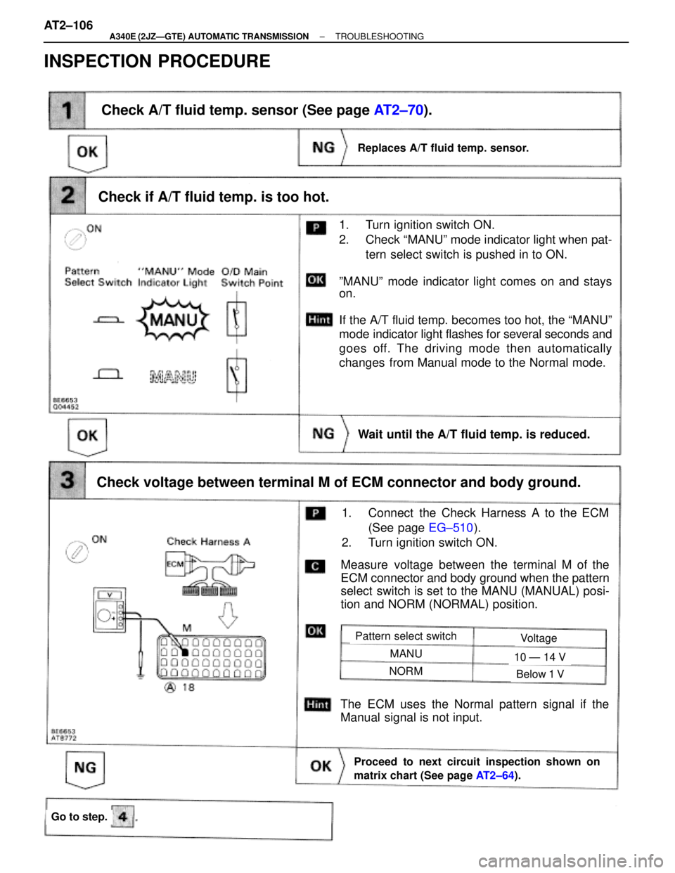
Check if A/T fluid temp. is too hot.
1. Turn ignition switch ON.
2. Check ªMANUº mode indicator light when pat-
tern select switch is pushed in to ON.
ºMANUº mode indicator light comes on and stays
on.
If the A/T fluid temp. becomes too hot, the ªMANUº
mode indicator light flashes for several seconds and
goes off. The driving mode then automatically
changes from Manual mode to the Normal mode.
Measure voltage between the terminal M of the
ECM connector and body ground when the pattern
select switch is set to the MANU (MANUAL) posi-
tion and NORM (NORMAL) position.
Check A/T fluid temp. sensor (See page AT2±70).
Check voltage between terminal M of ECM connector and body ground.
Replaces A/T fluid temp. sensor.
1. Connect the Check Harness A to the ECM
(See page EG±510).
2. Turn ignition switch ON.
Proceed to next circuit inspection shown on
matrix chart (See page AT2±64).
The ECM uses the Normal pattern signal if the
Manual signal is not input.
Pattern select switchVoltage
MANU
NORM
10 Ð 14 V
Below 1 V
Go to step.
Wait until the A/T fluid temp. is reduced.
INSPECTION PROCEDURE
AT2±106± A340E (2JZÐGTE) AUTOMATIC TRANSMISSIONTROUBLESHOOTING
Page 595 of 2543
Check voltage between terminal OD1 of ECM connector and body ground.
Measure voltage between terminal OD1 of ECM
connector and body ground.
Voltage: 4 Ð 6 V
Connect the Check Harness A to the ECM
Turn ignition switch ON.
Proceed to next circuit inspection shown on ma-
trix chart (See page AT2±64).
O D Cancel Signal Circuit
CIRCUIT DESCRIPTION
While driving with cruise control activated, in order to minimize gear shifting and provide smooth up±hill
cruising, overdrive may be prohibited temporarily in some conditions.
The Cruise Control ECU sends O/D cut signals to the ECM as necessary and the ECM cancels overdrive
shifting until these signals are discontinued.
(For details see the cruise control section, page BE±162)
INSPECTION PROCEDURE
± A340E (2JZÐGTE) AUTOMATIC TRANSMISSIONTROUBLESHOOTINGAT2±111
Page 605 of 2543

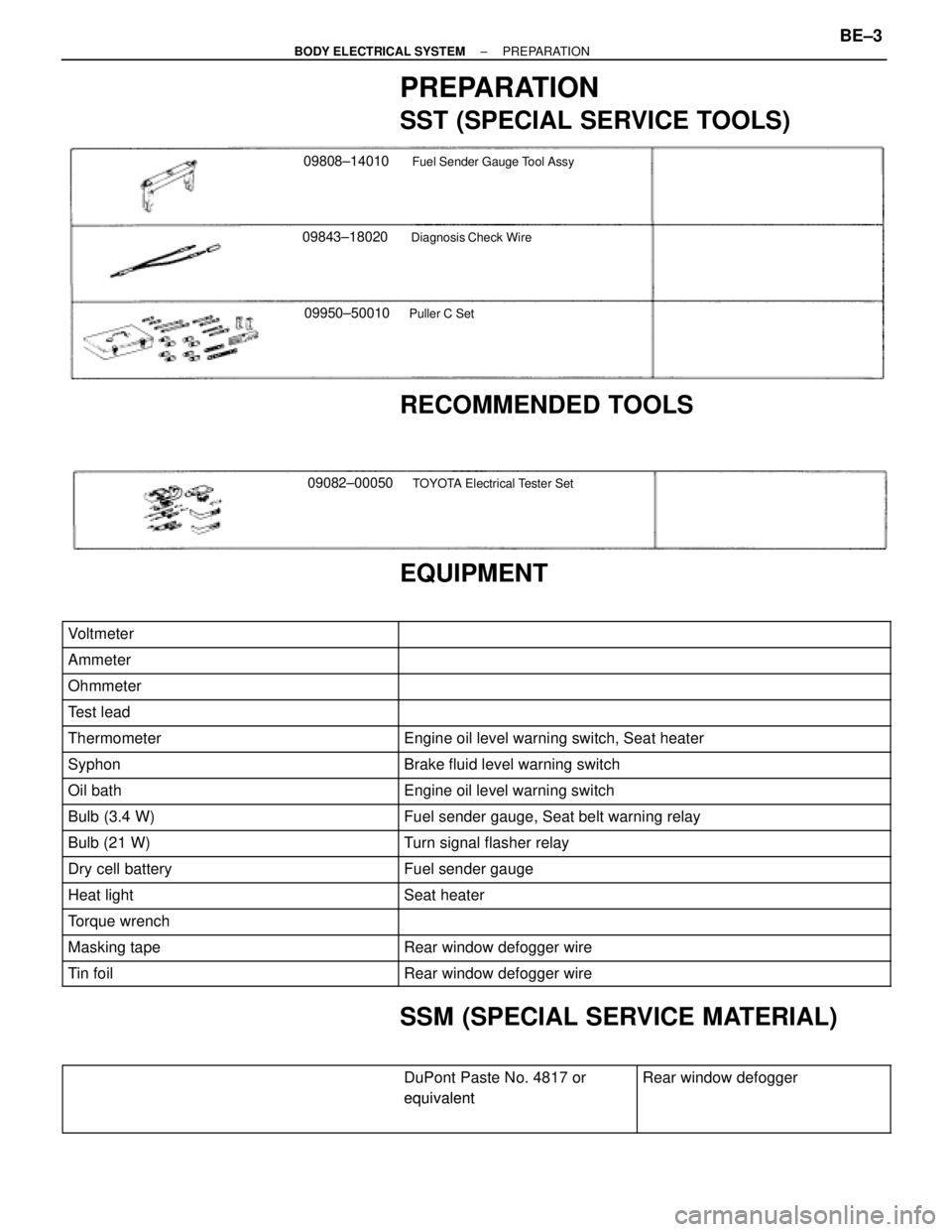
PREPARATION
SST (SPECIAL SERVICE TOOLS)
09843±18020Diagnosis Check Wire
09808±14010Fuel Sender Gauge Tool Assy
09950±50010Puller C Set
RECOMMENDED TOOLS
09082±00050TOYOTA Electrical Tester Set
�
EQUIPMENT
��������������� �
�������������� ���������������Voltmeter
���������������������� �
��������������������� ����������������������
��������������� ���������������Ammeter���������������������� ����������������������
��������������� ���������������Ohmmeter���������������������� ����������������������
��������������� ���������������Test lead���������������������� ����������������������
��������������� ���������������Thermometer���������������������� ����������������������Engine oil level warning switch, Seat heater
��������������� ���������������Syphon���������������������� ����������������������Brake fluid level warning switch
��������������� ���������������Oil bath���������������������� ����������������������Engine oil level warning switch
��������������� ���������������Bulb (3.4 W)���������������������� ����������������������Fuel sender gauge, Seat belt warning relay��������������� ���������������Bulb (21 W)���������������������� ����������������������Turn signal flasher relay��������������� ���������������Dry cell battery���������������������� ����������������������Fuel sender gauge��������������� �
�������������� ���������������Heat light
���������������������� �
��������������������� ����������������������Seat heater
��������������� ���������������Torque wrench���������������������� ����������������������
��������������� ���������������Masking tape���������������������� ����������������������Rear window defogger wire
��������������� ���������������Tin foil���������������������� ����������������������Rear window defogger wire
SSM (SPECIAL SERVICE MATERIAL)
������������������������� �
������������������������
DuPont Paste No. 4817 or
equivalent
������������ �
�����������
Rear window defogger
������������������������� �
������������������������ �������������������������
equivalent������������ �
����������� ������������
± BODY ELECTRICAL SYSTEMPREPARATIONBE±3
Page 622 of 2543
TURN SIGNAL AND HAZARD
WARNING SYSTEM
PARTS LOCATION
BE±20± BODY ELECTRICAL SYSTEMTURN SIGNAL AND HAZARD WARNING SYSTEM