Page 396 of 2543
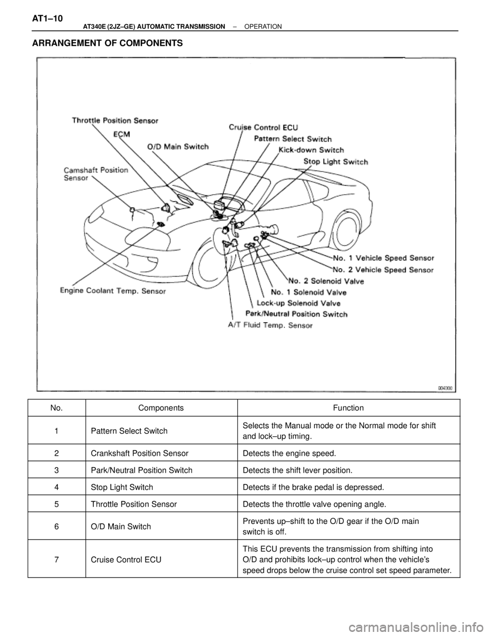
ARRANGEMENT OF COMPONENTS
����� �����No.�������������� ��������������Components������������������� �������������������Function
����� �����
1Pattern Select Switch Selects the Manual mode or the Normal mode for shift����� �����1 Pattern Select Switch Selects the Manual mode or the Normal mode for shift
and lock±up timing.����� �����
2Crankshaft Position SensorDetects the engine speed����� �����2 Crankshaft Position Sensor Detects the engine speed.
����� �����3Park/Neutral Position SwitchDetects the shift lever position
�����
3 Park/Neutral Position Switch Detects the shift lever position.
����� �����
4Stop Light SwitchDetects if the brake pedal is depressed����� �����4 Stop Light Switch Detects if the brake pedal is depressed.
�����5Throttle Position SensorDetects the throttle valve opening angle����� �����5 Throttle Position Sensor Detects the throttle valve opening angle.
����� �����
6O/D Main Switch Prevents up±shift to the O/D gear if the O/D main����� �����6 O/D Main Switch Prevents u shift to the O/D gear if the O/D main
switch is off.
����� �
���� �����7Cruise Control ECU
This ECU prevents the transmission from shifting into
O/D and prohibits lock up control when the vehicle's����� �����7 Cruise Control ECU O/D and prohibits lock±up control when the vehicle's
speed drops below the cruise control set speed parameter.
AT1±10± AT340E (2JZ±GE) AUTOMATIC TRANSMISSIONOPERATION
Page 407 of 2543
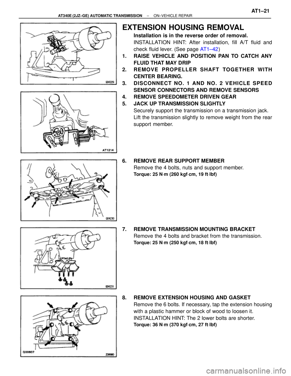
EXTENSION HOUSING REMOVAL
Installation is in the reverse order of removal.
INSTALLATION HINT: After installation, fill A/T fluid and
check fluid lever. (See page AT1±42)
1. RAISE VEHICLE AND POSITION PAN TO CATCH ANY
FLUID THAT MAY DRIP
2. REMOVE PROPELLER SHAFT TOGETHER WITH
CENTER BEARING.
3. DISCONNECT NO. 1 AND NO. 2 VEHICLE SPEED
SENSOR CONNECTORS AND REMOVE SENSORS
4. REMOVE SPEEDOMETER DRIVEN GEAR
5. JACK UP TRANSMISSION SLIGHTLY
Securely support the transmission on a transmission jack.
Lift the transmission slightly to remove weight from the rear
support member.
6. REMOVE REAR SUPPORT MEMBER
Remove the 4 bolts, nuts and support member.
Torque: 25 NVm (260 kgfVcm, 19 ftVlbf)
7. REMOVE TRANSMISSION MOUNTING BRACKET
Remove the 4 bolts and bracket from the transmission.
Torque: 25 NVm (250 kgfVcm, 18 ftVlbf)
8. REMOVE EXTENSION HOUSING AND GASKET
Remove the 6 bolts. If necessary, tap the extension housing
with a plastic hammer or block of wood to loosen it.
INSTALLATION HINT: The 2 lower bolts are shorter.
Torque: 36 NVm (370 kgfVcm, 27 ftVlbf)
± AT340E (2JZ±GE) AUTOMATIC TRANSMISSIONON±VEHICLE REPAIRAT1±21
Page 415 of 2543
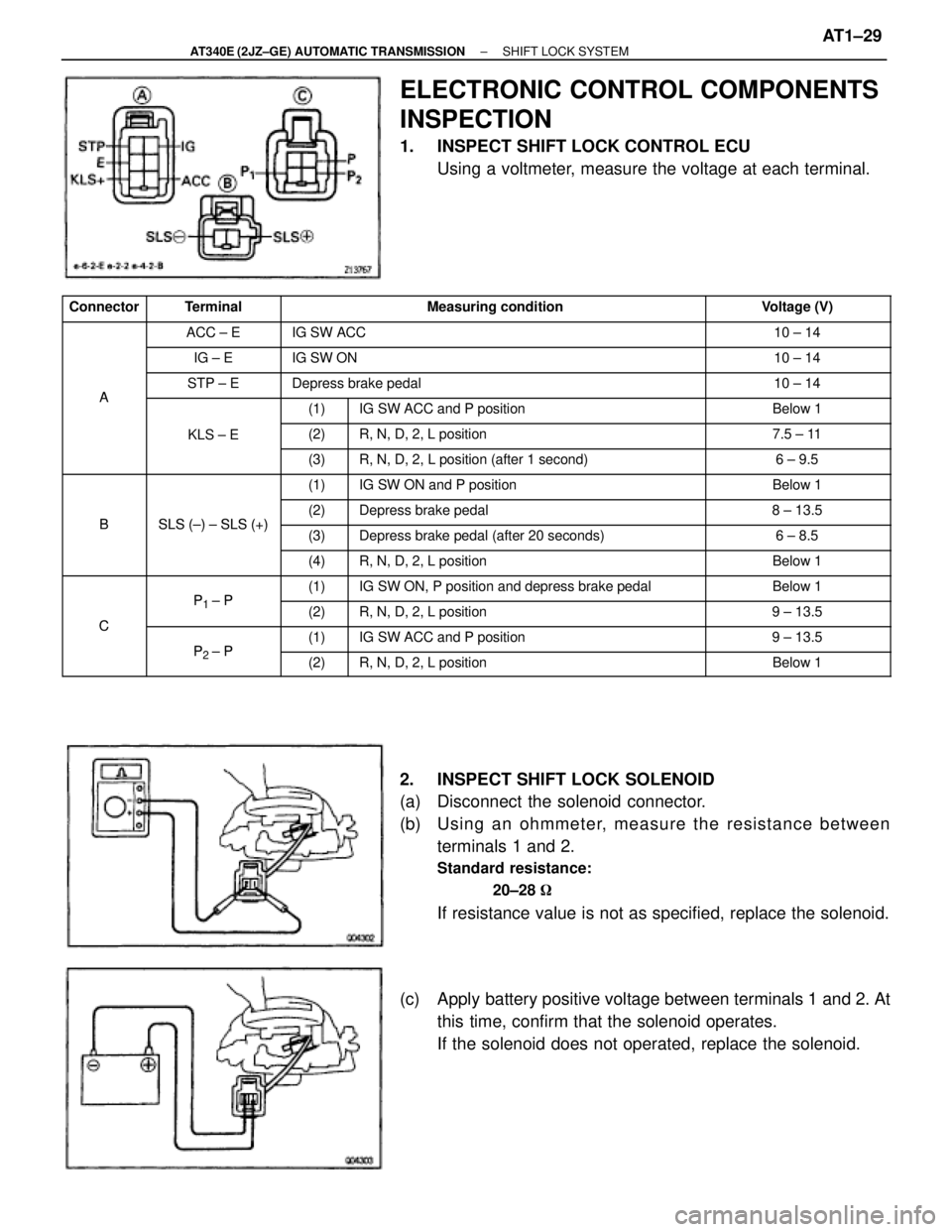
ELECTRONIC CONTROL COMPONENTS
INSPECTION
1. INSPECT SHIFT LOCK CONTROL ECU
Using a voltmeter, measure the voltage at each terminal.
����� �����Connector������ ������Terminal������������������� �������������������Measuring condition��������� ���������Voltage (V)
����� ����������� ������ACC ± E������������������� �������������������IG SW ACC��������� ���������10 ± 14
����� ����������� ������IG ± E������������������� �������������������IG SW ON��������� ���������10 ± 14
����� �����
A
������ ������STP ± E������������������� �������������������Depress brake pedal��������� ���������10 ± 14
����� �����A������ ���������� ����(1)���������������� ����������������IG SW ACC and P position��������� ���������Below 1
����� ����������� ������KLS ± E���� ����(2)���������������� ����������������R, N, D, 2, L position��������� ���������7.5 ± 11����� ����������� ���������� ����(3)���������������� ����������������R, N, D, 2, L position (after 1 second)��������� ���������6 ± 9.5����� ����������� ���������� ����(1)���������������� ����������������IG SW ON and P position��������� ���������Below 1����� �����
B
������ ������
SLS ( ) SLS (+)
���� ����(2)���������������� ����������������Depress brake pedal��������� ���������8 ± 13.5����� �
���� �����
B������ �
����� ������
SLS (±) ± SLS (+)���� �
��� ����(3)���������������� �
��������������� ����������������Depress brake pedal (after 20 seconds)��������� �
�������� ���������6 ± 8.5
����� ����������� ���������� ����(4)���������������� ����������������R, N, D, 2, L position��������� ���������Below 1
����� ����������� ������P1P���� ����(1)���������������� ����������������IG SW ON, P position and depress brake pedal��������� ���������Below 1
����� �����C������ ������
P1 ± P
���� ����(2)���������������� ����������������R, N, D, 2, L position��������� ���������9 ± 13.5
����� �����C������ ������P2P���� ����(1)���������������� ����������������IG SW ACC and P position��������� ���������9 ± 13.5
����� ����������� ������P2 ± P���� ����(2)���������������� ����������������R, N, D, 2, L position��������� ���������Below 1
2. INSPECT SHIFT LOCK SOLENOID
(a) Disconnect the solenoid connector.
(b) Usin g an oh mme te r, me a su re th e re sista n ce be twe e n
terminals 1 and 2.
Standard resistance:
20±28 �
If resistance value is not as specified, replace the solenoid.
(c) Apply battery positive voltage between terminals 1 and 2. At
this time, confirm that the solenoid operates.
If the solenoid does not operated, replace the solenoid.
± AT340E (2JZ±GE) AUTOMATIC TRANSMISSIONSHIFT LOCK SYSTEMAT1±29
Page 428 of 2543
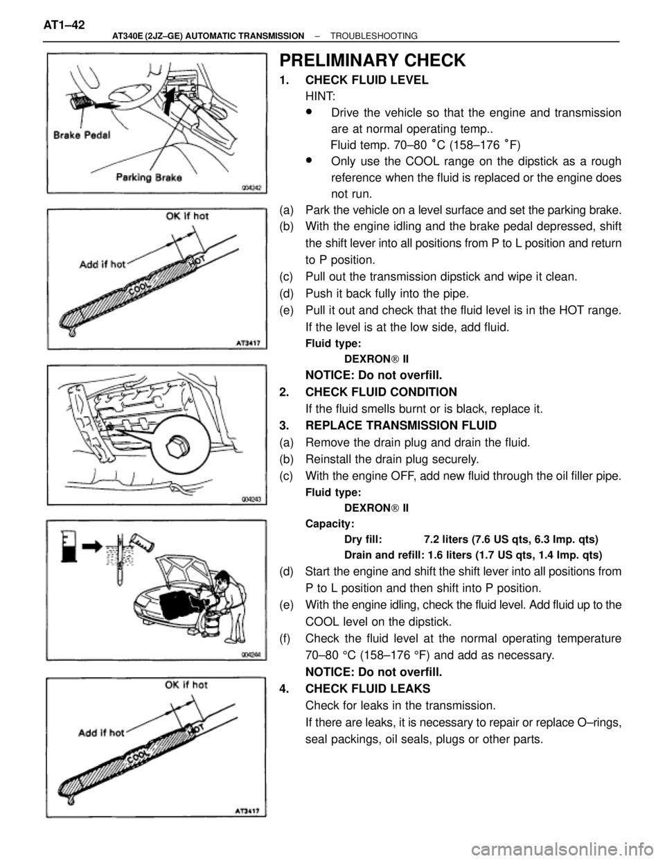
PRELIMINARY CHECK
1. CHECK FLUID LEVEL
HINT:
wDrive the vehicle so that the engine and transmission
are at normal operating temp..
Fluid temp. 70±80 °C (158±176 °F)
wOnly use the COOL range on the dipstick as a rough
reference when the fluid is replaced or the engine does
not run.
(a) Park the vehicle on a level surface and set the parking brake.
(b) With the engine idling and the brake pedal depressed, shift
the shift lever into all positions from P to L position and return
to P position.
(c) Pull out the transmission dipstick and wipe it clean.
(d) Push it back fully into the pipe.
(e) Pull it out and check that the fluid level is in the HOT range.
If the level is at the low side, add fluid.
Fluid type:
DEXRON[ II
NOTICE: Do not overfill.
2. CHECK FLUID CONDITION
If the fluid smells burnt or is black, replace it.
3. REPLACE TRANSMISSION FLUID
(a) Remove the drain plug and drain the fluid.
(b) Reinstall the drain plug securely.
(c) With the engine OFF, add new fluid through the oil filler pipe.
Fluid type:
DEXRON[ II
Capacity:
Dry fill: 7.2 liters (7.6 US qts, 6.3 Imp. qts)
Drain and refill: 1.6 liters (1.7 US qts, 1.4 Imp. qts)
(d) Start the engine and shift the shift lever into all positions from
P to L position and then shift into P position.
(e) With the engine idling, check the fluid level. Add fluid up to the
COOL level on the dipstick.
(f) Check the fluid level at the normal operating temperature
70±80 5C (158±176 5F) and add as necessary.
NOTICE: Do not overfill.
4. CHECK FLUID LEAKS
Check for leaks in the transmission.
If there are leaks, it is necessary to repair or replace O±rings,
seal packings, oil seals, plugs or other parts. AT1±42
± AT340E (2JZ±GE) AUTOMATIC TRANSMISSIONTROUBLESHOOTING
Page 453 of 2543
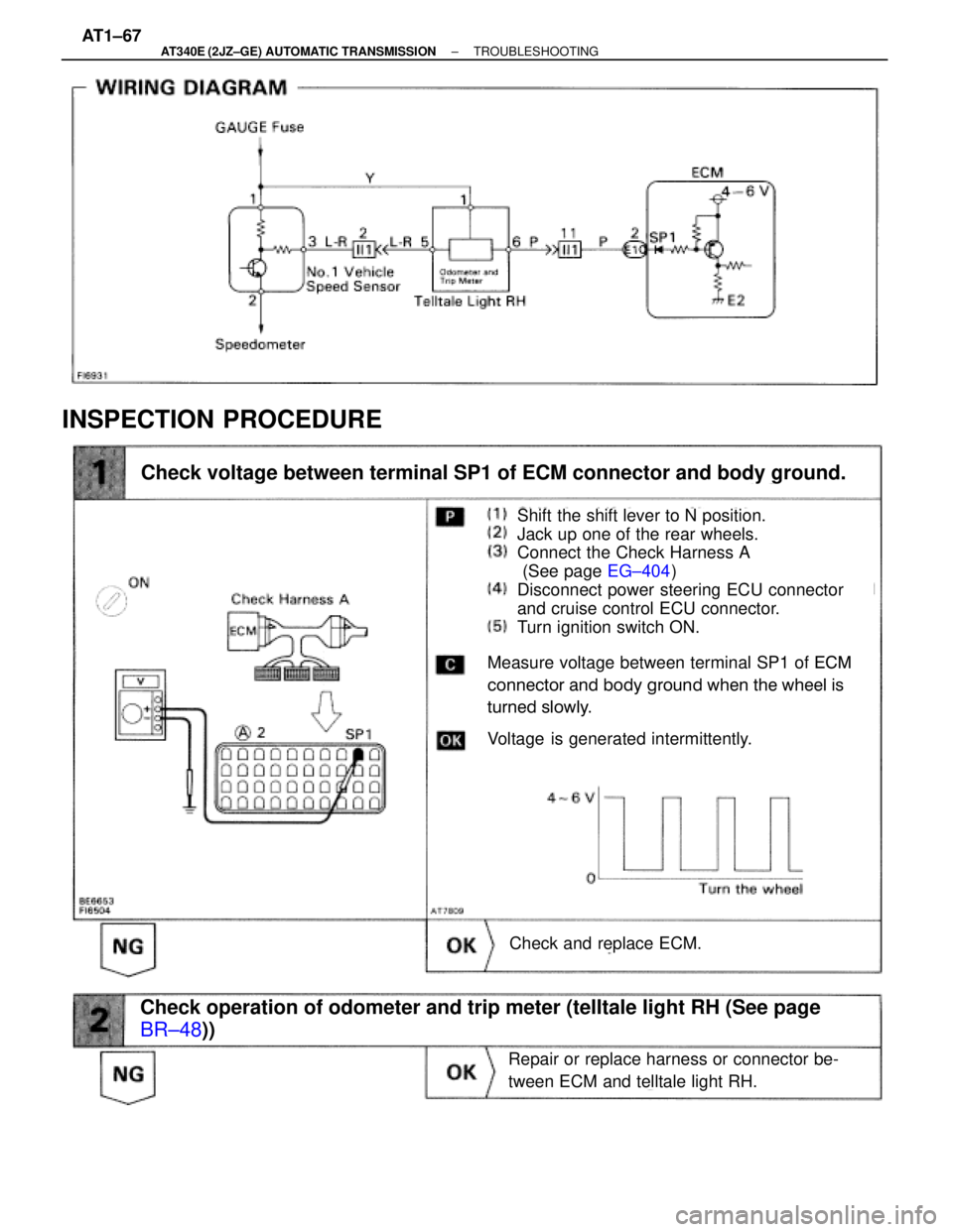
INSPECTION PROCEDURE
Shift the shift lever to N position.
Jack up one of the rear wheels.
Connect the Check Harness A
(See page EG±404)
Disconnect power steering ECU connector
and cruise control ECU connector.
Turn ignition switch ON.
Measure voltage between terminal SP1 of ECM
connector and body ground when the wheel is
turned slowly.
Check voltage between terminal SP1 of ECM connector and body ground.
Voltage is generated intermittently.
Check and replace ECM.
Repair or replace harness or connector be-
tween ECM and telltale light RH.
Check operation of odometer and trip meter (telltale light RH (See page
BR±48))
AT1±67± AT340E (2JZ±GE) AUTOMATIC TRANSMISSIONTROUBLESHOOTING
Page 477 of 2543
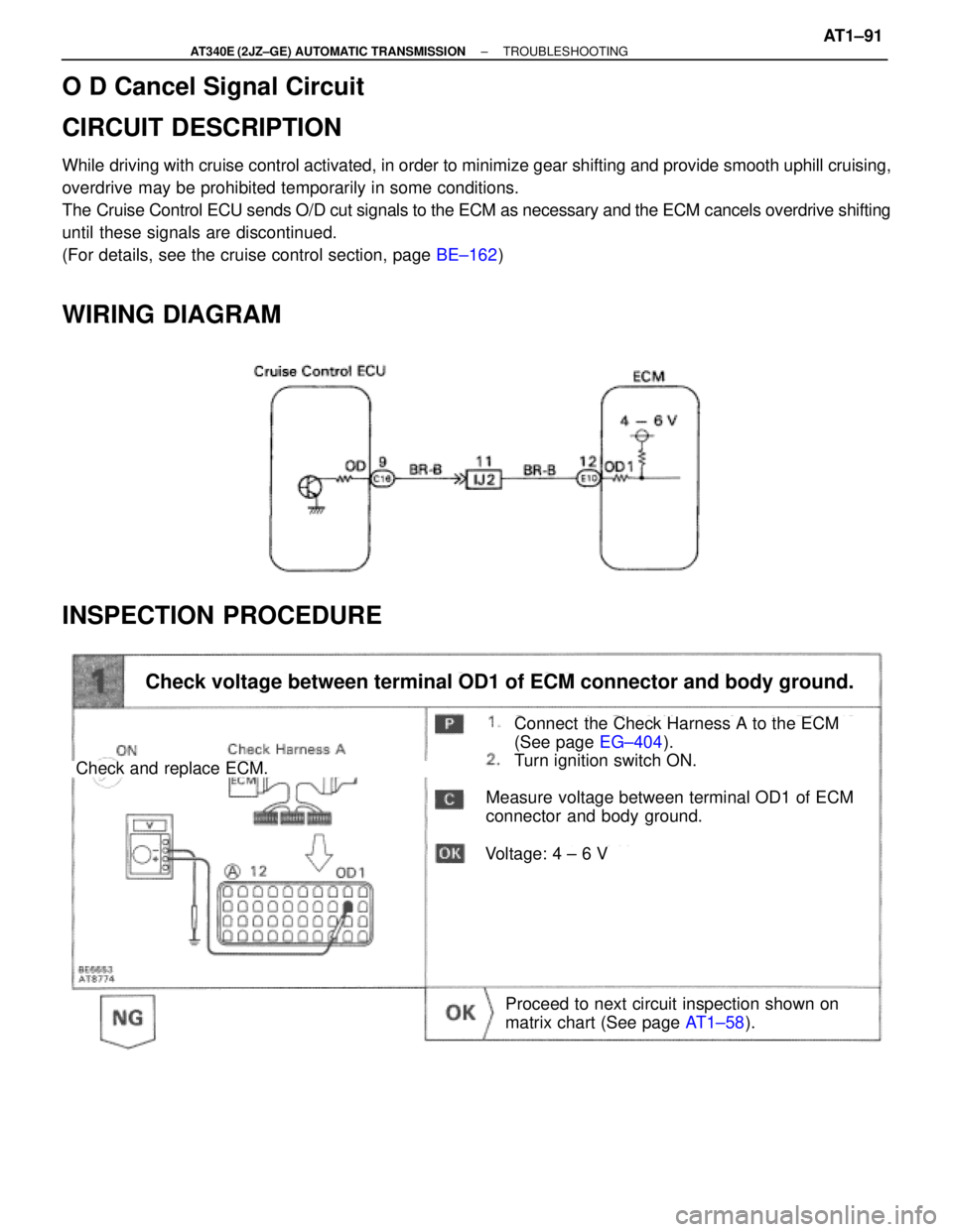
O D Cancel Signal Circuit
CIRCUIT DESCRIPTION
While driving with cruise control activated, in order to minimize gear shifting and provide smooth uphill cruising,
overdrive may be prohibited temporarily in some conditions.
The Cruise Control ECU sends O/D cut signals to the ECM as necessary and the ECM cancels overdrive shifting
until these signals are discontinued.
(For details, see the cruise control section, page BE±162)
WIRING DIAGRAM
INSPECTION PROCEDURE
Connect the Check Harness A to the ECM
(See page EG±404).
Turn ignition switch ON.
Check and replace ECM.
Check voltage between terminal OD1 of ECM connector and body ground.
Measure voltage between terminal OD1 of ECM
connector and body ground.
Proceed to next circuit inspection shown on
matrix chart (See page AT1±58).
Voltage: 4 ± 6 V
± AT340E (2JZ±GE) AUTOMATIC TRANSMISSIONTROUBLESHOOTINGAT1±91
Page 478 of 2543
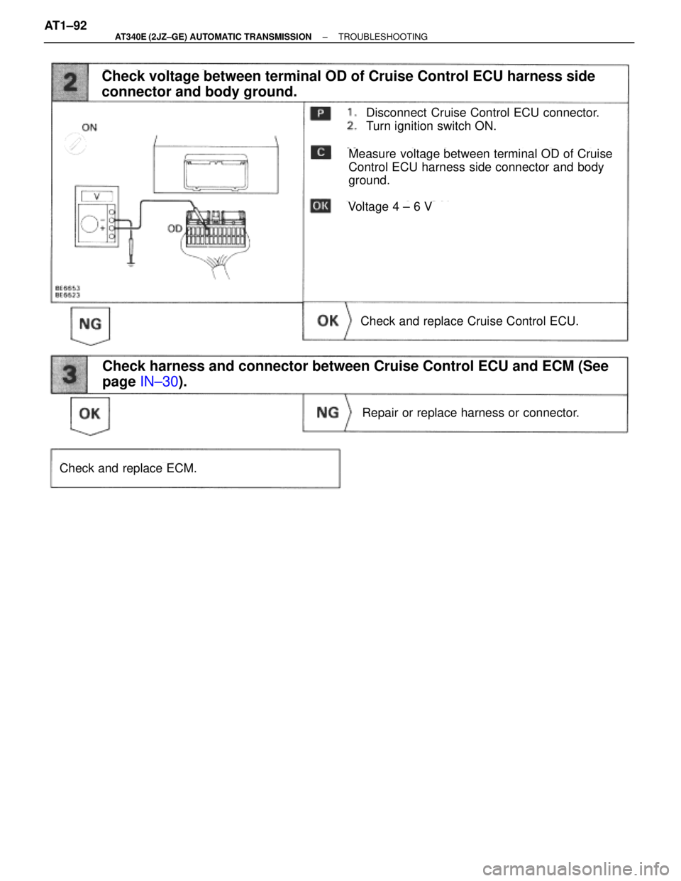
Disconnect Cruise Control ECU connector.
Turn ignition switch ON.
Repair or replace harness or connector.
Check and replace ECM.
Check voltage between terminal OD of Cruise Control ECU harness side
connector and body ground.
Measure voltage between terminal OD of Cruise
Control ECU harness side connector and body
ground.
Voltage 4 ± 6 V
Check and replace Cruise Control ECU.
Check harness and connector between Cruise Control ECU and ECM (See
page IN±30).
AT1±92± AT340E (2JZ±GE) AUTOMATIC TRANSMISSIONTROUBLESHOOTING
Page 491 of 2543
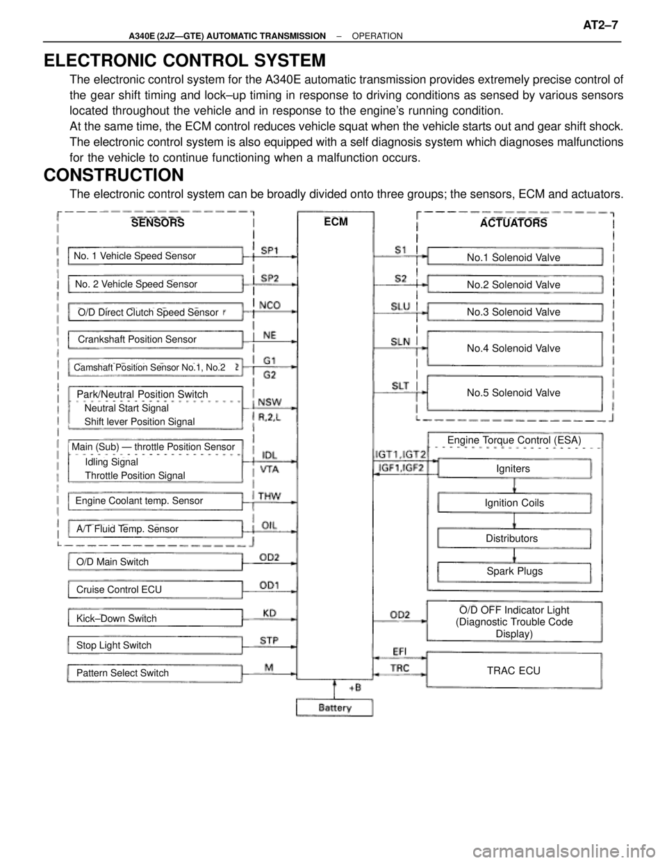
ELECTRONIC CONTROL SYSTEM
The electronic control system for the A340E automatic transmission provides extremely precise control of
the gear shift timing and lock±up timing in response to driving conditions as sensed by various sensors
located throughout the vehicle and in response to the engine's running condition.
At the same time, the ECM control reduces vehicle squat when the vehicle starts out and gear shift shock.
The electronic control system is also equipped with a self diagnosis system which diagnoses malfunctions
for the vehicle to continue functioning when a malfunction occurs.
CONSTRUCTION
The electronic control system can be broadly divided onto three groups; the sensors, ECM and actuators.
No. 1 Vehicle Speed Sensor
No. 2 Vehicle Speed Sensor
Crankshaft Position Sensor
Camshaft Position Sensor No.1, No.2
Park/Neutral Position Switch
� Neutral Start Signal
� Shift lever Position Signal
� Idling Signal
� Throttle Position Signal
Main (Sub) Ð throttle Position Sensor
Engine Coolant temp. Sensor
A/T Fluid Temp. Sensor
O/D Main Switch
Cruise Control ECU
Kick±Down Switch
Stop Light Switch
Pattern Select Switch
SENSORSECMACTUATORS
No.1 Solenoid Valve
No.2 Solenoid Valve
No.3 Solenoid Valve
No.4 Solenoid Valve
No.5 Solenoid Valve
Engine Torque Control (ESA)
Igniters
Ignition Coils
Distributors
Spark Plugs
O/D OFF Indicator Light
(Diagnostic Trouble Code
Display)
TRAC ECU
O/D Direct Clutch Speed Sensor
± A340E (2JZÐGTE) AUTOMATIC TRANSMISSIONOPERATIONAT2±7