Page 1743 of 2543

CIRCUIT DESCRIPTION
The squib circuit consists of the center airbag sensor assembly, spiral cable, steering wheel pad and front pas-
senger airbag assembly. It ca")
DTC 12 Short in Squib Circuit (to B+)
CIRCUIT DESCRIPTION
The squib circuit consists of the center airbag sensor assembly, spiral cable, steering wheel pad and front pas-
senger airbag assembly. It causes the SRS to deploy when the SRS deployment conditions are satisfied.
The front airbag sensor detects the deceleration force in a frontal collision and is located in the front fender on
the left and right sides.
For details of the function of each component, see FUNCTION OF COMPONENTS on page RS±4.
Diagnostic trouble code 12 is recorded when a B+ short is detected in the squib circuit or the front airbag sensor
circuit.
������ ������DTC No.������������������������������� �������������������������������Diagnosis������ �
����� �
����� �
����� �
����� �
����� ������
12
������������������������������� �
������������������������������ �
������������������������������ �
������������������������������ �
������������������������������ �
������������������������������ �������������������������������
� Short circuit in squib wire harness (to B +).
� Squib malfunction.
� Short circuit in front airbag sensor + S wire harness (to B +).
� Front airbag sensors malfunction.
� Spiral cable malfunction.
� Center airbag sensor assembly malfunction.
RS±60± SUPPLEMENTAL RESTRAINT SYSTEMTROUBLESHOOTING
Page 1744 of 2543

Preparation.
Disconnect center airbag sensor assembly connec-
tor.
Measure resistance between terminals +SR and
±SR, +SL and ±SL of harness side connector of
center airbag sensor assembly.
Resistance: 755 � Ð 855 �
Repair or replace harness or connector between
center airbag sensor assembly and front airbag
sensor (See page RS±36).
Check front airbag sensor circuit. (Measure resistance between terminals
+SR and ±SR, +SL and ±SL of center airbag sensor assembly connector.)
Check front airbag sensor circuit. (Measure resistance between terminals
+SR or +SL of center airbag sensor assembly connector and body ground.)
(1) Disconnect negative (±) terminal cable from the
battery, and wait at least 90 seconds.
(2) Remove steering wheel pad (See page RS±10).
(3) Disconnect connector of front passenger airbag
assembly (See page RS±20).
Store the steering wheel pad with the front surface
facing upward.
Go to code 15.
(1) Connect negative (±) terminal cable to battery.
(2) Turn ignition switch ON.
Measure voltage between terminals +SR or +SL of
harness side connector of center airbag sensor as-
sembly and body ground.
Voltage: 0 Ð 0.1 V
INSPECTION PROCEDURES [P] Preparation [C] Check
± SUPPLEMENTAL RESTRAINT SYSTEMTROUBLESHOOTINGRS±61
Page 1745 of 2543
Check D squib circuit.
For the connector for the center airbag sensor as-
sembly side) between center airbag sensor assem-
bly and front passenger airbag assembly, measure
the voltage between P
+ and body ground.
Voltage: 0 V
Check P squib circuit.
Disconnect center airbag sensor assembly connec-
tor.
For the connector (on the spiral cable side) between
the spiral cable and steering wheel pad, measure
the voltage between D
+ and body ground.
Voltage: 0 V
Repair or replace harness or connector between
the center airbag sensor assembly and front pas-
senger airbag sensor assembly.
RS±62± SUPPLEMENTAL RESTRAINT SYSTEMTROUBLESHOOTING
Page 1747 of 2543
 Turn ignition switch to LOCK.
(2) Disconnect negative (±) terminal cable from the
battery, and wait at least 90 seconds.
(3) Connect steering wheel pad connector.
(4) Connect negat")
Check D squib.
(1) Turn ignition switch to LOCK.
(2) Disconnect negative (±) terminal cable from the
battery, and wait at least 90 seconds.
(3) Connect steering wheel pad connector.
(4) Connect negative (±) terminal cable to battery,
and wait at least 2 seconds.
(1) Turn ignition switch to ACC or ON and wait at
least 20 seconds.
(2) Clear malfunction code stored in memory.
(See page RS±47)
(3) Turn ignition switch to LOCK, and wait at least
20 seconds.
(4) Turn ignition switch to ACC or ON, and wait at
least 20 seconds.
(5) Using SST, connect terminals Tc and E
1 of
DLC1 or DLC2.
SST 09843±18020
(6) Check diagnostic trouble code.
Diagnostic trouble code 12 is not output.
Codes other than code 12 may be output at this
time, but they are not relevant to this check.
Check D squib.
(1) Turn ignition switch to LOCK.
(2) Disconnect negative (±) terminal cable from the
battery, and wait at least 90 seconds.
(3) Connect front passenger airbag assembly con±
nectar.
(4) Connect negative (±) terminal cable to battery,
and wait at least 2 seconds.
(1) Turn ignition switch to ACC or ON and wait at
least 20 seconds.
(2) Clear malfunction code stored in memory.
(See page RS±47)
(3) Turn ignition switch to LOCK, and wait at least
20 seconds.
(4) Turn ignition switch to ACC or ON, and wait at
least 20 seconds.
(5) Using SST, connect terminals Tc and E
1 of
DLC1 or DLC2.
SST 09843±18020
(6) Check diagnostic trouble code.
Diagnostic trouble code 12 is not output.
Codes other than code 12 may be output at this
time, but they are not relevant to this check.
Replace steering wheel pad.
Replace front passenger airbag assembly. RS±64
± SUPPLEMENTAL RESTRAINT SYSTEMTROUBLESHOOTING
Page 1748 of 2543
������������������������������������ �
����������������������������������� ������������������������������������
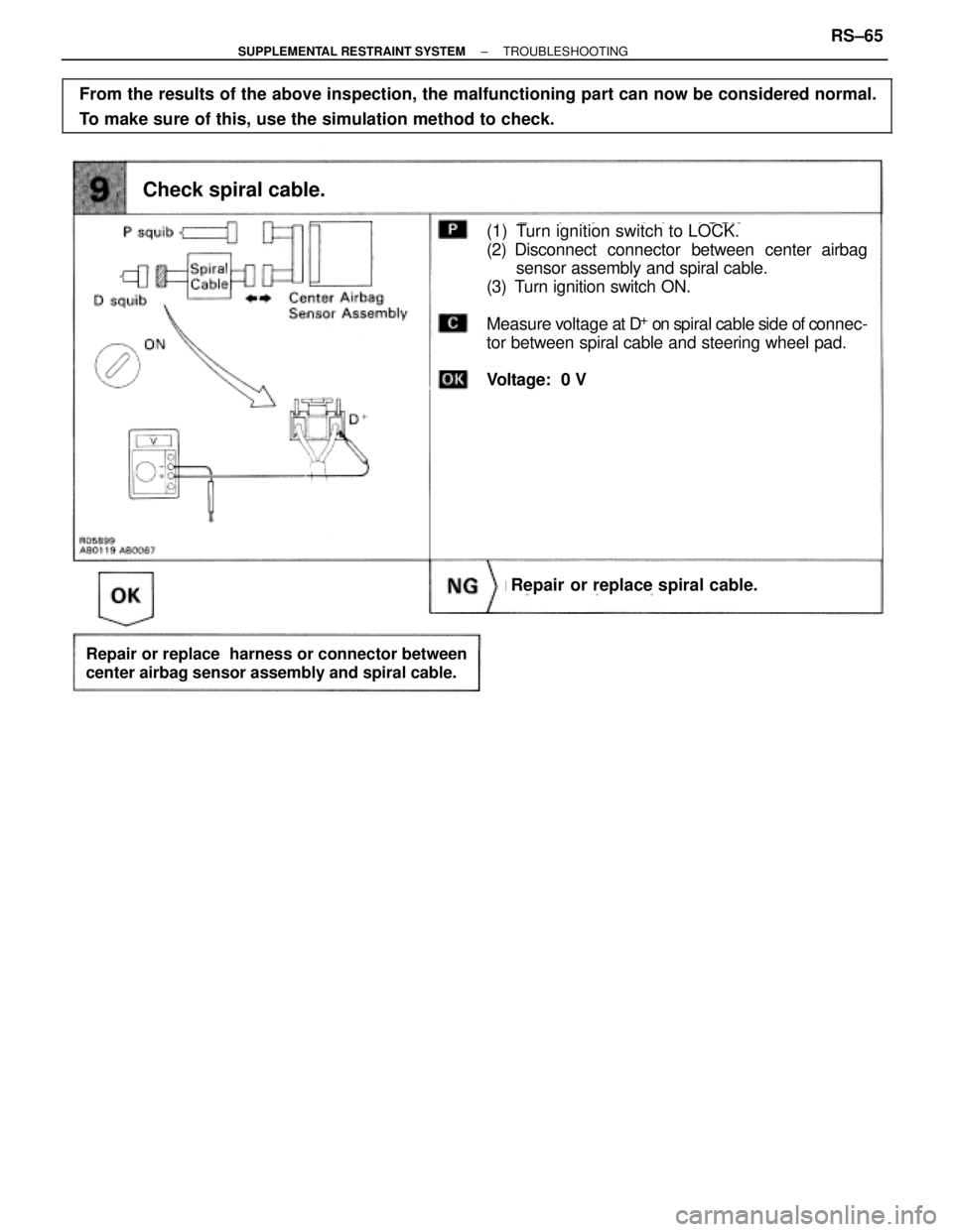
From the results of the above inspection, the malfunctioning part can now be considered normal.
To make sure of this, use the simulation method to check.
Check spiral cable.
Repair or replace spiral cable.
Repair or replace harness or connector between
center airbag sensor assembly and spiral cable.
(1) Turn ignition switch to LOCK.
(2) Disconnect connector between center airbag
sensor assembly and spiral cable.
(3) Turn ignition switch ON.
Measure voltage at D
+ on spiral cable side of connec-
tor between spiral cable and steering wheel pad.
Voltage: 0 V
± SUPPLEMENTAL RESTRAINT SYSTEMTROUBLESHOOTINGRS±65
Page 1749 of 2543

CIRCUIT DESCRIPTION
The D squib circuit consists of the center airbag sensor assembly, spiral cable and steering wheel p")
DTC 13 Short in D Squib Circuit (Between D+
Wire Harness and D±
Wire Harness)
CIRCUIT DESCRIPTION
The D squib circuit consists of the center airbag sensor assembly, spiral cable and steering wheel pad.
It causes the airbag to deploy when the airbag deployment conditions are satisfied.
For details of the function of each component, see FUNCTION OF COMPONENTS on page RS±4.
Diagnostic trouble code 13 is recorded when a short is detected in the D
+ wire harness and D± wire harness
of the squib circuit.
����� �
���� �����DTC No.
�������������������������������� �
������������������������������� ��������������������������������Diagnosis
����� �
���� �
���� �
���� �����
13
�������������������������������� �
������������������������������� �
������������������������������� �
������������������������������� ��������������������������������
� Short circuit between D+ wire harness and D± wire harness of squib.
� D squib malfunction.
� Spiral cable malfunction.
� Center airbag sensor assembly malfunction.
RS±66± SUPPLEMENTAL RESTRAINT SYSTEMTROUBLESHOOTING
Page 1750 of 2543
INSPECTION PROCEDURES [P] Preparation [C] Check
Preparation.
(1) Disconnect negative (±) terminal cable from the
battery, and wait at least 90 seconds.
(2) Remove steering wheel pad (See page RS±10).
(3) Disconnect connector of front passenger airbag
assembly (See page RS±20).
Check D squib circuit.
For the connector (on the spiral cable side) be-
tween the spiral cable and steering wheel pad,
measure the resistance between D
+ and D±.
Resistance: 1 k� or higher.
Store the steering wheel pad with the front surface
facing upward.
± SUPPLEMENTAL RESTRAINT SYSTEMTROUBLESHOOTINGRS±67
Page 1751 of 2543
 Turn ignition switch to ACC or ON and wait at
least 20 seconds.
(2) Clear malfunction code stored in memory. (See
page RS±47)
(3) Turn ignition switch to LOCK")
Check center airbag sensor assembly.
(1) Turn ignition switch to ACC or ON and wait at
least 20 seconds.
(2) Clear malfunction code stored in memory. (See
page RS±47)
(3) Turn ignition switch to LOCK, and wait at least
20 seconds.
(4) Remove the service wire which connects D
+ and
D± on spiral cable side of connector between
spiral cable and steering wheel pad.
(5) Turn ignition switch to ACC or ON, and wait at
least 20 seconds.
(6) Using SST, connect terminals Tc and E
1 of DLC1
or DLC2.
SST 09843±18020
(7) Check diagnostic trouble code.
Diagnostic trouble code 13 is not output.
Codes other than code 13 may be output at this
time, but they are not relevant to this check.
Replace center airbag sensor assembly.
(1) Using a service wire, connect D+ and D± on spiral
cable side of connector between spiral cable and
steering wheel pad.
(2) Using a service wire, connect P+ and P± on cen±
ter airbag sensor assembly side of connector
between center airbag sensor assembly and
front passenger airbag assembly.
(3) Connect negative (±) terminal cable to battery, and
wait at least 2 seconds. RS±68
± SUPPLEMENTAL RESTRAINT SYSTEMTROUBLESHOOTING
 between center airbag sensor assem-
bly and front passenger airbag assembly, measure
the voltage between P
+ and")
![TOYOTA SUPRA 1995 Service Repair Manual INSPECTION PROCEDURES [P] Preparation [C] Check
Preparation.
(1) Disconnect negative (±) terminal cable from the
battery, and wait at least 90 seconds.
(2) Remov](/manual-img/14/57468/w960_57468-1749.png "TOYOTA SUPRA 1995 Service Repair Manual INSPECTION PROCEDURES [P] Preparation [C] Check
Preparation.
(1) Disconnect negative (±) terminal cable from the
battery, and wait at least 90 seconds.
(2) Remov")