Page 733 of 2543
INSPECTION PROCEDURE
HINT: This troubleshooting is based on the premise that engine cranking occurs.
If the engine does not crank, proceed to engine troubleshooting on page EG±381 or 487 (Vol. 1).
(See page IN±30).
(1)Remove instrument panel panel.
(See BO section.)
(2)Disconnect the ECU connector.
Measure voltage between terminal SRLY of theft
deterrent ECU connector and body ground when
ignition switch is turned on.
Voltage: 10 ± 14 V
Check and replace theft deterrent ECU.
Check voltage between terminal SRLY of theft deterrent and door lock
ECU connector and body ground.
Check and repair harness and connector between starter and theft deterrent and door lock ECU
± BODY ELECTRICAL SYSTEMTHEFT DETERRENT AND DOOR LOCK CONTROL SYSTEMBE±131
Page 750 of 2543
Engine Hood Courtesy Switch Circuit
CIRCUIT DESCRIPTION
The engine hood courtesy switch is built into the engine hood lock assembly and goes on when the engine hood
is opened and goes off when the engine hood is closed.
BE±148± BODY ELECTRICAL SYSTEM
THEFT DETERRENT AND DOOR LOCK CONTROL SYSTEM
Page 751 of 2543
INSPECTION PROCEDURE
(See page IN±30).
(1) Remove engine hood lock assembly.
(2) Disconnect engine hood courtesy switch con-
nector.
Check continuity between terminals 1 and 2 when
engine hood lock is locked and unlocked.
Check and replace theft deterrent and door lock
ECU (See page
IN±30).
Check engine hood courtesy switch.
Engine hood lock
Lock
Unlock
Terminal
Continuity
12
Repair or replace harness or connector.
Replace engine hood courtesy switch.
Check harness and connector between theft deterrent and door lock ECU
and switch and body ground (See page IN±30).
± BODY ELECTRICAL SYSTEMBE±149THEFT DETERRENT AND DOOR LOCK CONTROL SYSTEM
Page 771 of 2543

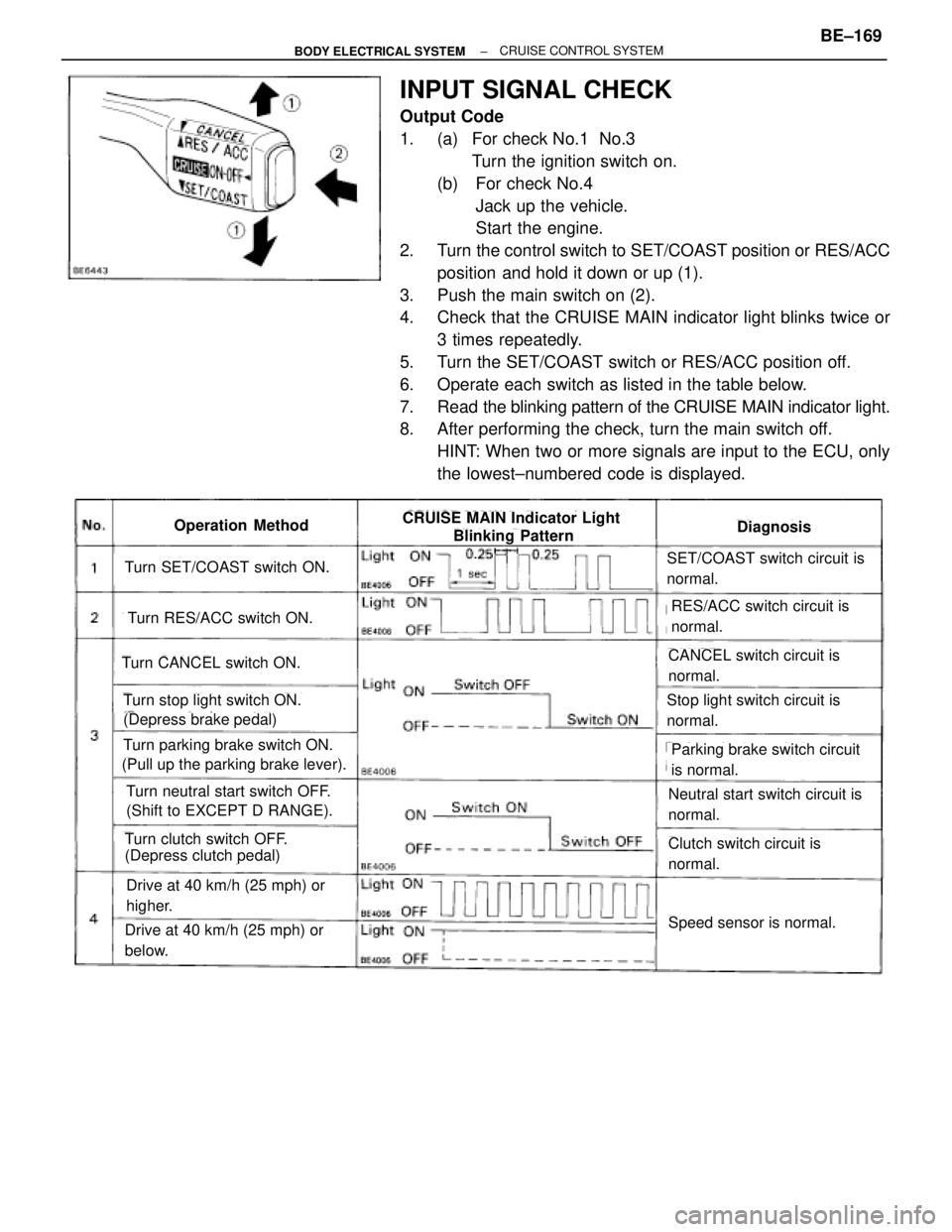
INPUT SIGNAL CHECK
Output Code
1. (a) For check No.1 No.3
Turn the ignition switch on.
(b) For check No.4
Jack up the vehicle.
Start the engine.
2. Turn the control switch to SET/COAST position or RES/ACC
position and hold it down or up (1).
3. Push the main switch on (2).
4. Check that the CRUISE MAIN indicator light blinks twice or
3 times repeatedly.
5. Turn the SET/COAST switch or RES/ACC position off.
6. Operate each switch as listed in the table below.
7. Read the blinking pattern of the CRUISE MAIN indicator light.
8. After performing the check, turn the main switch off.
HINT: When two or more signals are input to the ECU, only
the lowest±numbered code is displayed.
Turn SET/COAST switch ON.
Turn RES/ACC switch ON.
Turn CANCEL switch ON.
Turn stop light switch ON.
(Depress brake pedal)
Turn parking brake switch ON.
(Pull up the parking brake lever).
Turn neutral start switch OFF.
(Shift to EXCEPT D RANGE).
Turn clutch switch OFF.
(Depress clutch pedal)
Drive at 40 km/h (25 mph) or
higher.
Drive at 40 km/h (25 mph) or
below.
SET/COAST switch circuit is
normal.
RES/ACC switch circuit is
normal.
CANCEL switch circuit is
normal.
Stop light switch circuit is
normal.
Parking brake switch circuit
is normal.
Neutral start switch circuit is
normal.
Clutch switch circuit is
normal.
Speed sensor is normal.
DiagnosisOperation MethodCRUISE MAIN Indicator Light
Blinking Pattern
± BODY ELECTRICAL SYSTEMBE±169CRUISE CONTROL SYSTEM
Page 786 of 2543
Idle Switch Circuit
CIRCUIT DESCRIPTION
When the idle switch is turned ON, a signal is sent to the ECU. The ECU uses this signal to correct the discrepan-
cy between the throttle valve position and the actuator position sensor value to enable accurate cruise control
at the set speed. If the idle switch is malfunctioning, problem symptoms also occur in the engine, so also inspect
the engine.
WIRING DIAGRAM
BE±184± BODY ELECTRICAL SYSTEMCRUISE CONTROL SYSTEM
Page 789 of 2543
INSPECTION PROCEDURE
(1) Disconnect ECU connector.
(2) Turn ignition switch ON.
(3) Measure voltage between terminal OD of har±
ness side connector of ECU and body ground.
Check voltage between terminal OD of harness side connector ECU and
body ground.
Check operation of overdrive.
Remove ECU with connector still connected.
Check and Repair Electronically controlled transmis-
sion (See AT section).
Voltage: 10 ± 14 V
Go to step
Go to step
Test drive after engine warm up.
Check that overdrive ON e OFF occurs with operation of OD switch ON±OFF.
± BODY ELECTRICAL SYSTEMCRUISE CONTROL SYSTEMBE±187
Page 790 of 2543
(See page IN±30).
Check voltage between terminal ECT of cruise control ECU connector and
body ground (On test drive).
(1) Connect ECU connector.
(2) Test drive after engine warm up.
Proceed to next circuit inspection shown on
matrix chart (See page BE±170).
Check voltage between terminal ECT of
cruise control ECU connector and body
ground when OD switch is on and off.
Repair or replace harness or connector.
Check and replace ECU.
Check and repair ECU.
Repair or replace harness or connector.
Check for open and short in harness and connector between terminal OD1
of ECU and terminal OD1 of ECM (See page IN±30).
Check for open and short in harness and connector between terminal ECT cruise
control ECU and electronically controlled transmission solenoid(See page
IN±30).
VoltageGear Position
BE±188± BODY ELECTRICAL SYSTEMCRUISE CONTROL SYSTEM
Page 792 of 2543

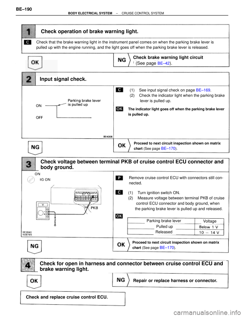
(See page BE±42).
BE±169.
Proceed to next circuit inspection shown on matrix
chart (See page
BE±170).
(1) See input signal check on page BE±169.
(2) Check the indicator light when the parking brake
lever is pulled up.
Check operation of brake warning light.
Check voltage between terminal PKB of cruise control ECU connector and
body ground.
(1) Turn ignition switch ON.
(2) Measure voltage between terminal PKB of cruise
control ECU connector and body ground, when
the parking brake lever is pulled up and released.
Remove cruise control ECU with connectors still con-
nected.
Input signal check.
The indicator light goes off when the parking brake lever
is pulled up.
Check that the brake warning light in the instrument panel comes on when the parking brake lever is
pulled up with the engine running, and the light goes off when the parking brake lever is released.
Check brake warning light circuit
Parking brake lever
Proceed to next circuit inspection shown on matrix
chart (See page
BE±170).
Voltage
Pulled up
Released
Check for open in harness and connector between cruise control ECU and
brake warning light.
Repair or replace harness or connector.
Check and replace cruise control ECU. BE±190
± BODY ELECTRICAL SYSTEMCRUISE CONTROL SYSTEM