Page 983 of 2543
Ts Terminal Circuit
CIRCUIT DESCRIPTION
The sensor check circuit detects abnormalities in the speed sensor signal which cannot be detected with the
diagnostic trouble code check.
Connecting terminals Ts and E1 of the DLC1 in the engine compartment starts the check.
Check for open and short in harness and connector between ABS (&TRAC)
ECU and DLC1, DLC1 and body ground (See page IN±30).
Turn ignition switch ON.
Measure voltage between terminals Ts and E1 of
DLC1.
Voltage: 10 ± 14 V
If ABS warning light does not blink even
after Ts and E1 are connected, the ECU may
be defective.
Repair or replace harness or connector.
Check and replace ABS (& TRAC) ECU.
INSPECTION PROCEDURE.
BR±114± BRAKE SYSTEMANTI±LOCK BRAKE SYSTEM (ABS)
Page 997 of 2543

BR±134
BR±137
BR±137
BR±138
BR±138
BR±138
BR±138
BR±142
BR±145
BR±147
BR±149
BR±149
BR±152
BR±152
BR±155
BR±156
BR±157
Open or short in sub±throttle actuator circuit
Step motor does not move to a position decided by ECU
Sub±throttle valve does not move even when the sub±throttle
valve is controlled to fully open position by ECU
Right front wheel speed sensor signal malfunction
Left front wheel speed sensor signal malfunction
Right rear wheel speed sensor signal malfunction
Left rear wheel speed sensor signal malfunction
Low battery positive voltage or abnormally high battery
positive voltage
Malfunction in ABS or TRAC (BRAKE) control system
Open or short in NE signal circuit
Main throttle position sensor circuit malfunction
Open or short in main throttle position sensor circuit
Sub±throttle position sensor circuit malfunction
Open or short in sub±throttle position sensor circuit
Engine & ECT system malfunction
ECM communication circuit malfunction
ABS & TRAC ECU communication circuit malfunction
Malfunction in TRAC ECU
DiagnosisCodeTRAC Indicator Light
Blinking PatternSee page
DIAGNOSTIC TROUBLE CODE CHART
If a malfunction code is displayed during the diagnostic trouble code check, check the circuit listed for that code
in the table below and proceed to the relevant page.
HINT: If the TRAC indicator light lights up and the TRAC indicator light does not blink when the DTC is checked,
check the blinking pattern of the ABS warning light and troubleshoot the ABS system.
*
1: If a malfunction is detected in ABS the TRAC OFF indicator light lights up instead of the TRAC indicator
light.
*
2: The TRAC indicator light does not light up even if an error is detected
*3: If a malfunction is detected, the TRAC OFF indicator light lights up instead of the TRAC indicator light.
*4: Depending on the malfunction, the TRAC indicator light does not light up. BR±128
± BRAKE SYSTEMTRACTION CONTROL SYSTEM (TRAC)
Page 1001 of 2543
Symbols
(Terminals No.)
Always
Always
IG switch ON
5 seconds after IG switch ON
Sub throttle valve fully open
5 seconds after IG switch ON
Sub throttle valve fully op")
TRAC ECU:
ConditionSTD Voltage (V)Symbols
(Terminals No.)
Always
Always
IG switch ON
5 seconds after IG switch ON
Sub throttle valve fully open
5 seconds after IG switch ON
Sub throttle valve fully open
5 seconds after IG switch ON
Sub throttle valve fully open
5 seconds after IG switch ON
Sub throttle valve fully open
5 seconds after IG switch ON
Sub throttle valve fully open
5 seconds after IG switch ON
Sub throttle valve fully open
Engine idling, Main throttle valve fully closed
Engine idling, Main throttle valve fully open
IG switch ON, Sub throttle valve fully closed
IG switch ON, Sub throttle valve fully open
Idling
IG switch ON, TRAC cut switch pushed in
IG switch ON, TRAC cut switch released
IG switch ON, PKB switch ON
Fluid in M/C reservoir above MIN level
IG switch ON, PKB switch OFF
Fluid in M/C reservoir above MIN level
IG switch ON, TRAC indicator light ON
IG switch ON, TRAC OFF indicator light ON
IG switch ON, TRAC OFF indicator light OFF
Stop light switch OFF
Stop light switch ON
IG switch ON
IG switch ON
Slowly turn right front wheel
IG switch ON
Slowly turn left front wheel
IG switch ON
Slowly turn right rear wheel
IG switch ON
Slowly turn left rear wheel
Below 1.0
Below 1.0
Pulse generation
Below 1.5
Below 1.5
Below 2.0
Below 1.5
Pulse generation
Pulse generation
Pulse generation
Pulse generation
BR±132± BRAKE SYSTEMTRACTION CONTROL SYSTEM (TRAC)
Page 1011 of 2543
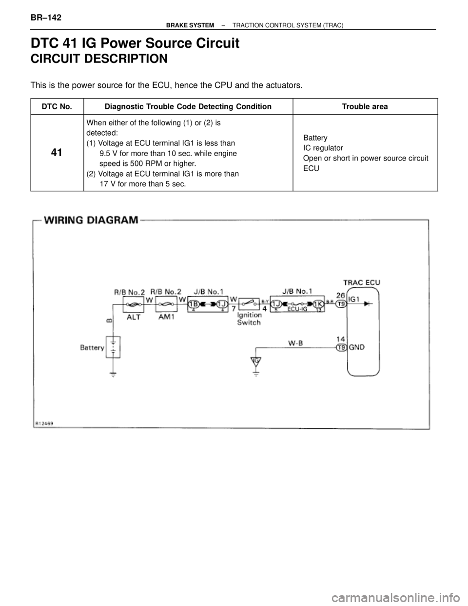
DTC 41 IG Power Source Circuit
CIRCUIT DESCRIPTION
This is the power source for the ECU, hence the CPU and the actuators.
������ ������DTC No.������������������ ������������������Diagnostic Trouble Code Detecting Condition�������������� ��������������Trouble area
������ �
����� �
����� �
����� �
����� �
����� �
����� ������
41
������������������ �
����������������� �
����������������� �
����������������� �
����������������� �
����������������� �
����������������� ������������������
When either of the following (1) or (2) is
detected:
(1) Voltage at ECU terminal IG1 is less than
9.5 V for more than 10 sec. while engine
speed is 500 RPM or higher.
(2) Voltage at ECU terminal IG1 is more than
17 V for more than 5 sec.
�������������� �
������������� �
������������� �
������������� �
������������� �
������������� �
������������� ��������������
� Battery
� IC regulator
� Open or short in power source circuit
� ECU
BR±142± BRAKE SYSTEMTRACTION CONTROL SYSTEM (TRAC)
Page 1016 of 2543
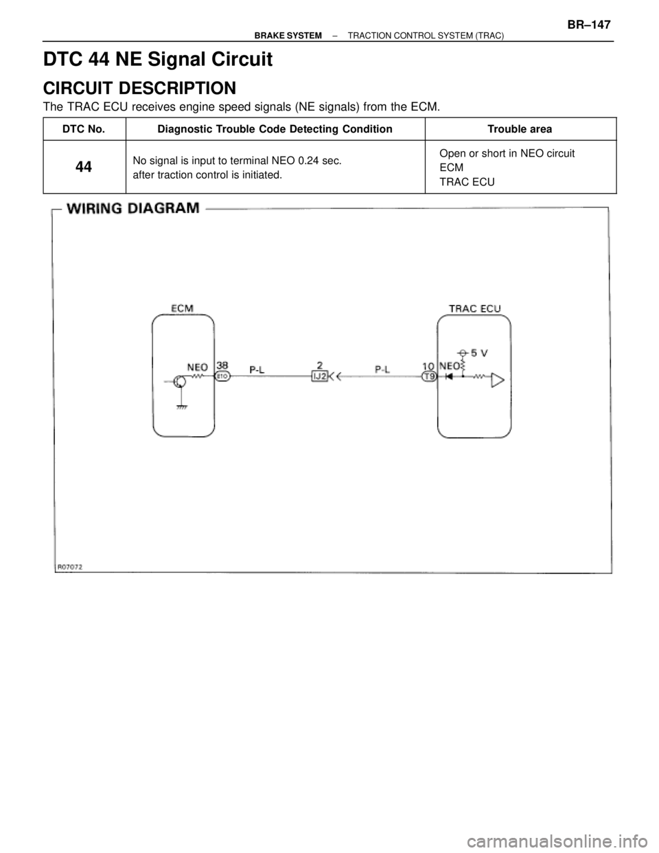
DTC 44 NE Signal Circuit
CIRCUIT DESCRIPTION
The TRAC ECU receives engine speed signals (NE signals) from the ECM.
������ ������DTC No.������������������� �������������������Diagnostic Trouble Code Detecting Condition������������� �������������Trouble area
������ �
����� �
����� ������44
������������������� �
������������������ �
������������������ �������������������
No signal is input to terminal NEO 0.24 sec.
after traction control is initiated.
������������� �
������������ �
������������ �������������
� Open or short in NEO circuit
� ECM
� TRAC ECU
± BRAKE SYSTEMTRACTION CONTROL SYSTEM (TRAC)BR±147
Page 1017 of 2543
(See page IN±30).
Check voltage between terminal NEO of TRAC ECU and body ground.
Remove TRAC ECU with connectors still con-
nected.
Repair or replace harness or connector.
Check and replace TRAC ECU or ECM.
Check for open and short in harness and connector between terminal NEO
of TRAC ECU and terminal NEO of ECM (See page IN±30).
Turn ignition switch ON.
Measure voltage between terminal NEO of TRAC
ECU and body ground for the engine conditions
below
If the same code is still output after the diagnostic code is deleted, check the contact condition of each
connection.
Engine condition
OFF (IG ON)
ON (Idling)
Voltage
4 ± 6 V or Below 1 V
2 ± 3 V (Pulse)
INSPECTION PROCEDURE
BR±148± BRAKE SYSTEMTRACTION CONTROL SYSTEM (TRAC)
Page 1019 of 2543
INSPECTION PROCEDURE
HINT: The main throttle position sensor signal is transmitted to the TRAC ECU from ECM, so if an error occurs
at the engine side, the TRAC ECU also detects it.
If diagnostic trouble code No.41 is being output for the engine troubleshoot the engine first.
Remove TRAC ECU with connectors still con-
nected.
Disconnect the vacuum hose from the throttle
opener, and apply the vacuum to the throttle open-
er.
Is diagnostic trouble code output for the engine?
Turn ignition switch ON.
Measure voltage between terminal IDL1 of TRAC ECU
and body ground, when the main throttle valve is fully clo-
sed and fully open.
Main throttle valve position
Fully closed
Check voltage between terminal IDL1 of TRAC ECU and body ground.
Fully open
Voltage
Below 1.0 V
10 ± 14 V
Do diagnostic trouble code check on page EG±491.
Repair circuit indicated by the code output.
BR±150± BRAKE SYSTEMTRACTION CONTROL SYSTEM (TRAC)
Page 1022 of 2543
INSPECTION PROCEDURE
HINT: The sub±throttle position sensor signal is transmitted to the TRAC ECU from ECM, so if an error occurs
at the engine side, the TRAC ECU also detects it.
If diagnostic trouble code No. 47 is being output for the engine, troubleshoot the engine first.
Check voltage between terminal IDL2 of TRAC ECU and body ground.
Remove TRAC ECU with connectors still con-
nected.
Remove intake air duct.
Disconnect step motor connector.
Repair circuit indicated by the code output.
Do diagnostic trouble code check on page EG±491.
Is diagnostic trouble code output for the engine?
Turn ignition switch ON.
Measure voltage between terminal IDL2 of TRAC ECU
and body ground, when the sub±throttle valve is fully
closed and fully open.
Go to step 6.
Engine condition
Sub±throttle valve position
Fully open
Voltage
Below 1.0 V
10 ± 14 V
Fully closed
± BRAKE SYSTEMTRACTION CONTROL SYSTEM (TRAC)BR±153

.
Check voltage between terminal NEO of TRAC ECU and body ground.
Remove TRAC ECU with connectors still con-
nected.
Repair or replace harness or connector.
Check and replace TRAC ECU")

