Page 1024 of 2543
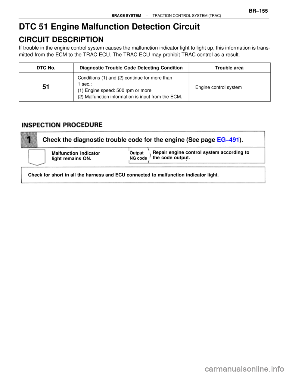
Check the diagnostic trouble code for the engine (See page EG±491).
Check for short in all the harness and ECU connected to malfunction indicator light.
Repair engine control system according to
the code output.Malfunction indicator
light remains ON.Output
NG code
DTC 51 Engine Malfunction Detection Circuit
CIRCUIT DESCRIPTION
If trouble in the engine control system causes the malfunction indicator light to light up, this information is trans-
mitted from the ECM to the TRAC ECU. The TRAC ECU may prohibit TRAC control as a result.
��������� �
��������DTC No.����������������� �
����������������Diagnostic Trouble Code Detecting Condition������������ �
�����������Trouble area��������� �
�������� �
�������� �
�������� �
��������
51
����������������� �
���������������� �
���������������� �
���������������� �
����������������
Conditions (1) and (2) continue for more than
1 sec.:
(1) Engine speed: 500 rpm or more
(2) Malfunction information is input from the ECM.
������������ �
����������� �
����������� �
����������� �
�����������
� Engine control system
± BRAKE SYSTEMTRACTION CONTROL SYSTEM (TRAC)BR±155
Page 1025 of 2543
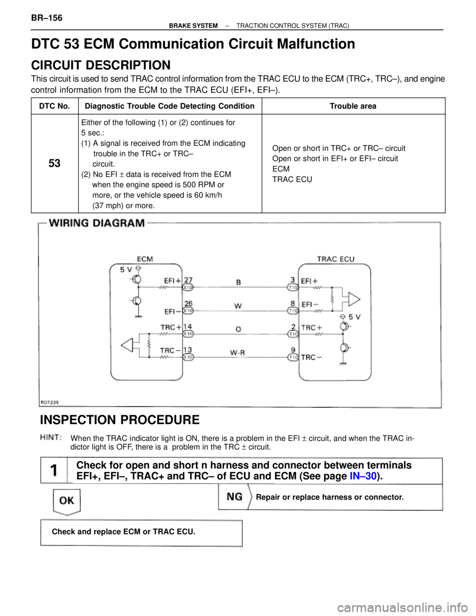
(See page IN±30).
Check for open and short n harness and connector between terminals
EFI+, EFI±, TRAC+ and TRC± of ECU and ECM (See page IN±30).
When the TRAC indicator light is ON, there is a problem in the EFI + circuit, and when the TRAC in-
dictor light is OFF, there is a problem in the TRC + circuit.
Repair or replace harness or connector.
Check and replace ECM or TRAC ECU.
INSPECTION PROCEDURE
DTC 53 ECM Communication Circuit Malfunction
CIRCUIT DESCRIPTION
This circuit is used to send TRAC control information from the TRAC ECU to the ECM (TRC+, TRC±), and engine
control information from the ECM to the TRAC ECU (EFI+, EFI±).
����� �����DTC No.���������������� ����������������Diagnostic Trouble Code Detecting Condition����������������� �����������������Trouble area
����� �
���� �
���� �
���� �
���� �
���� �
���� �
���� �����
53
���������������� �
��������������� �
��������������� �
��������������� �
��������������� �
��������������� �
��������������� �
��������������� ����������������
Either of the following (1) or (2) continues for
5 sec.:
(1) A signal is received from the ECM indicating
trouble in the TRC+ or TRC±
circuit.
(2) No EFI + data is received from the ECM
when the engine speed is 500 RPM or
more, or the vehicle speed is 60 km/h
(37 mph) or more.����������������� �
���������������� �
���������������� �
���������������� �
���������������� �
���������������� �
���������������� �
���������������� �����������������
� Open or short in TRC+ or TRC± circuit
� Open or short in EFI+ or EFI± circuit
� ECM
� TRAC ECU
BR±156± BRAKE SYSTEMTRACTION CONTROL SYSTEM (TRAC)
Page 1038 of 2543
1. Check that the battery cables are connected to the correct terminals.
2. Disconnect the battery cables when the battery is given a quick charge.
3. Do not do these tests with a high voltage insulation resistance tester.
4. Never disconnect the battery while the engine is running.
PREPARATION
SST (SPECIAL SERVICE TOOLS)
Injection Pump Camshaft Bearing
Cone Replacer
Front Hub & Drive Pinion Bearing
Tool Set
Replacer
Alternator Rear Bearing Puller
Alternator Rear Bearing Replacer
Alternator Pulley Set Nut Wrench
Set
Puller B Set
Rotor rear bearing cover
Rotor front bearing
Rotor rear bearing
Rectifier end frame
RECOMMENDED TOOLS
TOYOTA Electrical Tester Set
Engine Adjust Kit
CH±2± CHARGING SYSTEMPREPARATION
Page 1042 of 2543
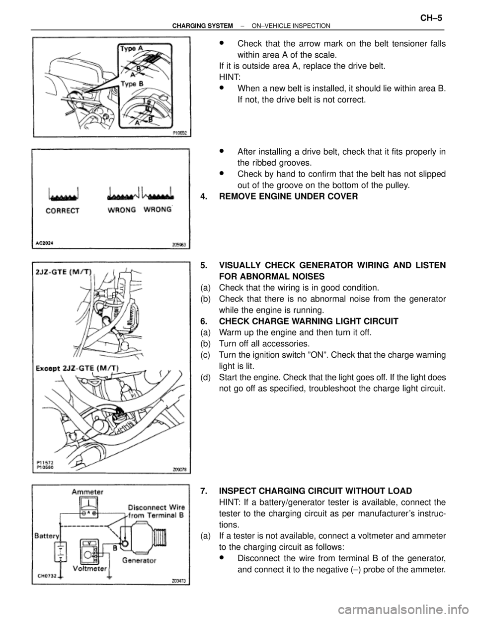
wCheck that the arrow mark on the belt tensioner falls
within area A of the scale.
If it is outside area A, replace the drive belt.
HINT:
wWhen a new belt is installed, it should lie within area B.
If not, the drive belt is not correct.
wAfter installing a drive belt, check that it fits properly in
the ribbed grooves.
wCheck by hand to confirm that the belt has not slipped
out of the groove on the bottom of the pulley.
4. REMOVE ENGINE UNDER COVER
5. VISUALLY CHECK GENERATOR WIRING AND LISTEN
FOR ABNORMAL NOISES
(a) Check that the wiring is in good condition.
(b) Check that there is no abnormal noise from the generator
while the engine is running.
6. CHECK CHARGE WARNING LIGHT CIRCUIT
(a) Warm up the engine and then turn it off.
(b) Turn off all accessories.
(c) Turn the ignition switch ºONº. Check that the charge warning
light is lit.
(d) Start the engine. Check that the light goes off. If the light does
not go off as specified, troubleshoot the charge light circuit.
7. INSPECT CHARGING CIRCUIT WITHOUT LOAD
HINT: If a battery/generator tester is available, connect the
tester to the charging circuit as per manufacturer's instruc-
tions.
(a) If a tester is not available, connect a voltmeter and ammeter
to the charging circuit as follows:
wDisconnect the wire from terminal B of the generator,
and connect it to the negative (±) probe of the ammeter.
± CHARGING SYSTEMON±VEHICLE INSPECTIONCH±5
Page 1043 of 2543
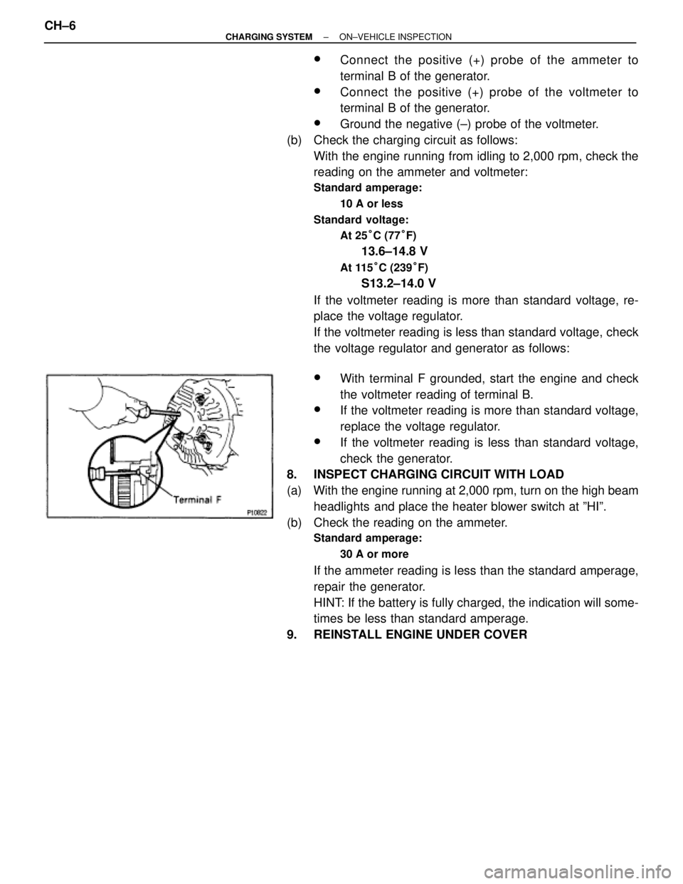
wConnect the positive (+) probe of the ammeter to
terminal B of the generator.
wConnect the positive (+) probe of the voltmeter to
terminal B of the generator.
wGround the negative (±) probe of the voltmeter.
(b) Check the charging circuit as follows:
With the engine running from idling to 2,000 rpm, check the
reading on the ammeter and voltmeter:
Standard amperage:
10 A or less
Standard voltage:
At 25°C (77°F)
13.6±14.8 V
At 115°C (239°F)
S13.2±14.0 V
If the voltmeter reading is more than standard voltage, re-
place the voltage regulator.
If the voltmeter reading is less than standard voltage, check
the voltage regulator and generator as follows:
wWith terminal F grounded, start the engine and check
the voltmeter reading of terminal B.
wIf the voltmeter reading is more than standard voltage,
replace the voltage regulator.
wIf the voltmeter reading is less than standard voltage,
check the generator.
8. INSPECT CHARGING CIRCUIT WITH LOAD
(a) With the engine running at 2,000 rpm, turn on the high beam
headlights and place the heater blower switch at ºHIº.
(b) Check the reading on the ammeter.
Standard amperage:
30 A or more
If the ammeter reading is less than the standard amperage,
repair the generator.
HINT: If the battery is fully charged, the indication will some-
times be less than standard amperage.
9. REINSTALL ENGINE UNDER COVER CH±6
± CHARGING SYSTEMON±VEHICLE INSPECTION
Page 1045 of 2543
GENERATOR REMOVAL
Installation is in the reverse order of removal.
1. REMOVE ENGINE UNDER COVER
2. 2JZ±GTE:
REMOVE NO.2 AIR TUBE FOR CAC
3. REMOVE NO.2 FAN SHROUD
4. 2JZ±GTE M/T:
REMOVE DRIVE BELT TENSIONER DAMPER
Torque: 20 NVm (200 kgfVcm, 14 ftVlbf)
5. REMOVE DRIVE BELT
6. REMOVE GENERATOR
(a) Disconnect the generator connector.
(b) Re mo ve th e rubber cap and nut, and disconnect the
generator wire.
(c) Disconnect the generator wire clamp from the wire clip on the
generator.
(d) A/T:
Remove the bolt and pipe clamp, and disconnect the 2 oil
cooler pipes from the generator.
(e) Remove the bolt, nut, pipe bracket and generator.
Torque: 37 NVm (380 kgfVcm, 27 ftVlbf)
CH±8± CHARGING SYSTEMGENERATOR
Page 1060 of 2543
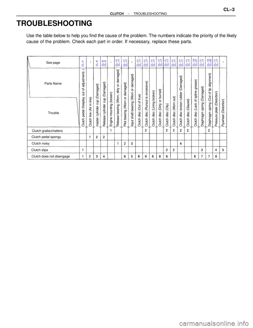
TROUBLESHOOTING
Use the table below to help you find the cause of the problem. The numbers indicate the priority of the likely
cause of the problem. Check each part in order. If necessary, replace these parts.
CL±4CL±6CL±11See page
Parts Name
Trouble
Clutch grabs/chatters
Clutch noisy
Clutch slips
Clutch pedal spongy
Clutch does not disengage
Clutch pedal (freeplay out of adjustment)Pilot bearing (Worn or damaged)Release bearing (Worn, dirty or damaged)Engine mounting (loosen)Release cylinder cup (Damaged)master cylinder cup (Damaged)Clutch line (Air in line)Clutch disc (Dirty or burred)Clutch disc (Oily)Clutch disc (Worn out)Clutch disc torsion rubber (Damaged)Clutch disc (Out of true)Input shaft bearing (Worn or damaged)Clutch disc (Lining broken)Clutch disc (Runout is excessive)Clutch disc (Lack of spline grease)Diaphragm spring (Damaged)Clutch disc (Glazed)Diaphragm spring (Out of tip alignment)Pressure plate (Distortion)Flywheel (Distortion)
CL±17CL±8CL±9CL±11CL±17CL±11CL±17CL±11CL±17CL±11CL±17CL±11CL±17CL±11CL±17CL±11CL±17CL±11CL±17CL±11CL±17CL±15CL±21CL±11CL±17CL±15CL±20CL±11CL±17
± CLUTCHTROUBLESHOOTINGCL±3
Page 1061 of 2543
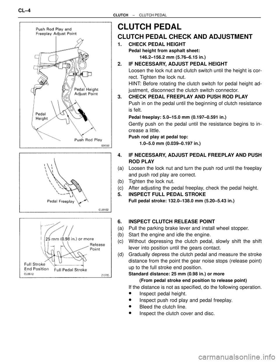
CLUTCH PEDAL
CLUTCH PEDAL CHECK AND ADJUSTMENT
1. CHECK PEDAL HEIGHT
Pedal height from asphalt sheet:
146.2±156.2 mm (5.76±6.15 in.)
2. IF NECESSARY, ADJUST PEDAL HEIGHT
Loosen the lock nut and clutch switch until the height is cor-
rect. Tighten the lock nut.
HINT: Before rotating the clutch switch for pedal height ad-
justment, disconnect the clutch switch connector.
3. CHECK PEDAL FREEPLAY AND PUSH ROD PLAY
Push in on the pedal until the beginning of clutch resistance
is felt.
Pedal freeplay: 5.0±15.0 mm (0.197±0.591 in.)
Gently push on the pedal until the resistance begins to in-
crease a little.
Push rod play at pedal top:
1.0±5.0 mm (0.039±0.197 in.)
4. IF NECESSARY, ADJUST PEDAL FREEPLAY AND PUSH
ROD PLAY
(a) Loosen the lock nut and turn the push rod until the freeplay
and push rod play are correct.
(b) Tighten the lock nut.
(c) After adjusting the pedal freeplay, check the pedal height.
5. INSPECT FULL PEDAL STROKE
Full pedal stroke: 132.0±138.0 mm (5.20±5.43 in.)
6. INSPECT CLUTCH RELEASE POINT
(a) Pull the parking brake lever and install wheel stopper.
(b) Start the engine and idle the engine.
(c) Without depressing the clutch pedal, slowly shift the shift
lever into position until the gears contact.
(d) Gradually depress the clutch pedal and measure the stroke
distance from the point the gear noise stops (release point)
up to the full stroke end position.
Standard distance: 25 mm (0.98 in.) or more
(From pedal stroke end position to release point)
If the distance is not as specified, do the following operation.
wInspect pedal height.
wInspect push rod play and pedal freeplay.
wBleed the clutch line.
wInspect the clutch cover and disc. CL±4
± CLUTCHCLUTCH PEDAL