Page 538 of 2543
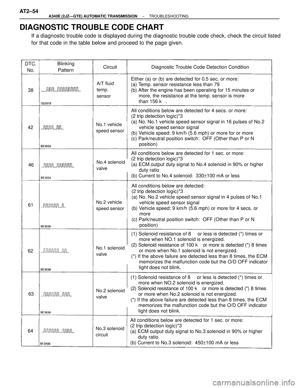
DTC.
No.Blinking
PatternCircuitDiagnostic Trouble Code Detection Condition
38
42
46
61
62
63
64
A/T fluid
temp.
sensor
No.1 vehicle
speed sensor
No.4 solenoid
valve
No.2 vehicle
speed sensor
No.1 solenoid
valve
No.2 solenoid
valve
No.3 solenoid
circuit
Either (a) or (b) are detected for 0.5 sec. or more:
(a) Temp. sensor resistance less than 79 �
(b) After the engine has been operating for 15 minutes or
more, the resistance at the temp. sensor is more
than 156 k��
All conditions below are detected for 4 secs. or more:
(2 trip detection logic)*3
(a) No. No.1 vehicle speed sensor signal in 16 pulses of No.2
vehicle speed sensor signal
(b) Vehicle speed: 9 km/h (5.6 mph) or more for or more
(c) Park/neutral position switch: OFF (Other than P or N
position)
All conditions below are detected for 1 sec. or more:
(2 trip detection logic)*3
(a) ECM output duty signal to No.4 solenoid in 90% or higher
duty ratio
(b) Current to No.4 solenoid: 330+100 mA or less
All conditions below are detected:
(2 trip detection logic)*3
(a) No. No.2 vehicle speed sensor signal in 4 pulses of No.1
vehicle speed sensor signal
(b) Vehicle speed: 9 km/h (5.6 mph) or more for 4 secs. or
more
(c) Park/neutral position switch: OFF (Other than P or N
position)
(1) Solenoid resistance of 8 ��or less is detected (*) times or
more when NO.1 solenoid is energized.
(2) Solenoid resistance of 100 k� or more is detected (*) 8 times
or more when No.1 solenoid is not energized.
(*) If the above failure are detected less than 8 times, the ECM
memorizes the malfunction code but the O/D OFF indicator
light does not blink.
(1) Solenoid resistance of 8 ��or less is detected (*) times or
more when NO.2 solenoid is energized.
(2) Solenoid resistance of 100 k� or more is detected (*) 8 times
or more when No.2 solenoid is not energized.
(*) If the above failure are detected less than 8 times, the ECM
memorizes the malfunction code but the O/D OFF indicator
light does not blink.
All conditions below are detected for 1 sec. or more:
(2 trip detection logic)*3
(a) ECM output duty signal to No.3 solenoid in 90% or higher
duty ratio
(b) Current to No.3 solenoid: 450+100 mA or less
DIAGNOSTIC TROUBLE CODE CHART
If a diagnostic trouble code is displayed during the diagnostic trouble code check, check the circuit listed
for that code in the table below and proceed to the page given. AT2±54
± A340E (2JZÐGTE) AUTOMATIC TRANSMISSIONTROUBLESHOOTING
Page 548 of 2543
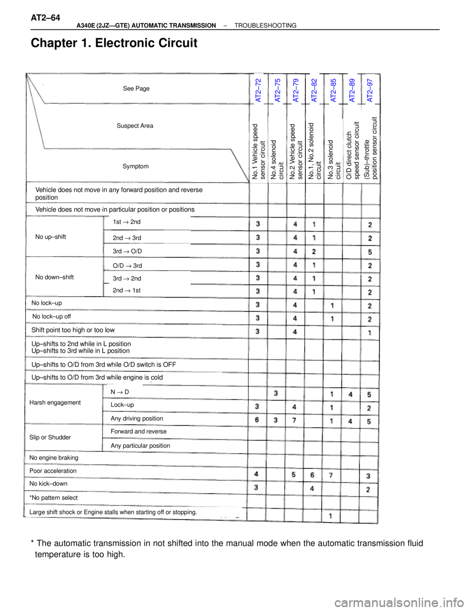
Chapter 1. Electronic Circuit
AT2±72AT2±75AT2±79AT2±82AT2±85AT2±89AT2±97
Suspect Area
Symptom
Vehicle does not move in any forward position and reverse
position
No up±shift
No down±shift
No lock±up
Vehicle does not move in particular position or positions
Harsh engagement
No engine braking
1st " 2nd
2nd " 3rd
3rd " O/D
O/D " 3rd
3rd " 2nd
2nd " 1st
N " D
Large shift shock or Engine stalls when starting off or stopping.
*No pattern select
No.1 Vehicle speed
sensor circuit
See Page
No lock±up off
Slip or Shudder
Poor acceleration
No kick±down
Lock±up
Any driving position
Forward and reverse
Any particular position
Shift point too high or too low
Up±shifts to 2nd while in L position
Up±shifts to 3rd while in L position
Up±shifts to O/D from 3rd while O/D switch is OFF
Up±shifts to O/D from 3rd while engine is cold
No.1, No.2 solenoidcircuitNo.2 Vehicle speed
sensor circuitNo.4 solenoid
circuitNo.3 solenoid
circuit(Sub)±throttle
position sensor circuitO/D direct clutch
speed sensor circuit
* The automatic transmission in not shifted into the manual mode when the automatic transmission fluid
temperature is too high. AT2±64
± A340E (2JZÐGTE) AUTOMATIC TRANSMISSIONTROUBLESHOOTING
Page 549 of 2543
AT2±101AT2±99AT2±103AT2±105AT2±108AT2±111EG±312AT2±60AT2±66AT2±68AT2±92BR±128AT2±70
Park/neutral position
switchPattern select switch
circuitStop light switch
circuitKick±down switch
circuitO/D switch O/D OFF
indicator light circuitEngine coolant temp.
sensor circuitO/D cancel signal
circuitECMNo.5 solenoid
circuitOFF±Vehicle repair
matrix chartOn±Vehicle repair
matrix chartTRAC ECUA/T fluid temp.
sensor circuit
± A340E (2JZÐGTE) AUTOMATIC TRANSMISSIONTROUBLESHOOTINGAT2±65
Page 550 of 2543
AT2±43
Suspect Area
Symptom
Vehicle does not move in any forward position and reverse
No up±shift
No down±shift
No lock±up or No lock±up off
Vehicle does not move in R position
Harsh engagement
1st
1st " 2nd
2nd " 3rd
3rd " O/D
O/D " 3rd
3rd " 2nd
2nd " 1st
N " D
No engine braking
Transmission
control rod
Slip or Shudder
2nd
No kick±down
Lock±up
Forward and Reverse
Particular position
Manual valveParking lock pawlOil strainer1±2 shift valve2±3 shift valve
N " R
N " L
1st " 2nd (D position)
1st " 2nd " 3rd " O/D
2nd "3rd
3rd " O/D
1st " 2nd (2 position)
O/D " 3rd
Vehicle does not move in any particular position or positions
(except R position)
Reverse control
valve
See Page
Chapter 2. On±Vehicle Repair
(��: A340E, A340F, A340H AUTOMATIC TRANSMISSION Repair Manual Pub. No.RM391U) AT2±66
± A340E (2JZÐGTE) AUTOMATIC TRANSMISSIONTROUBLESHOOTING
Page 552 of 2543
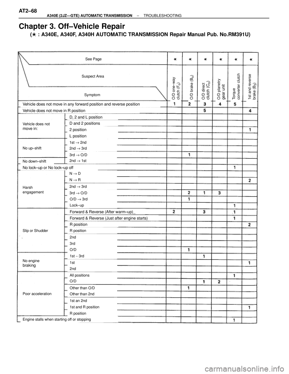
Suspect Area
Symptom
See Page
Vehicle does not move in any forward position and reverse position
No up±shift
No down±shift
Vehicle does not move in R position
1st " 2nd
2nd " 3rd
3rd " O/D
O/D " 3rd
3rd " O/D
2nd " 1st
2nd " 3rd
N " R
N " D
Lock±up
R position
2nd
3rd
1st ~ 3rd
O/D
1st
2nd
All positions
O/D
Other than O/D
Other than 2nd
1st an 2nd
R position
1st and R position
Engine stalls when starting off or stopping
Poor acceleration
No enginebraking
Slip or Shudder
Harsh
engagement
Vehicle does notmove in:
No lock±up or No lock±up off
Forward & Reverse (After warm±up)_
Forward & Reverse (Just after engine starts)
R position
D, 2 and L position
D and 2 positions
2 position
L position
O/D one±way
clutch (F
o)
O/D planetrygear unitO/D directclutch (C
o)
O/D brake (B
o)
1st and reverse
brake (B
3)
Torque
converter clutch
Chapter 3. Off±Vehicle Repair
(� : A340E, A340F, A340H AUTOMATIC TRANSMISSION Repair Manual Pub. No.RM391U) AT2±68
± A340E (2JZÐGTE) AUTOMATIC TRANSMISSIONTROUBLESHOOTING
Page 554 of 2543
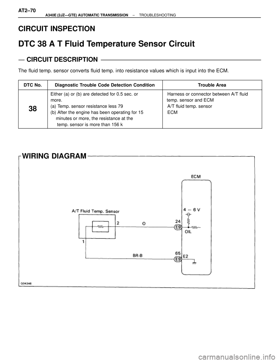
WIRING DIAGRAM CIRCUIT INSPECTION
DTC 38 A T Fluid Temperature Sensor Circuit
CIRCUIT DESCRIPTION
The fluid temp. sensor converts fluid temp. into resistance values which is input into the ECM.
����� �����DTC No.������������������ ������������������Diagnostic Trouble Code Detection Condition��������������� ���������������Trouble Area
����� �
���� �
���� �
���� �
���� �
���� �����
38
������������������ �
����������������� �
����������������� �
����������������� �
����������������� �
����������������� ������������������
Either (a) or (b) are detected for 0.5 sec. or
more.
(a) Temp. sensor resistance less 79 �
(b) After the engine has been operating for 15
minutes or more, the resistance at the
temp. sensor is more than 156 k ���������������� �
�������������� �
�������������� �
�������������� �
�������������� �
�������������� ���������������
� Harness or connector between A/T fluid
temp. sensor and ECM
� A/T fluid temp. sensor
� ECM
AT2±70± A340E (2JZÐGTE) AUTOMATIC TRANSMISSIONTROUBLESHOOTING
Page 556 of 2543
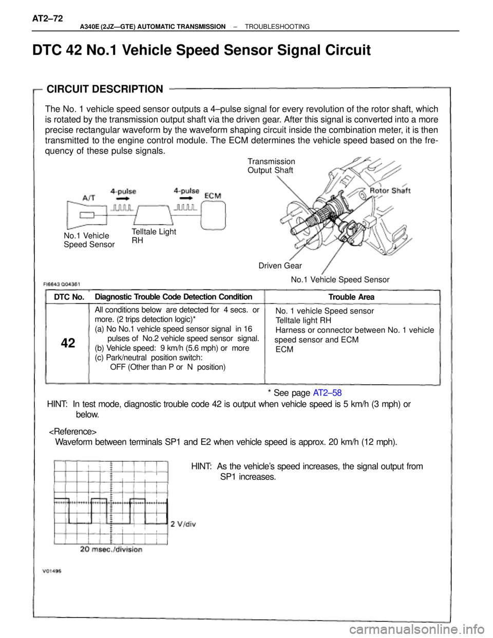
CIRCUIT DESCRIPTION
Transmission
Output Shaft
No.1 Vehicle
Speed Sensor
The No. 1 vehicle speed sensor outputs a 4±pulse signal for every revolution of the rotor shaft, which
is rotated by the transmission output shaft via the driven gear. After this signal is converted into a more
precise rectangular waveform by the waveform shaping circuit inside the combination meter, it is then
transmitted to the engine control module. The ECM determines the vehicle speed based on the fre-
quency of these pulse signals.
Diagnostic Trouble Code Detection ConditionDTC No.Trouble Area
42
� No. 1 vehicle Speed sensor
� Telltale light RH
� Harness or connector between No. 1 vehicle
speed sensor and ECM
� ECMAll conditions below are detected for 4 secs. or
more. (2 trips detection logic)*
(a) No No.1 vehicle speed sensor signal in 16
pulses of No.2 vehicle speed sensor signal.
(b) Vehicle speed: 9 km/h (5.6 mph) or more
(c) Park/neutral position switch:
OFF (Other than P or N position)
HINT: In test mode, diagnostic trouble code 42 is output when vehicle speed is 5 km/h (3 mph) or
below.
� Waveform between terminals SP1 and E2 when vehicle speed is approx. 20 km/h (12 mph).
HINT: As the vehicle's speed increases, the signal output from
SP1 increases.
* See page AT2±58
Driven Gear
No.1 Vehicle Speed Sensor
Telltale Light
RH
DTC 42 No.1 Vehicle Speed Sensor Signal Circuit
AT2±72± A340E (2JZÐGTE) AUTOMATIC TRANSMISSIONTROUBLESHOOTING
Page 559 of 2543
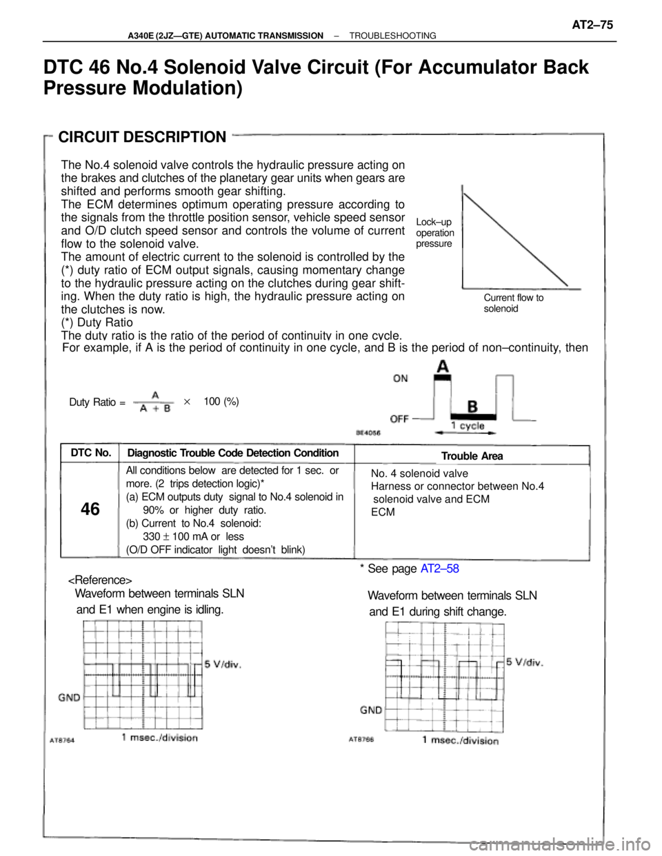
The No.4 solenoid valve controls the hydraulic pressure acting on
the brakes and clutches of the planetary gear units when gears are
shifted and performs smooth gear shifting.
The ECM determines optimum operating pressure according to
the signals from the throttle position sensor, vehicle speed sensor
and O/D clutch speed sensor and controls the volume of current
flow to the solenoid valve.
The amount of electric current to the solenoid is controlled by the
(*) duty ratio of ECM output signals, causing momentary change
to the hydraulic pressure acting on the clutches during gear shift-
ing. When the duty ratio is high, the hydraulic pressure acting on
the clutches is now.
(*) Duty Ratio
The duty ratio is the ratio of the period of continuity in one cycle.
For example, if A is the period of continuity in one cycle, and B is the period of non±continuity, then
Diagnostic Trouble Code Detection ConditionDTC No.Trouble Area
46
� No. 4 solenoid valve
� Harness or connector between No.4
solenoid valve and ECM
� ECMAll conditions below are detected for 1 sec. or
more. (2 trips detection logic)*
(a) ECM outputs duty signal to No.4 solenoid in
90% or higher duty ratio.
(b) Current to No.4 solenoid:
330 + 100 mA or less
(O/D OFF indicator light doesn't blink)
* See page AT2±58
� Waveform between terminals SLN
and E1 when engine is idling.� Waveform between terminals SLN
and E1 during shift change.
Lock±up
operation
pressure
Current flow to
solenoid
Duty Ratio =
CIRCUIT DESCRIPTION
��100 (%)
DTC 46 No.4 Solenoid Valve Circuit (For Accumulator Back
Pressure Modulation)
± A340E (2JZÐGTE) AUTOMATIC TRANSMISSIONTROUBLESHOOTINGAT2±75