Page 506 of 2543
TRANSMISSION REMOVAL
Installation is in the reverse order of removal.
INSTALLATION HINT: After installation, fill A/T fluid and
check fluid level. (See page AT2±42)
1. REMOVE LEVEL GAUGE
2. REMOVE FILLER PIPE
Remove the bolt and filler pipe.
3. REMOVE ENGINE UNDER COVER
4. DISCONNECT OXYGEN SENSOR
(a) Remove the 2 nuts.
(b) Remove the cover and the sensor.
5. REMOVE EXHAUST PIPE
(a) Remove the 2 nuts and 4 bolts.
(b) Disconnect the rings from the exhaust pipe brackets.
(c) Remove the exhaust pipe, gasket and bracket.
Torque:
Bracket X Transmission housing:
37 NVm (380 kgfVcm, 27 ftVlbf)
No.2 exhaust pipe X Center exhaust pipe:
58 NVm (590 kgfVcm, 43 ftVlbf)
6. REMOVE HEAT INSULATOR
Torque: 5.4 NVm (55 kgfVcm, 48 in.Vlbf)
AT2±22± A340E (2JZÐGTE) AUTOMATIC TRANSMISSIONASSEMBLY REMOVAL AND INSTALLATION
Page 509 of 2543
(b) Turn the crankshaft to gain access and remove the 6 bolts.
Torque: 33 NVm (340 kgfVcm, 25 ftVlbf)
16. SET TRANSMISSION JACK
17. SUPPORT ENGINE
NOTICE: Use a wooden block so not to damage the en-
gine oil pan.
18. REMOVE TRANSMISSION REAR SUPPORT
Torque: 25 NVm (250 kgfVcm, 19 ftVlbf)
19. REMOVE 4 WIRE HARNESS CLAMPS
Lower the transmission and remove the 4 wire harness
clamps from the retainer.
20. REMOVE STARTER AND TRANSMISSION SET BOLTS
Torque:
17 mm head bolt:
72 NVm (730 kgfVcm, 53 ftVlbf)
14 mm head bolt:
37 NVm (380 kgfVcm, 27 ftVlbf)
± A340E (2JZÐGTE) AUTOMATIC TRANSMISSIONASSEMBLY REMOVAL AND INSTALLATIONAT2±25
Page 510 of 2543
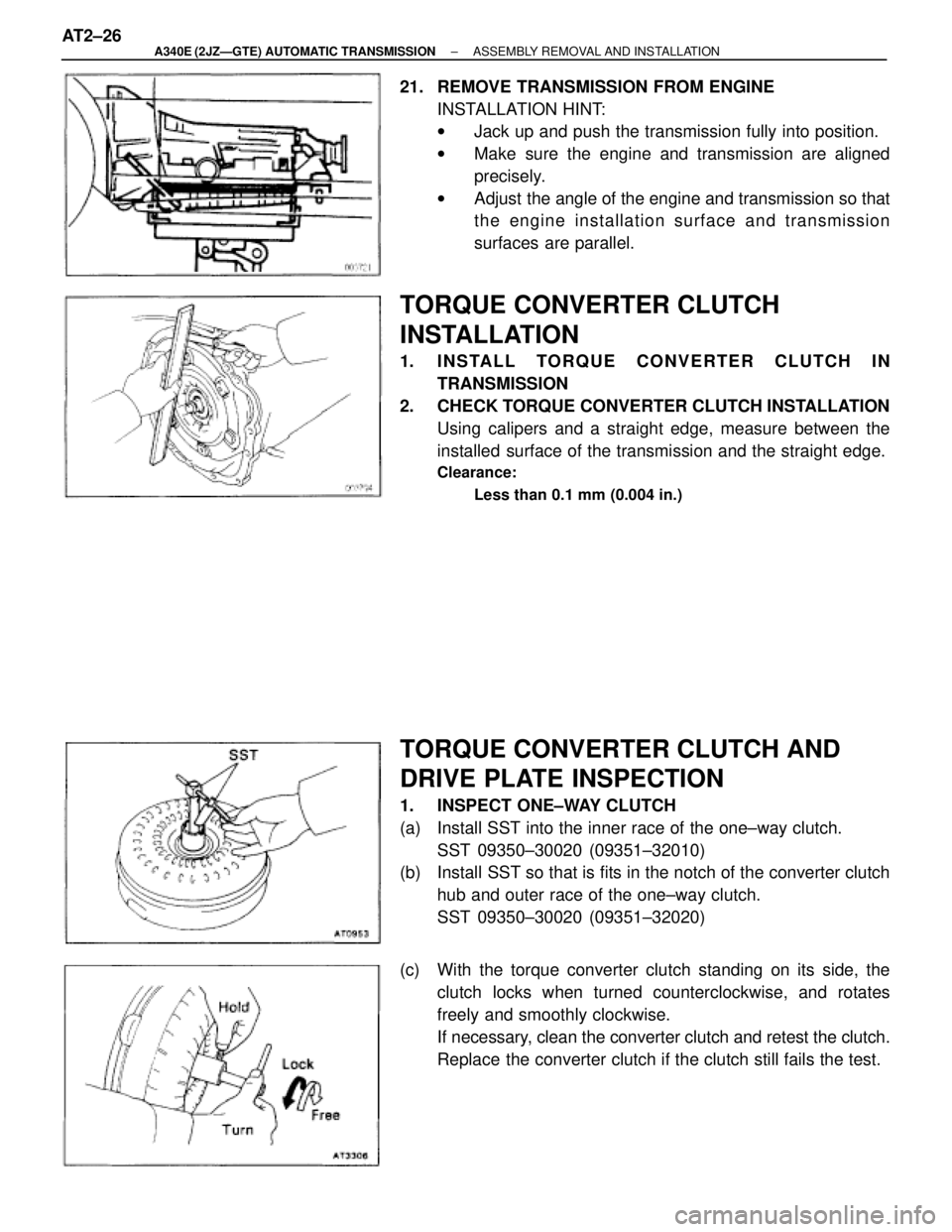
21. REMOVE TRANSMISSION FROM ENGINE
INSTALLATION HINT:
wJack up and push the transmission fully into position.
wMake sure the engine and transmission are aligned
precisely.
wAdjust the angle of the engine and transmission so that
the engine installation surface and transmission
surfaces are parallel.
TORQUE CONVERTER CLUTCH
INSTALLATION
1. INSTALL TORQUE CONVERTER CLUTCH IN
TRANSMISSION
2. CHECK TORQUE CONVERTER CLUTCH INSTALLATION
Using calipers and a straight edge, measure between the
installed surface of the transmission and the straight edge.
Clearance:
Less than 0.1 mm (0.004 in.)
TORQUE CONVERTER CLUTCH AND
DRIVE PLATE INSPECTION
1. INSPECT ONE±WAY CLUTCH
(a) Install SST into the inner race of the one±way clutch.
SST 09350±30020 (09351±32010)
(b) Install SST so that is fits in the notch of the converter clutch
hub and outer race of the one±way clutch.
SST 09350±30020 (09351±32020)
(c) With the torque converter clutch standing on its side, the
clutch locks when turned counterclockwise, and rotates
freely and smoothly clockwise.
If necessary, clean the converter clutch and retest the clutch.
Replace the converter clutch if the clutch still fails the test. AT2±26
± A340E (2JZÐGTE) AUTOMATIC TRANSMISSIONASSEMBLY REMOVAL AND INSTALLATION
Page 518 of 2543
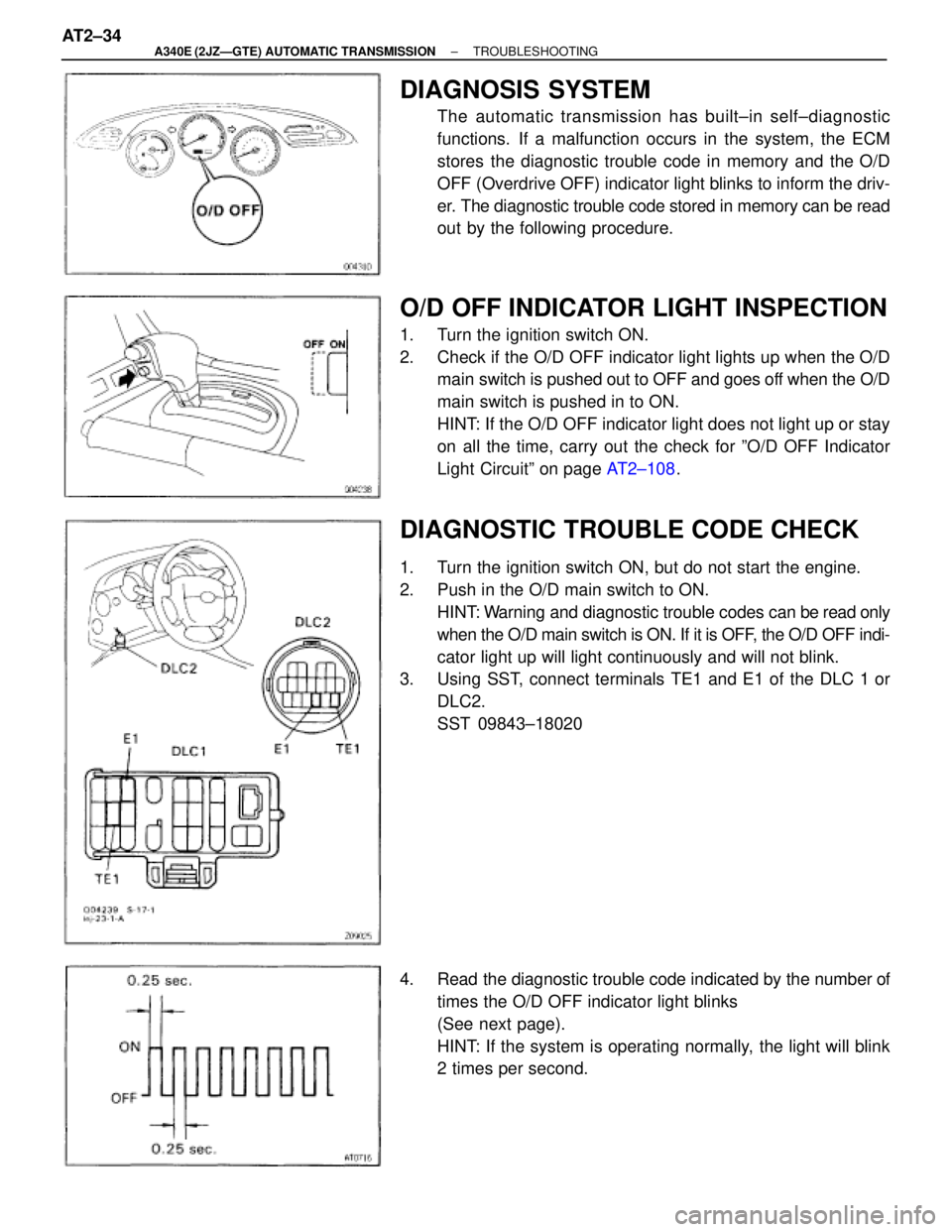
DIAGNOSIS SYSTEM
The automatic transmission has built±in self±diagnostic
functions. If a malfunction occurs in the system, the ECM
stores the diagnostic trouble code in memory and the O/D
OFF (Overdrive OFF) indicator light blinks to inform the driv-
er. The diagnostic trouble code stored in memory can be read
out by the following procedure.
O/D OFF INDICATOR LIGHT INSPECTION
1. Turn the ignition switch ON.
2. Check if the O/D OFF indicator light lights up when the O/D
main switch is pushed out to OFF and goes off when the O/D
main switch is pushed in to ON.
HINT: If the O/D OFF indicator light does not light up or stay
on all the time, carry out the check for ºO/D OFF Indicator
Light Circuitº on page AT2±108.
DIAGNOSTIC TROUBLE CODE CHECK
1. Turn the ignition switch ON, but do not start the engine.
2. Push in the O/D main switch to ON.
HINT: Warning and diagnostic trouble codes can be read only
when the O/D main switch is ON. If it is OFF, the O/D OFF indi-
cator light up will light continuously and will not blink.
3. Using SST, connect terminals TE1 and E1 of the DLC 1 or
DLC2.
SST 09843±18020
4. Read the diagnostic trouble code indicated by the number of
times the O/D OFF indicator light blinks
(See next page).
HINT: If the system is operating normally, the light will blink
2 times per second. AT2±34
± A340E (2JZÐGTE) AUTOMATIC TRANSMISSIONTROUBLESHOOTING
Page 520 of 2543
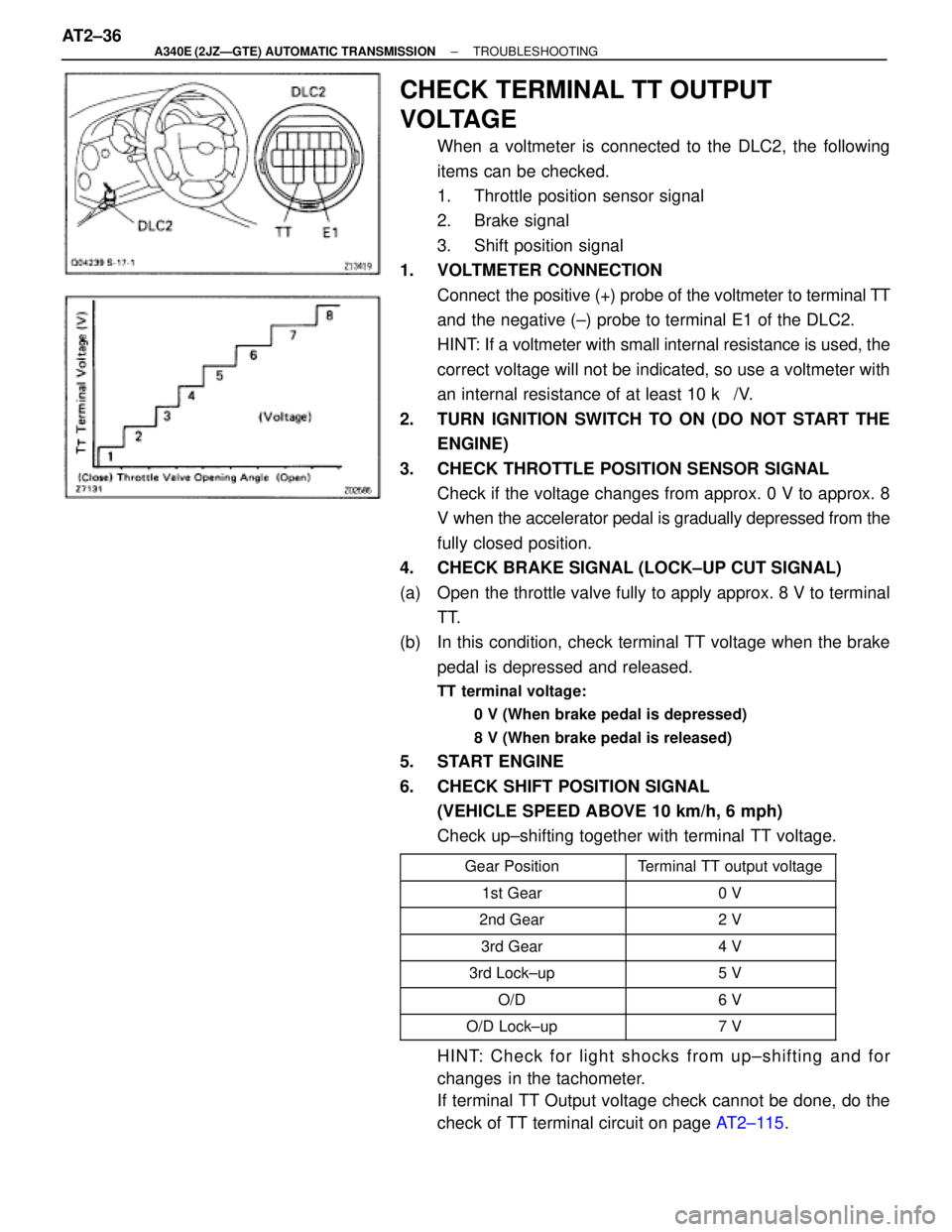
CHECK TERMINAL TT OUTPUT
VOLTAGE
When a voltmeter is connected to the DLC2, the following
items can be checked.
1. Throttle position sensor signal
2. Brake signal
3. Shift position signal
1. VOLTMETER CONNECTION
Connect the positive (+) probe of the voltmeter to terminal TT
and the negative (±) probe to terminal E1 of the DLC2.
HINT: If a voltmeter with small internal resistance is used, the
correct voltage will not be indicated, so use a voltmeter with
an internal resistance of at least 10 k�/V.
2. TURN IGNITION SWITCH TO ON (DO NOT START THE
ENGINE)
3. CHECK THROTTLE POSITION SENSOR SIGNAL
Check if the voltage changes from approx. 0 V to approx. 8
V when the accelerator pedal is gradually depressed from the
fully closed position.
4. CHECK BRAKE SIGNAL (LOCK±UP CUT SIGNAL)
(a) Open the throttle valve fully to apply approx. 8 V to terminal
TT.
(b) In this condition, check terminal TT voltage when the brake
pedal is depressed and released.
TT terminal voltage:
0 V (When brake pedal is depressed)
8 V (When brake pedal is released)
5. START ENGINE
6. CHECK SHIFT POSITION SIGNAL
(VEHICLE SPEED ABOVE 10 km/h, 6 mph)
Check up±shifting together with terminal TT voltage.
����������� �����������Gear Position��������� ���������Terminal TT output voltage����������� �����������1st Gear��������� ���������0 V����������� �
���������� �����������2nd Gear
��������� �
�������� ���������2 V
����������� �����������3rd Gear��������� ���������4 V
����������� �����������3rd Lock±up��������� ���������5 V
����������� �����������O/D��������� ���������6 V
����������� �����������O/D Lock±up��������� ���������7 V
HINT: Check for light shocks from up±shifting and for
changes in the tachometer.
If terminal TT Output voltage check cannot be done, do the
check of TT terminal circuit on page AT2±115. AT2±36
± A340E (2JZÐGTE) AUTOMATIC TRANSMISSIONTROUBLESHOOTING
Page 522 of 2543
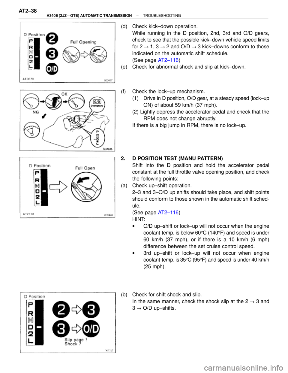
(d) Check kick±down operation.
While running in the D position, 2nd, 3rd and O/D gears,
check to see that the possible kick±down vehicle speed limits
for 2
" 1, 3 " 2 and O/D " 3 kick±downs conform to those
indicated on the automatic shift schedule.
(See page AT2±116)
(e) Check for abnormal shock and slip at kick±down.
(f) Check the lock±up mechanism.
(1) Drive in D position, O/D gear, at a steady speed (lock±up
ON) of about 59 km/h (37 mph).
(2) Lightly depress the accelerator pedal and check that the
RPM does not change abruptly.
If there is a big jump in RPM, there is no lock±up.
2. D POSITION TEST (MANU PATTERN)
Shift into the D position and hold the accelerator pedal
constant at the full throttle valve opening position, and check
the following points:
(a) Check up±shift operation.
2±3 and 3±O/D up shifts should take place, and shift points
should conform to those shown in the automatic shift sched-
ule.
(See page AT2±116)
HINT:
wO/D up±shift or lock±up will not occur when the engine
coolant temp. is below 605C (1405F) and speed is under
60 km/h (37 mph), or if there is a 10 km/h (6 mph)
difference between the set cruise control speed.
w3rd up±shift or lock±up will not occur when engine
coolant temp. is 355C (955F) and speed is under 40 km/h
(25 mph).
(b) Check for shift shock and slip.
In the same manner, check the shock slip at the 2
" 3 and
3
" O/D up±shifts. AT2±38
± A340E (2JZÐGTE) AUTOMATIC TRANSMISSIONTROUBLESHOOTING
Page 523 of 2543
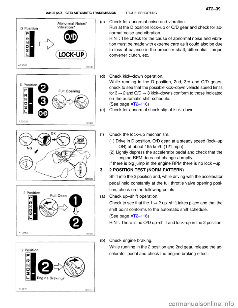
(c) Check for abnormal noise and vibration.
Run at the D position lock±up or O/D gear and check for ab-
normal noise and vibration.
HINT: The check for the cause of abnormal noise and vibra-
tion must be made with extreme care as it could also be due
to loss of balance in the propeller shaft, differential, torque
converter clutch, etc.
(d) Check kick±down operation.
While running in the D position, 2nd, 3rd and O/D gears,
check to see that the possible kick±down vehicle speed limits
for 3
" 2 and O/D " 3 kick±downs conform to those indicated
on the automatic shift schedule.
(See page AT2±116)
(e) Check for abnormal shock slip at kick±down.
(f) Check the lock±up mechanism.
(1) Drive in D position, O/D gear, at a steady speed (lock±up
ON) of about 195 km/h (121 mph).
(2) Lightly depress the accelerator pedal and check that the
engine RPM does not change abruptly.
If there is big jump in the engine RPM there is no lock ±up.
3. 2 POSITION TEST (NORM PATTERN)
Shift into the 2 position and, while driving with the accelerator
pedal held constantly at the full throttle valve opening posi-
tion, check on the following points:
(a) Check up±shift operation.
Check to see that the 1
" 2 up±shift takes place and that the
shift point conforms to the automatic shift schedule.
(See page AT2±116)
HINT: There is no O/D up±shift and lock±up in the 2 position.
(b) Check engine braking.
While running in the 2 position and 2nd gear, release the ac-
celerator pedal and check the engine braking effect.
± A340E (2JZÐGTE) AUTOMATIC TRANSMISSIONTROUBLESHOOTINGAT2±39
Page 524 of 2543
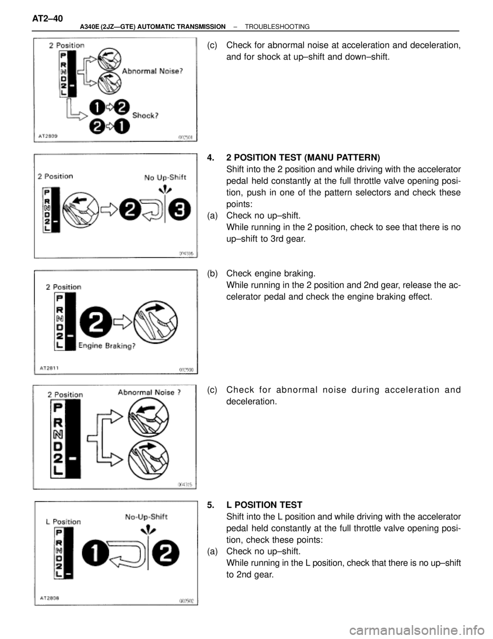
(c) Check for abnormal noise at acceleration and deceleration,
and for shock at up±shift and down±shift.
4. 2 POSITION TEST (MANU PATTERN)
Shift into the 2 position and while driving with the accelerator
pedal held constantly at the full throttle valve opening posi-
tion, push in one of the pattern selectors and check these
points:
(a) Check no up±shift.
While running in the 2 position, check to see that there is no
up±shift to 3rd gear.
(b) Check engine braking.
While running in the 2 position and 2nd gear, release the ac-
celerator pedal and check the engine braking effect.
(c) C h e c k f o r abnormal noise during acceleration and
deceleration.
5. L POSITION TEST
Shift into the L position and while driving with the accelerator
pedal held constantly at the full throttle valve opening posi-
tion, check these points:
(a) Check no up±shift.
While running in the L position, check that there is no up±shift
to 2nd gear. AT2±40
± A340E (2JZÐGTE) AUTOMATIC TRANSMISSIONTROUBLESHOOTING