Page 127 of 2248

G2M0213
C: INSTALLATION
Installation is in the reverse order of removal.
CAUTION:
�Replace gasket with a new one.
�When installing engine coolant pump, tighten bolts
in two stages in numerical sequence as shown in fig-
ure.
Tightening torque:
10
+4
�0N⋅m (1.0+0.4
�0kg-m, 7.2+2.9
�0ft-lb)
G2M0214
3. Thermostat
A: REMOVAL AND INSTALLATION
1) Drain engine coolant.
Set container under the vehicle, and remove drain cock
from radiator.
2) Disconnect radiator outlet hose from thermostat cover.
3) Remove thermostat cover and gasket, and pull out the
thermostat.
G2M0227
4) Install the thermostat in the intake manifold, and install
the thermostat cover together with a gasket.
CAUTION:
�When reinstalling the thermostat, use a new gasket.
�The thermostat must be installed with the jiggle pin
upward.
�In this time, set the jiggle pin of thermostat for front
side.
G2M0215
B: INSPECTION
Replace the thermostat if the valve does not close com-
pletely at an ambient temperature or if the following test
shows unsatisfactory results.
Immerse the thermostat and a thermometer in water. Raise
water temperature gradually, and measure the temperature
and valve lift when the valve begins to open and when the
valve is fully opened. During the test, agitate the water for
even temperature distribution. The measurement should
be to the specification.
Starts to open:
76.0—80.0°C (169—176°F)
Fully opens:
91°C (196°F)
11
2-5SERVICE PROCEDURE
2. Engine Coolant Pump - 3. Thermostat
Page 135 of 2248
B2M0138
5) Disconnect heater inlet hose.
B2M0139
6) Disconnect radiator inlet hose from engine coolant pipe.
B2M0141
7) Remove bolts which install engine coolant pipe on cyl-
inder block.
B2M0141
B: INSTALLATION
1) Install engine coolant pipe on cylinder block.
Tightening torque:
6.4±0.5 N⋅m (0.65±0.05 kg-m, 4.7±0.4 ft-lb)
CAUTION:
Use a new O-ring.
B2M0139
2) Connect radiator inlet hose.
17
2-5SERVICE PROCEDURE
7. Engine Coolant Pipe
Page 153 of 2248

1. Collector Chamber and Intake
Manifold
B2M0338A
�1Intake manifold gasket RH
�
2Intake manifold gasket LH
�
3Fuel injector pipe insulator
�
4Fuel injector pipe
�
5O-ring A
�
6O-ring B
�
7Fuel injector
�
8Insulator
�
9Fuel injector cap
�
10Gasket
�
11Engine coolant hose B
�
12Air by-pass hose
�
13Idle air control solenoid valve
�
14Engine coolant hose A�
15Nipple (AT model)
�
16Plug
�
17PCV valve
�
18Purge control solenoid valve
�
19Nipple
�
20BPT
�
21BPT holder bracket
�
22Back pressure hose
�
23EGR vacuum hose A
�
24EGR vacuum pipe
�
25EGR vacuum hose C
�
26EGR valve
�
27Gasket
�
28EGR vacuum hose B�
29EGR solenoid valve
�
30EGR pipe
�
31Intake manifold
Tightening torque: N⋅m (kg-m, ft-lb)
T1: 3.4±0.5 (0.35±0.05, 2.5±0.4)
T2: 6.4±0.5 (0.65±0.05, 4.7±0.4)
T3: 16±1.5 (1.6±0.15, 11.6±1.1)
T4: 19±1 (1.9±0.1, 13.7±0.7)
T5: 19±1.5 (1.9±0.15, 13.7±1.1)
T6: 23±3 (2.3±0.3, 16.6±2.2)
T7: 25±2 (2.5±0.2, 18.1±1.4)
T8: 34±2 (3.5±0.2, 25.3±1.4)
2
2-7COMPONENT PARTS
1. Collector Chamber and Intake Manifold
Page 154 of 2248
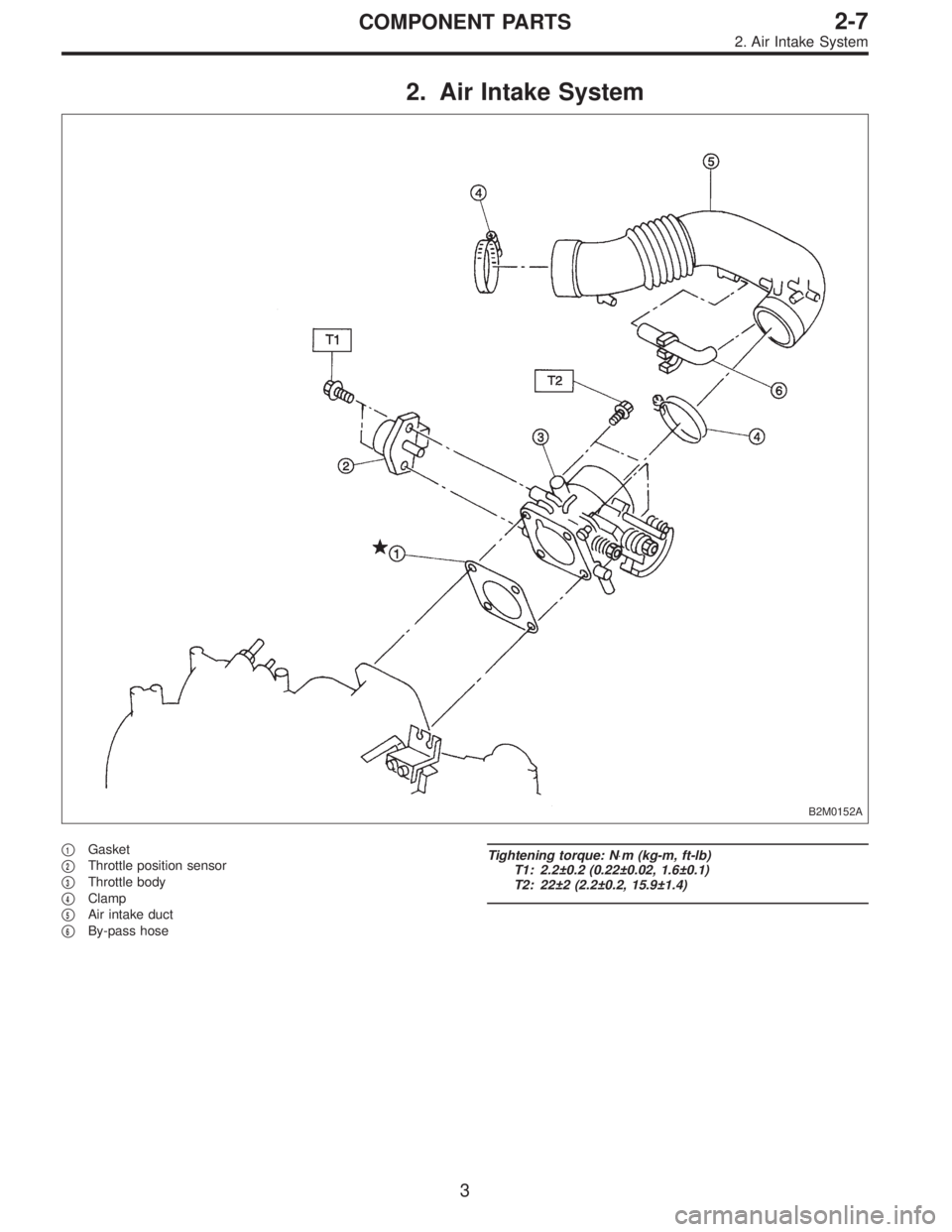
2. Air Intake System
B2M0152A
�1Gasket
�
2Throttle position sensor
�
3Throttle body
�
4Clamp
�
5Air intake duct
�
6By-pass hose
Tightening torque: N⋅m (kg-m, ft-lb)
T1: 2.2±0.2 (0.22±0.02, 1.6±0.1)
T2: 22±2 (2.2±0.2, 15.9±1.4)
3
2-7COMPONENT PARTS
2. Air Intake System
Page 155 of 2248
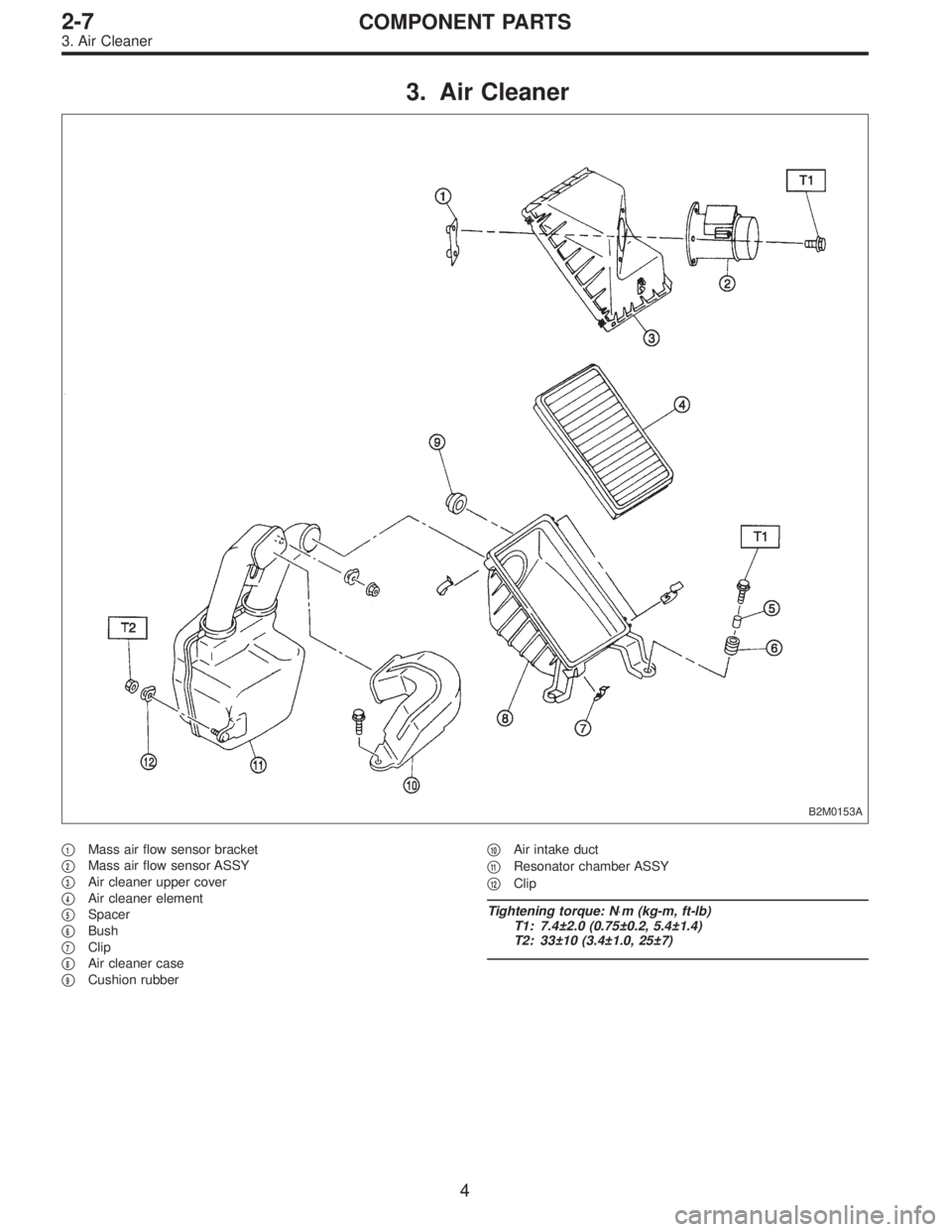
3. Air Cleaner
B2M0153A
�1Mass air flow sensor bracket
�
2Mass air flow sensor ASSY
�
3Air cleaner upper cover
�
4Air cleaner element
�
5Spacer
�
6Bush
�
7Clip
�
8Air cleaner case
�
9Cushion rubber�
10Air intake duct
�
11Resonator chamber ASSY
�
12Clip
Tightening torque: N⋅m (kg-m, ft-lb)
T1: 7.4±2.0 (0.75±0.2, 5.4±1.4)
T2: 33±10 (3.4±1.0, 25±7)
4
2-7COMPONENT PARTS
3. Air Cleaner
Page 157 of 2248
B2M0154
2. Mass Air Flow Sensor
A: REMOVAL AND INSTALLATION
1) Remove air intake duct.
G2M0305
2) Disconnect connector from mass air flow sensor.
G2M0390
3) Remove air cleaner upper cover.
G2M0393
4) Remove mass air flow sensor from air cleaner upper
cover.
5) Installation is in the reverse order of removal.
Tightening torque:
7.4±2.0 N⋅m (0.75±0.2 kg-m, 5.4±1.4 ft-lb)
6
2-7SERVICE PROCEDURE
2. Mass Air Flow Sensor
Page 158 of 2248
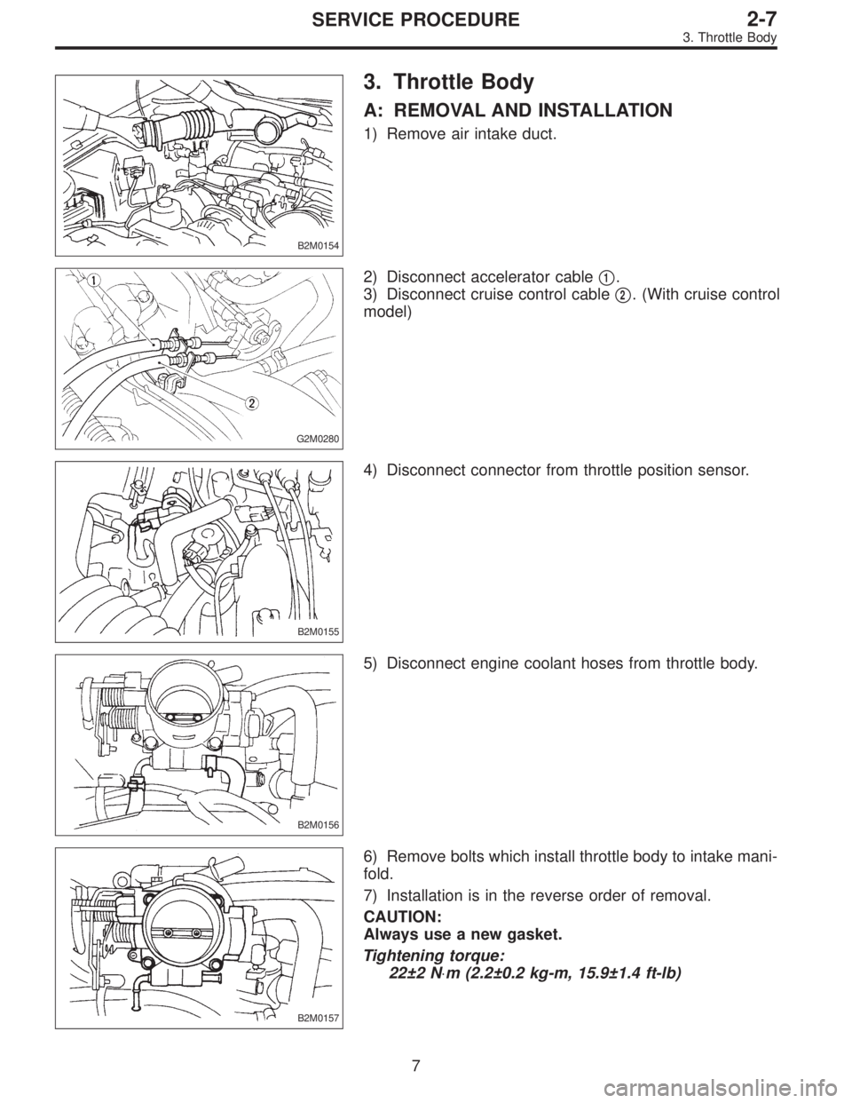
B2M0154
3. Throttle Body
A: REMOVAL AND INSTALLATION
1) Remove air intake duct.
G2M0280
2) Disconnect accelerator cable�1.
3) Disconnect cruise control cable�
2. (With cruise control
model)
B2M0155
4) Disconnect connector from throttle position sensor.
B2M0156
5) Disconnect engine coolant hoses from throttle body.
B2M0157
6) Remove bolts which install throttle body to intake mani-
fold.
7) Installation is in the reverse order of removal.
CAUTION:
Always use a new gasket.
Tightening torque:
22±2 N⋅m (2.2±0.2 kg-m, 15.9±1.4 ft-lb)
7
2-7SERVICE PROCEDURE
3. Throttle Body
Page 164 of 2248
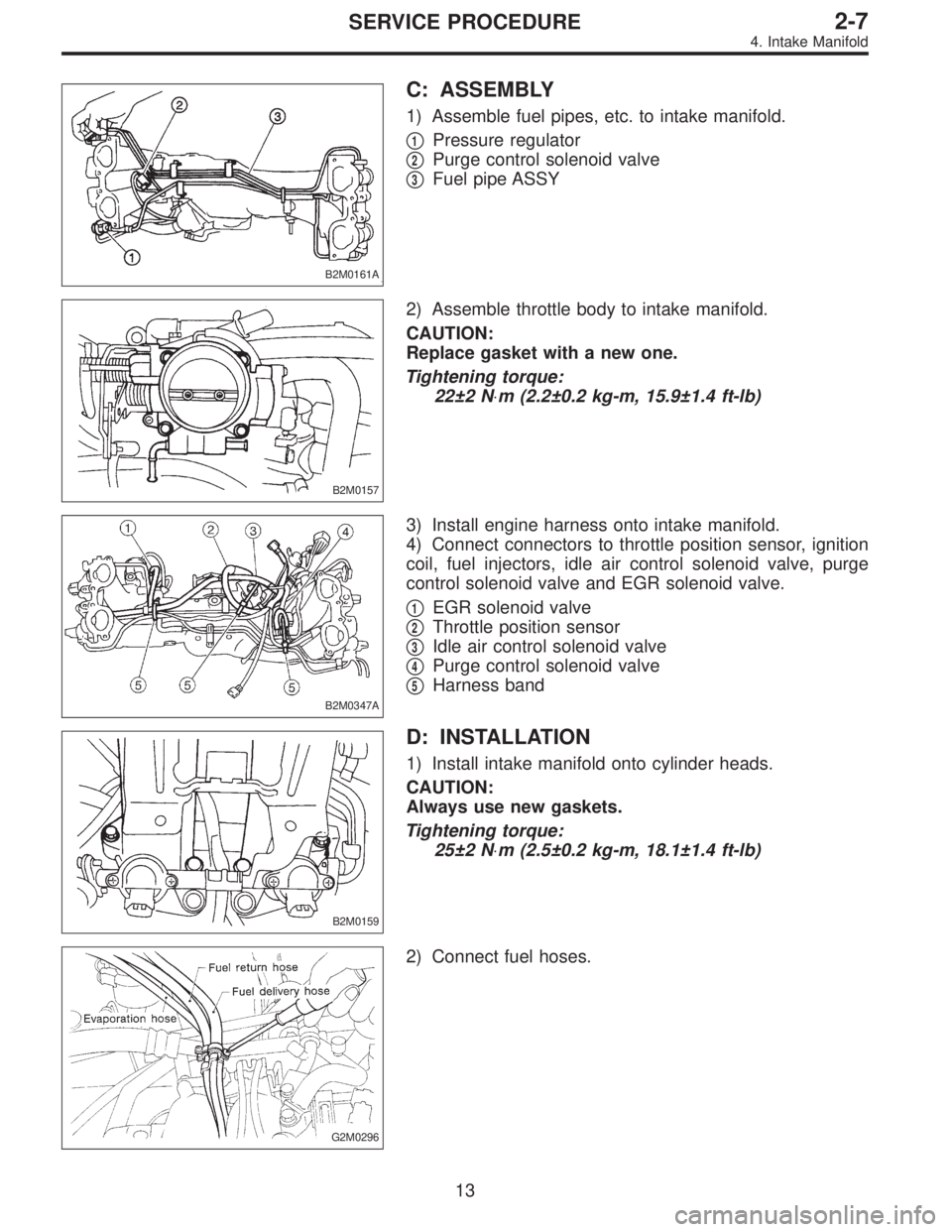
B2M0161A
C: ASSEMBLY
1) Assemble fuel pipes, etc. to intake manifold.
�
1Pressure regulator
�
2Purge control solenoid valve
�
3Fuel pipe ASSY
B2M0157
2) Assemble throttle body to intake manifold.
CAUTION:
Replace gasket with a new one.
Tightening torque:
22±2 N⋅m (2.2±0.2 kg-m, 15.9±1.4 ft-lb)
B2M0347A
3) Install engine harness onto intake manifold.
4) Connect connectors to throttle position sensor, ignition
coil, fuel injectors, idle air control solenoid valve, purge
control solenoid valve and EGR solenoid valve.
�
1EGR solenoid valve
�
2Throttle position sensor
�
3Idle air control solenoid valve
�
4Purge control solenoid valve
�
5Harness band
B2M0159
D: INSTALLATION
1) Install intake manifold onto cylinder heads.
CAUTION:
Always use new gaskets.
Tightening torque:
25±2 N⋅m (2.5±0.2 kg-m, 18.1±1.4 ft-lb)
G2M0296
2) Connect fuel hoses.
13
2-7SERVICE PROCEDURE
4. Intake Manifold
 Disconnect heater inlet hose.
B2M0139
6) Disconnect radiator inlet hose from engine coolant pipe.
B2M0141
7) Remove bolts which install engine coolant pipe on cyl-
inder block.
B2M0141
B: I")
 Remove air intake duct.
G2M0305
2) Disconnect connector from mass air flow sensor.
G2M0390
3) Remove air cleaner upper cover.
G2M0393
4)")