Page 1723 of 2248
 Dismount brake as outlined in manual to gain access to
ABS sensor and tone wheel for inspection.
2) Check pole piece and tone wheel for accum")
G4M0700
G4M0701
1. CHECK ABS SENSOR MECHANICAL TROUBLE.
1) Dismount brake as outlined in manual to gain access to
ABS sensor and tone wheel for inspection.
2) Check pole piece and tone wheel for accumulation of
foreign particles. If necessary, remove foreign particles and
clean.
3) Check tone wheel teeth for cracks for deformities. If
necessary, replace tone wheel (No. of teeth: 44) with a new
one.
4) Check tone wheel for looseness.
Tightening torque:
10—16 N⋅m(1—1.6 kg-m, 7—12 ft-lb)
5) Measure tone wheel-to-pole piece gap over entire
perimeter of the wheel.
SpecificationsFront wheel Rear wheel
0.9—1.4 mm
(0.035—0.055 in)0.7—1.2 mm
(0.028—0.047 in)
If measurements check out“Not OK”, adjust the gap using
spacers (Part No. 26755AA000). If spacers cannot correct
the gap, replace worn sensor or worn tone wheel.
6) Check hub runout.
Specifications 0.05 mm (0.0020 in)
7) The following checks can be made if an oscilloscope is
available.
(1) Raise all four wheels of ground.
(2) Turn ignition switch OFF.
(3) Connect all connectors to ABS control module.
(4) Connect the oscilloscope to the ABS control mod-
ule connector in accordance with trouble code.
(5) Turn ignition switch ON.
42
4-4bBRAKES
8. Diagnostics Chart with Trouble Code
Page 1902 of 2248
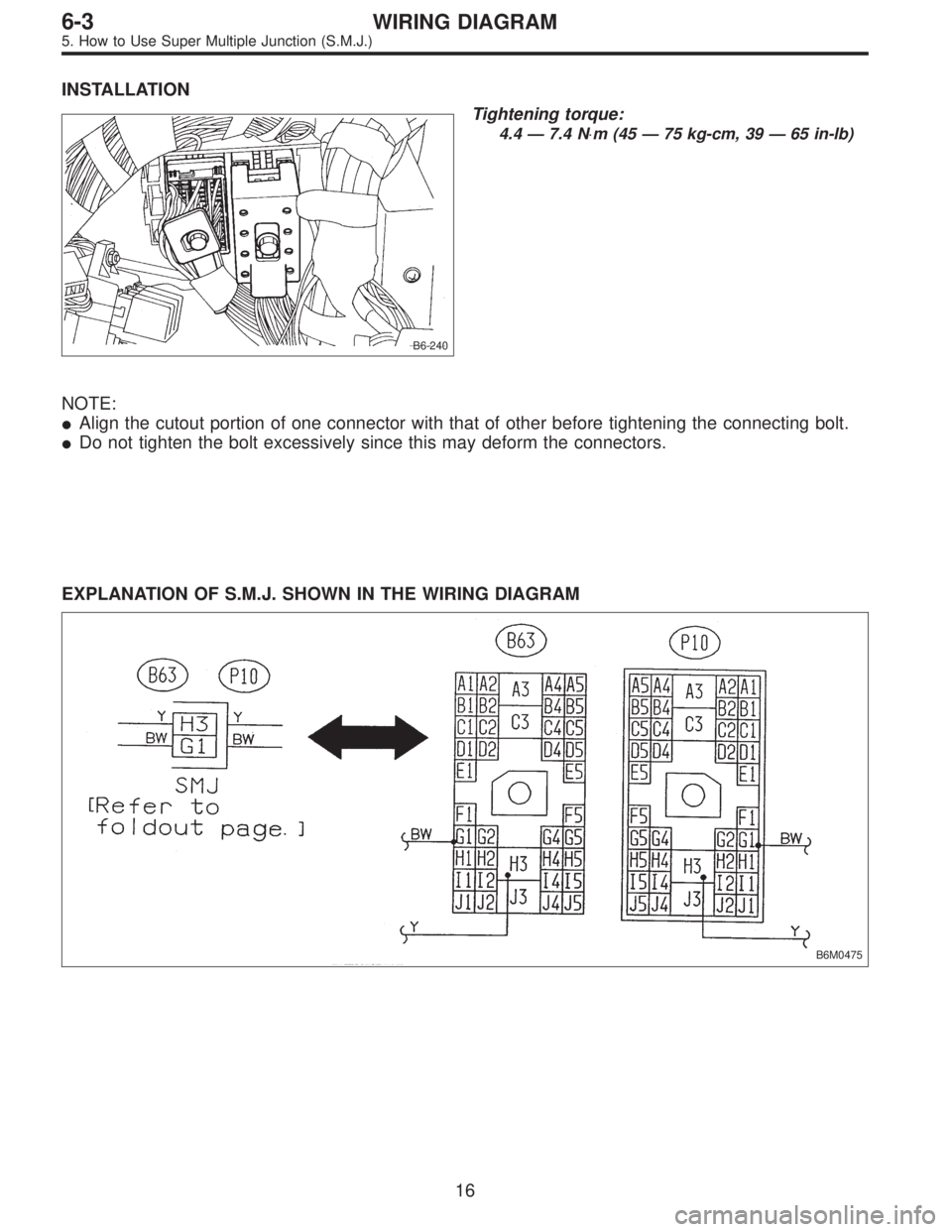
INSTALLATION
B6-240
Tightening torque:
4.4 — 7.4 N⋅m (45 — 75 kg-cm, 39 — 65 in-lb)
NOTE:
�Align the cutout portion of one connector with that of other before tightening the connecting bolt.
�Do not tighten the bolt excessively since this may deform the connectors.
EXPLANATION OF S.M.J. SHOWN IN THE WIRING DIAGRAM
B6M0475
16
6-3WIRING DIAGRAM
5. How to Use Super Multiple Junction (S.M.J.)
Page 2002 of 2248
INSTALLATION
B6-240
Tightening torque:
4.4 — 7.4 N⋅m (45 — 75 kg-cm, 39 — 65 in-lb)
NOTE:
�Align the cutout portion of one connector with that of other before tightening the connecting bolt.
�Do not tighten the bolt excessively since this may deform the connectors.
EXPLANATION OF S.M.J. SHOWN IN THE WIRING DIAGRAM
B6M0475
16
6-3WIRING DIAGRAM
5. How to Use Super Multiple Junction (S.M.J.)
Page 2102 of 2248
INSTALLATION
B6-240
Tightening torque:
4.4 — 7.4 N⋅m (45 — 75 kg-cm, 39 — 65 in-lb)
NOTE:
�Align the cutout portion of one connector with that of other before tightening the connecting bolt.
�Do not tighten the bolt excessively since this may deform the connectors.
EXPLANATION OF S.M.J. SHOWN IN THE WIRING DIAGRAM
B6M0475
16
6-3WIRING DIAGRAM
5. How to Use Super Multiple Junction (S.M.J.)
Page 2232 of 2248

�In this manual, the following symbols are used.
*: Selective part
�: Replacement part
: Should be lubricated with oil.
: Should be lubricated with grease.
: Sealing point
: Tightening torque
�WARNING, CAUTION, NOTE
�WARNING: Indicates the item which must be observed precisely during performance of maintenance ser-
vices in order to avoid injury to the mechanics and other persons.
�CAUTION: Indicates the item which must be followed precisely during performance of maintenance ser-
vices so as to avoid damage and breakage to the vehicle and its parts and components.
�NOTE: Indicates the hints, knacks, etc. which make the maintenance job easier.
�SPECIAL TOOLS
When any special tool is required to perform the job, it is identified by“ST”in the applicable illustration and its
part number is shown in the manual.
M1H0120
1. Procedures for adjusting backlash
1) Set steering wheel to the straight-ahead position.
2) Remove the exhaust pipe
3) Loosen the lock nut with ST.
�
{ST1 921650000 STEERING GEARBOX WRENCH
ST2 921550000 STEERING GEARBOX WRENCH
Description
(of job method)
Shows the part name
Shows the part number
Tells that two kinds of special tools are required.
When two or more kinds of special tools are required to do
a job, they are identified by ST1, ST2,......respectively.
�
��
5
Page 2245 of 2248
SERVICE
PROCEDURE
[W4o21
4-2
4
.
Front
and
Rear
Drive
Shafts
1
2
B4MO692A
ST
I
B4MO693A
Cage
IJIIIII
-
-
II
i1
-
I
Cut-outportion
G4M0284
°o
G4M0285
7)
Align
the
boot
end
of
the
smaller
diameter
with
the3rd
groove
in
the
driveshaft
as
shown
in
the
figure
.
10
Boot
T
Small
boot
band
~3
Shaft
8)
Tighten
boot
bands
using
ST,
torque
wrench
and
socket
flex
handle
.
ST
28099AC000
BOOT
BAND
PLIER
J)
Large
boot
band
(g)
Boot
03
Torquewrench
Socket
flex
handle
~5
U
FJ
Tightening
torque
:
Large
boot
band
152
Mm
(16
.0
kg-m,
116
ft-Ib)
or
more
Small
boot
band
133
N~m
(13
.6
kg-m,
98
ft-Ib)
or
more
9)
Place
DOJ
boot
at
thecenter
of
shaft
.
10)Insert
DOJ
cage
onto
shaft
.
NOTE
:
Insert
the
cage
with
the
cut-out
portion
facingthe
shaft
end,
since
the
cage
is
directional
.
11)
install
DOJ
inner
race
on
shaft
and
fit
snap
ring
with
pliers
.
NOTE
:
Confirm
that
the
snap
ring
is
completely
fitted
in
the
shaft
groove
.
5


Align
the
boot
end
of
the
smaller")