Page 1338 of 2248

One-way clutch (3-")
Overrunning clutch
Drive pinion
Crown gear
Axle shaft
Differential gear
Final gear
Seal pipe
Oil pump
High clutch
Band brake
Low & reverse clutch
Reverse clutch
One-way clutch (1-2)
One-way clutch (3-4)
Double oil seal
Input shaft
Output shaft
Planetary gear
Reduction gear
Drive plate
Torque converter one-way clutch
Lock-up facing
Lock-up damper
ATF deterioration
ATF level too high or too low
Differential gear oil level too high or too low
Engine performance
Engine speed signal
Parking brake mechanism
Problem parts
30 31 32 33 34 35 36 37 38 39 40 41 42 43 44 45 46 47 48 49 50 51 52 53 54 55 56 57 58 Symptom
�Engine brake is not effected when select
lever is in“3”or“2”range.
�Engine brake is not effected when select
lever is in“1”range.
Shift characteristics are erroneous.
��No lock-up occurs.
Vehicle cannot be set in“D”range power
mode.
“D”range power mode cannot be released.
�Parking brake is not effected.
�Shift lever cannot be moved or is hard to
move from“P”range.
Select lever is hard to move.
Select lever is too light to move (unreason-
able resistance).
�ATF spurts out.
�Differential oil spurts out.
��Differential oil level changes excessively.
� ���� � �Odor is produced from oil supply pipe.
���Shock occurs when select lever is moved
from“1”to“2”range.
�Slippage occurs when select lever is moved
from“1”to“2”range.
�� � �Shock occurs when select lever is moved
from“2”to“3”range.
��Slippage occurs when select lever is moved
from“2”to“3”range.
�� ��Shock occurs when select lever is moved
from“3”to“4”range.
�Slippage occurs when select lever is moved
from“3”to“4”range.
�� �Shock occurs when select lever is moved
from“3”to“2”range.
�Shock occurs when select lever is moved
from“D”to“1”range.
��Shock occurs when select lever is moved
from“2”to“1”range.
��Shock occurs when accelerator pedal is
released at medium speeds.
��Vibration occurs during straight-forward
operation.
Select lever slips out of position during
acceleration or while driving on rough terrain.
�Vibration occurs during turns (tight corner
“braking”phenomenon).
Front wheel slippage occurs during standing
starts.
Vehicle is not set in FWD mode.
30 31 32 33 34 35 36 37 38 39 40 41 42 43 44 45 46 47 48 49 50 51 52 53 54 55 56 57 58
132
2-7ON-BOARD DIAGNOSTICS II SYSTEM
10. General Diagnostics Table
Page 1340 of 2248
Item Page
P0705 RNG Transmission range sensor circuit malfunction 274
P0710 ATF Transmission fluid temperature sensor circuit malfunction 279
P0720 ATVSP Out")
DTC
No.Abbreviation
(Subaru select monitor)Item Page
P0705 RNG Transmission range sensor circuit malfunction 274
P0710 ATF Transmission fluid temperature sensor circuit malfunction 279
P0720 ATVSP Output speed sensor (vehicle speed sensor 1) circuit malfunction 281
P0725 ATNE Engine speed input circuit malfunction 283
P0731 GR
—1 Gear 1 incorrect ratio
285 P0732 GR
—2 Gear 2 incorrect ratio
P0733 GR
—3 Gear 3 incorrect ratio
P0734 GR
—4 Gear 4 incorrect ratio
P0740 LU
—F Torque converter clutch system malfunction 289
P0743 LU Torque converter clutch system electrical 294
P0748 PL Pressure control solenoid electrical 296
P0753 SFT1 Shift solenoid A electrical 298
P0758 SFT2 Shift solenoid B electrical 300
P0760 OVR
—F Shift solenoid C malfunction 302
P0763 OVR Shift solenoid C electrical 307
P1100 ST
—SW Starter switch circuit malfunction 309
P1101 N
—SW Neutral position switch circuit malfunction [MT vehicles] 311
P1101 N
—SW Neutral position switch circuit malfunction [AT vehicles] 315
P1102 BR Pressure sources switching solenoid valve circuit malfunction 319
P1103 TRQ Engine torque control signal circuit malfunction 325
P1104 TCS TCS signal circuit malfunction 328
P1500 FAN
—1 Radiator fan relay 1 circuit malfunction 331
P1502 FAN
—F Radiator fan function problem 338
P1700 ATTH Throttle position sensor circuit malfunction for automatic transmission 341
P1701 CRS Cruise control set signal circuit malfunction for automatic transmission 343
P1702 ATDIAG Automatic transmission diagnosis input signal circuit malfunction 346
134
2-7ON-BOARD DIAGNOSTICS II SYSTEM
11. Diagnostics Chart with Trouble Code
Page 1495 of 2248
OBD0605
AV: DTC P0740
—TORQUE CONVERTER CLUTCH SYSTEM
MALFUNCTION (LU
—F)—
DESCRIPTION:
The lock-up engaging and disengaging conditions are set
for each gear shift range, gear position and shift pattern
and correspond to the throttle position and vehicle speed,
and the duty solenoid is electronically controlled by TCM
controls the lock-up clutch. The lock-up clutch engagement
and disengagement are controlled by the lock-up control
valve.
DTC DETECTING CONDITION:
�Two consecutive trips with fault
TROUBLE SYMPTOM:
�No lock-up occurs. (after engine warm-up)
�No shift or excessive tight corner“braking”
289
2-7ON-BOARD DIAGNOSTICS II SYSTEM
11. Diagnostics Chart with Trouble Code
Page 1500 of 2248
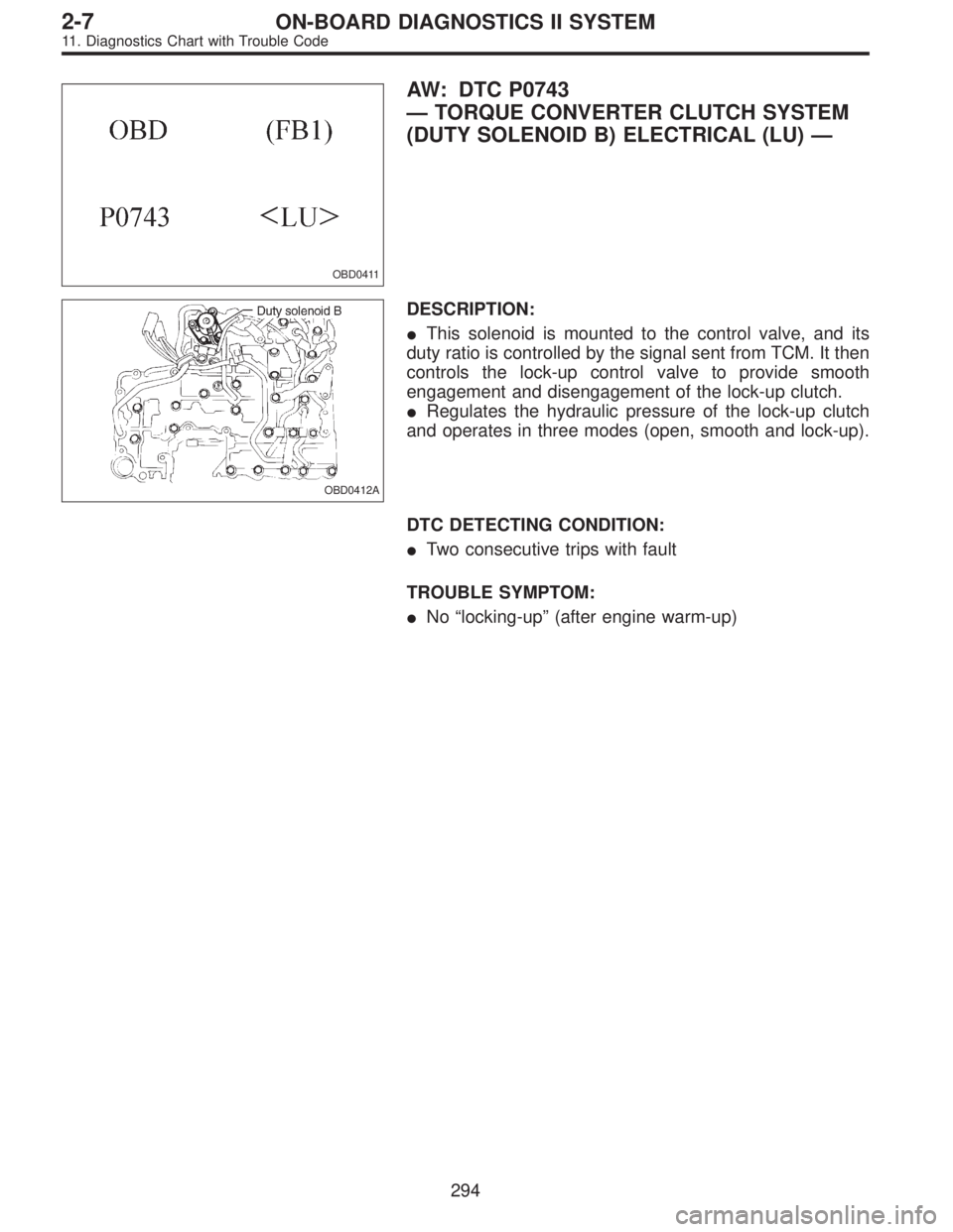
OBD0411
AW: DTC P0743
—TORQUE CONVERTER CLUTCH SYSTEM
(DUTY SOLENOID B) ELECTRICAL (LU)—
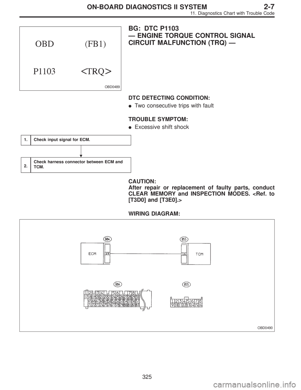
OBD0412A
DESCRIPTION:
�This solenoid is mounted to the control valve, and its
duty ratio is controlled by the signal sent from TCM. It then
controls the lock-up control valve to provide smooth
engagement and disengagement of the lock-up clutch.
�Regulates the hydraulic pressure of the lock-up clutch
and operates in three modes (open, smooth and lock-up).
DTC DETECTING CONDITION:
�Two consecutive trips with fault
TROUBLE SYMPTOM:
�No“locking-up”(after engine warm-up)
294
2-7ON-BOARD DIAGNOSTICS II SYSTEM
11. Diagnostics Chart with Trouble Code
Page 1531 of 2248
OBD0489
BG: DTC P1103
—ENGINE TORQUE CONTROL SIGNAL
CIRCUIT MALFUNCTION (TRQ)—
DTC DETECTING CONDITION:
�Two consecutive trips with fault
TROUBLE SYMPTOM:
�Excessive shift shock
1.Check input signal for ECM.
2.Check harness connector between ECM and
TCM.
CAUTION:
After repair or replacement of faulty parts, conduct
CLEAR MEMORY and INSPECTION MODES.
[T3D0] and [T3E0].>
WIRING DIAGRAM:
OBD0490
�
325
2-7ON-BOARD DIAGNOSTICS II SYSTEM
11. Diagnostics Chart with Trouble Code
Page 1562 of 2248
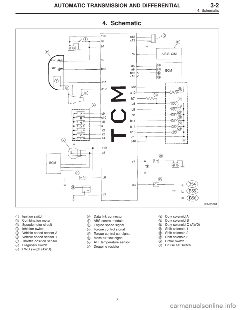
4. Schematic
B3M0376A
�1Ignition switch
�
2Combination meter
�
3Speedometer circuit
�
4Inhibitor switch
�
5Vehicle speed sensor 2
�
6Vehicle speed sensor 1
�
7Throttle position sensor
�
8Diagnosis switch
�
9FWD switch (AWD)�
10Data link connector
�
11ABS control module
�
12Engine speed signal
�
13Torque control signal
�
14Torque control cut signal
�
15Mass air flow signal
�
16ATF temperature sensor
�
17Dropping resistor�
18Duty solenoid A
�
19Duty solenoid B
�
20Duty solenoid C (AWD)
�
21Shift solenoid 1
�
22Shift solenoid 2
�
23Shift solenoid 3
�
24Brake switch
�
25Cruise set switch
7
3-2AUTOMATIC TRANSMISSION AND DIFFERENTIAL
4. Schematic
Page 1564 of 2248
Resistance to
body
(ohms)
Throttle position
sensorB54 8Throttle fully closed. 0.5±0.2
—
Throttle fully open. 4.6±0.3
Throttle positio")
ContentConnector
No.Terminal
No.Measuring conditionsVoltage
(V)Resistance to
body
(ohms)
Throttle position
sensorB54 8Throttle fully closed. 0.5±0.2
—
Throttle fully open. 4.6±0.3
Throttle position
sensor power
supplyB56 19Ignition switch ON
(With engine OFF)5.05±0.25—
ATF temperature
sensorB54 10ATF temperature 20°C(68°F) 3.45±0.55 2.1—2.9 k
ATF temperature 80°C (176°F) 1.2±0.2 275—375
Vehicle speed
sensor 1B54 12Vehicle stopped. 0
450—720
Vehicle speed at least 20 km/h (12
MPH)More than 1 (AC range)
Vehicle speed
sensor 2B56 11When vehicle is slowly moved at
least 2 meters (7ft).Less than 1)More than 9—
Engine speed
signalB54 5Ignition switch ON (with engine
OFF).More than 10.5
—
Ignition switch ON (with engine ON). 8—11
Cruise set signal B56 3When cruise control is set (SET
lamp ON).Less than 1
—
When cruise control is not set (SET
lamp OFF).More than 6.5
Torque control
signalB55 16 Ignition switch ON 5±1—
Torque control cut
signalB56 16 Ignition switch ON 6—9—
Mass air flow
signalB54 9 Engine idling after warm-up 0.5—1.2—
Shift solenoid 1 B55 141st or 4th gear More than 9
20—32
2nd or 3rd gear Less than 1
Shift solenoid 2 B55 131st or 2nd gear More than 9
20—32
3rd or 4th gear Less than 1
Shift solenoid 3 B55 15Select lever in“N”range (with
throttle fully closed).Less than 1
20—32
Select lever in“D”range (with
throttle fully closed).More than 9
Duty solenoid A B55 8Throttle fully closed (with engine
OFF) after warm-up.1.5—4.0
2.0—4.5
Throttle fully open (with engine
OFF) after warm-up.Less than 1
Dropping resistor B55 7Throttle fully closed (with engine
OFF) after warm-up.More than 8.5
12—18
Throttle fully open (with engine
OFF) after warm-up.Less than 1
Duty solenoid B B55 5When lock up occurs. More than 8.5
9—17
When lock up is released. Less than 0.5
Duty solenoid C
(AWD model only)B55 3Fuse on FWD switch More than 8.5
9—17 Fuse removed from FWD switch
(with throttle fully open and with
select lever in 1st gear).Less than 0.5
Sensor ground
line 1B54 7—0 Less than 1
Sensor ground
line 2B56 20—0 Less than 1
System ground
lineB56 1—0 Less than 1
Power system
ground lineB55 10—0 Less than 1
FWD switch
(AWD model only)B56 2Fuse removed. 6—9.1
—
Fuse installed. Less than 1
9
3-2AUTOMATIC TRANSMISSION AND DIFFERENTIAL
5. Transmission Control Module (TCM) I/O Signal
Page 1568 of 2248
Page
11 Duty solenoid ADetects open or shorted drive
circuit, as well as valve seizure.PLDTY 16
12 D")
D: LIST OF TROUBLE CODE
1. TROUBLE CODE
Trouble code Item Content of diagnosisAbbr.
(Select monitor)Page
11 Duty solenoid ADetects open or shorted drive
circuit, as well as valve seizure.PLDTY 16
12 Duty solenoid BDetects open or shorted drive
circuit, as well as valve seizure.LUDTY 20
13 Shift solenoid 3Detects open or shorted drive
circuit, as well as valve seizure.OVR 24
14 Shift solenoid 2Detects open or shorted drive
circuit, as well as valve seizure.SFT2 26
15 Shift solenoid 1Detects open or shorted drive
circuit, as well as valve seizure.SFT1 28
16 Torque control cut signalDetects open or shorted input
signal circuit.TQ.DS 30
21 ATF temperature sensorDetects open or shorted input
signal circuit.ATFT 32
22 Mass air flow signalDetects open or shorted input
signal circuit.AFM 36
23 Engine speed signalDetects open or shorted input
signal circuit.EREV 38
24 Duty solenoid CDetects open or shorted drive
circuit, as well as valve seizure.4WDTY 40
25 Torque control signalDetects open or shorted input
signal circuit.TQ.CT 42
31 Throttle position sensorDetects open or shorted input
signal circuit.THV 44
32 Vehicle speed sensor 1Detects open or shorted input
signal circuit.VSP1 48
33 Vehicle speed sensor 2Detects open or shorted input
signal circuit.VSP2 52
13
3-2AUTOMATIC TRANSMISSION AND DIFFERENTIAL
6. Diagnostic Chart for On-board Diagnostic System
—
DESCRIPTION:
The lock-up engaging and disengaging conditions are set
for each gear shift range, gear position and shift")