Page 1044 of 2248
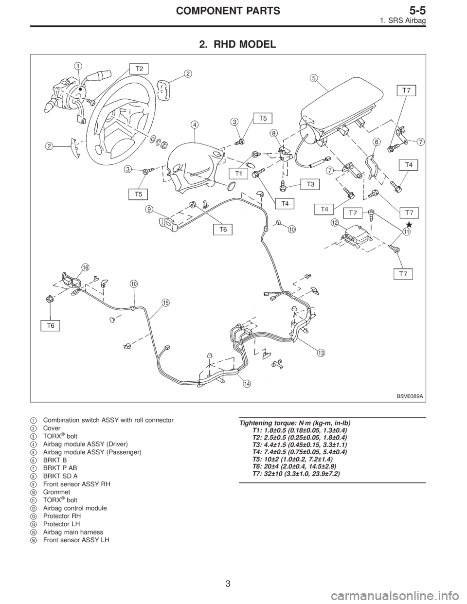
2. RHD MODEL
B5M0389A
�1Combination switch ASSY with roll connector
�
2Cover
�
3TORX®bolt
�
4Airbag module ASSY (Driver)
�
5Airbag module ASSY (Passenger)
�
6BRKT B
�
7BRKT P AB
�
8BRKT SD A
�
9Front sensor ASSY RH
�
10Grommet
�
11TORX®bolt
�
12Airbag control module
�
13Protector RH
�
14Protector LH
�
15Airbag main harness
�
16Front sensor ASSY LH
Tightening torque: N⋅m (kg-m, in-lb)
T1: 1.8±0.5 (0.18±0.05, 1.3±0.4)
T2: 2.5±0.5 (0.25±0.05, 1.8±0.4)
T3: 4.4±1.5 (0.45±0.15, 3.3±1.1)
T4: 7.4±0.5 (0.75±0.05, 5.4±0.4)
T5: 10±2 (1.0±0.2, 7.2±1.4)
T6: 20±4 (2.0±0.4, 14.5±2.9)
T7: 32±10 (3.3±1.0, 23.9±7.2)
3
5-5COMPONENT PARTS
1. SRS Airbag
Page 1067 of 2248

1. Engine Electrical
A: SPECIFICATIONS
Item Designation
StarterType Reduction type
ModelMT
TN128000-8311AT
TN128000-8321
Manufacturer NIPPONDENSO TENNESSEE
Voltage and output 12 V — 1.0 kW 12 V — 1.4 kW
Direction of rotation Counterclockwise (when observed from pinion)
Number of pinion teeth 8 9
No-load
characteristicsVoltage 11 V
Current 90 A or less
Rotating
speed3,000 rpm or more 2,900 rpm or more
Load
characteristicsVoltage 8 V
Current 280 A or less 370 A or less
Torque 9.8 N⋅m (1.0 kg-m, 7.2 ft-lb) 13.7 N⋅m (1.4 kg-m, 10.1 ft-lb)
Rotating
speed900 rpm or more 880 rpm or more
Lock
characteristicsVoltage 5 V
Current 800 A or less 1,050 A or less
Torque 27.5 N⋅m (2.8 kg-m, 20.3 ft-lb) or more
GeneratorType Rotating-field three-phase type, Voltage regulator built-in type
Model LR185-701H
Manufacturer HITACHI AUTOMOTIVE PRODUCTS
Voltage and output 12 V — 85 A
Polarity on ground side Negative
Rotating direction Clockwise (when observed from pulley side)
Armature connection 3-phase Y-type
Output current1,500 rpm — 35 A or more
2,500 rpm — 62 A or more
5,000 rpm — 82 A or more
Regulated voltage 14.5
+0.3
�0.4V [20°C (68°F)]
Ignition
coilModel F-569-01R
Manufacturer Diamond
Primary coil resistance 0.69Ω±10%
Secondary coil resistance 21.0 kΩ±15%
Insulation resistance between
primary terminal and caseMore than 10 MΩ
Spark
plugType and manufacturerRC10YC4 .......... CHAMPION
Alternate
(BKR6E-11 .......... NGK
K20PR-U11 .......... NIPPONDENSO)
Thread size mm 14, P = 1.25
Spark gap mm (in) 1.0 — 1.1 (0.039 — 0.043)
2
6-1SPECIFICATIONS AND SERVICE DATA
1. Engine Electrical
Page 1070 of 2248
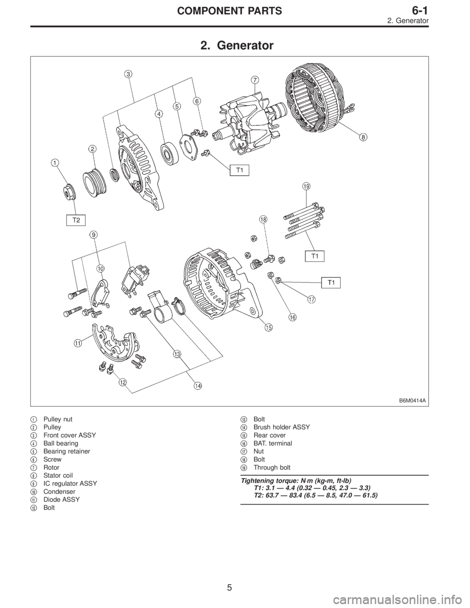
2. Generator
B6M0414A
�1Pulley nut
�
2Pulley
�
3Front cover ASSY
�
4Ball bearing
�
5Bearing retainer
�
6Screw
�
7Rotor
�
8Stator coil
�
9IC regulator ASSY
�
10Condenser
�
11Diode ASSY
�
12Bolt�
13Bolt
�
14Brush holder ASSY
�
15Rear cover
�
16BAT. terminal
�
17Nut
�
18Bolt
�
19Through bolt
Tightening torque: N⋅m (kg-m, ft-lb)
T1: 3.1 — 4.4 (0.32 — 0.45, 2.3 — 3.3)
T2: 63.7 — 83.4 (6.5 — 8.5, 47.0 — 61.5)
5
6-1COMPONENT PARTS
2. Generator
Page 1071 of 2248
G6M0095
1. Starter
A: REMOVAL AND INSTALLATION
1) Disconnect battery ground cable.
G2M0309
2) Disconnect connector and terminal from starter.
3) Remove starter from transmission.
4) Installation is in the reverse order of removal.
Tightening torque:
50±4 N⋅m (5.1±0.4 kg-m, 36.9±2.9 ft-lb)
B: TEST
1. MAGNETIC SWITCH
CAUTION:
�The following magnetic switch tests should be per-
formed with specified voltage applied.
�Each test should be conducted within 3 to 5 sec-
onds. Power to be furnished should be one-half the
rated voltage.
B6M0415A
1) Pull-in test
Connect two battery negative leads onto magnetic switch
body and terminal C respectively. Then connect battery
positive lead onto terminal 50. Pinion should extend when
lead connections are made.
B6M0416A
2) Holding-in test
Disconnect lead from terminal C with pinion extended. Pin-
ion should be held in the extended position.
6
6-1SERVICE PROCEDURE
1. Starter
Page 1072 of 2248
 Return test
Connect two battery negative leads onto terminal 50 and
onto switch body respectively. Then connect battery posi-
tive lead onto terminal C. Next, disconnect lead from ter-
min")
B6M0417A
3) Return test
Connect two battery negative leads onto terminal 50 and
onto switch body respectively. Then connect battery posi-
tive lead onto terminal C. Next, disconnect lead from ter-
minal 50. Pinion should return immediately.
2. PERFORMANCE TEST
The starter is required to produce a large torque and high
rotating speed, but these starter characteristics vary with
the capacity of the battery. It is therefore important to use
a battery with the specified capacity whenever testing the
starter.
The starter should be checked for the following three items:
1. No-load test
Measure the maximum rotating speed and current under a
no-load state.
2. Load test
Measure the magnitude of current needed to generate the
specified torque and rotating speed.
3. Stall test
Measure the torque and current when the armature is
locked.
B6M0418A
1) No-load test
Run single starter under no-load state, and measure its
rotating speed, voltage, and current, using the specified
battery. Measured values must meet the following stan-
dards:
No-load test (Standard):
Voltage/Current
11 V/90 A, or more
Rotating speed
TN128000-8311: 3,000 rpm, or more
TN128000-8321: 3,350 rpm, or more
7
6-1SERVICE PROCEDURE
1. Starter
Page 1073 of 2248
 Load test (For reference)
Perform this test to check maximum output of starter. Use
test bench which is able to apply load (brake) to starter.
Measure torque value and rotating speed under")
B6M0419A
2) Load test (For reference)
Perform this test to check maximum output of starter. Use
test bench which is able to apply load (brake) to starter.
Measure torque value and rotating speed under the speci-
fied voltage and current conditions while controlling brak-
ing force applied to starter.
CAUTION:
Change engagement position of overrunning clutch
and make sure it is not slipping.
Load test (Standard):
TN128000-8311
Voltage/Load
8 V/9.8 N⋅m (1.0 kg-m, 7.2 ft-lb)
Current/Speed
280 A max./900 rpm min.
TN128000-8321
Voltage/Load
8 V/13.7 N⋅m (1.4 kg-m, 10.1 ft-lb)
Current/Speed
370 A, or less/880 rpm, or more
B6M0420A
3) Stall test
Using the same test equipment used for load test, apply
brake to lock starter armature. Then measure voltage,
current, and torque values.
Measured values must meet the following standard.
Stall test (Standard):
TN128000-8311
Voltage/Current
5 V/800 A, or less
Torque
27.5 N⋅m (2.8 kg-m, 20.3 ft-lb) min.
TN128000-8321
Voltage/Current
5 V/1,050 A, or less
Torque
27.5 N⋅m (2.8 kg-m, 20.3 ft-lb) min.
NOTE:
Low rotating speed or excessive current during no-load test
may be attributable to high rotating resistance of starter
due to improper assembling.
Small current and no torque during stall test may be attrib-
utable to excessive contact resistance between brush and
commutator; whereas, normal current and insufficient
torque may be attributable to shorted commutator or poor
insulation.
Starter can be considered normal if it passes no-load and
stall tests; therefore, load test may be omitted.
8
6-1SERVICE PROCEDURE
1. Starter
Page 1088 of 2248

NGK: BKR6E-11
NIPPONDENSO: K20PR-U1")
3. Spark Plug
A: REMOVAL AND INSTALLATION
CAUTION:
All spark plugs installed on an engine, must be of the
same heat range.
Spark plug:
CHAMPION: RC10YC4
(Alternate)
NGK: BKR6E-11
NIPPONDENSO: K20PR-U11
1) Remove spark plug cords by pulling boot, not cord itself.
2) Remove spark plugs.
3) When installing spark plugs on cylinder head, use spark
plug wrench.
Tightening torque (Spark plug):
20.6±2.9 N⋅m (2.10±0.30 kg-m, 15.19±2.14 ft-lb)
CAUTION:
The above torque should be only applied to new spark
plugs without oil on their threads.
In case their threads are lubricated, the torque should
be reduced by approximately 1/3 of the specified
torque in order to avoid their over-stressing.
4) Connect spark plug cords.
G6M0086
B: INSPECTION
Check electrodes and inner and outer porcelain of plugs,
noting the type of deposits and the degree of electrode
erosion.
G6M0087
1) Normal
Brown to grayish-tan deposits and slight electrode wear
indicate correct spark plug heat range.
22
6-1SERVICE PROCEDURE
3. Spark Plug
Page 1098 of 2248

1. Precaution
�Before disassembling or reassembling parts, always
disconnect battery ground cable. When repairing
radio, control modules, etc. which are provided with
memory functions, record memory contents before
disconnecting battery ground cable. Otherwise, these
contents are cancelled upon disconnection.
�Reassemble parts in reverse order of disassembly
procedure unless otherwise indicated.
�Adjust parts to specifications contained in this
manual if so designated.
�Connect connectors and hoses securely during
reassembly.
�After reassembly, ensure functional parts operate
smoothly.
CAUTION:
�Airbag system wiring harness is routed near the
electrical parts and switch.
�All Airbag system wiring harness and connectors
are colored yellow. Do not use electrical test equip-
ment on these circuit.
�Be careful not to damage Airbag system wiring har-
ness when servicing the ignition key cylinder.
G6M0102
2. Battery
A: REMOVAL AND INSTALLATION
1. BATTERY
1) Disconnect the positive (+) terminal after disconnecting
the negative (�) terminal of battery.
2) Remove flange nuts from battery rods and take off bat-
tery holder.
3) Remove battery.
Tightening torque:
3.4±1.0 N⋅m (0.35±0.1 kg-m, 2.5±0.7 ft-lb)
NOTE:
�Clean battery cable terminals and apply grease to retard
the formation of corrosion.
�Connect the positive (+) terminal of battery and then the
negative (�) terminal of the battery.
4
6-2SERVICE PROCEDURE
1. Precaution - 2. Battery
 Disconnect battery ground cable.
G2M0309
2) Disconnect connector and terminal from starter.
3) Remove starter from transmission.
4) Installation is in")