Page 89 of 2248
G2M0185
3) Apply fluid packing to the mating surface of #1 and #3
cylinder block, and position it on #2 and #4 cylinder block.
Fluid packing:
THREE BOND 1215 or equivalent
CAUTION:
Do not allow fluid packing to jut into O-ring grooves,
oil passages, bearing grooves, etc.
B2M0088A
4) Temporarily tighten 10 mm cylinder block connecting
bolts in numerical order shown in Figure.
5) Tighten 10 mm cylinder block connecting bolts in
numerical order.
Tightening torque:
47±3 N⋅m (4.8±0.3 kg-m, 34.7±2.2 ft-lb)
B2M0089A
6) Tighten 8 mm and 6 mm cylinder block connecting bolts
in numerical order shown in Figure.
Tightening torque:
�
1—�7: 25±2 N⋅m
(2.5±0.2 kg-m, 18.1±1.4 ft-lb)
�
8: 6.4 N⋅m (0.65 kg-m, 4.7 ft-lb)
G2M0186
7) Install rear oil seal by using ST1 and ST2.
ST1 499597100 OIL SEAL GUIDE
ST2 499587200 OIL SEAL INSTALLER
68
2-3SERVICE PROCEDURE
7. Cylinder Block
Page 90 of 2248
3. PISTON AND PISTON PIN (#1 AND #2)
B2M0128A
Tightening torque: N⋅m (kg-m, ft-lb)
T: 69±7 (7.0±0.7, 50.6±5.1)
G2M0188
1) Installing piston
(1) Turn cylinder block so that #1 and #2 cylinders face
upward.
(2) Using ST1, turn crankshaft so that #1 and #2 con-
necting rods are set at bottom dead center.
ST1 499987500 CRANKSHAFT SOCKET
(3) Apply a coat of engine oil to pistons and cylinders
and insert pistons in their cylinders by using ST2.
ST2 498747100 PISTON GUIDE
G2M0189
2) Installing piston pin
(1) Insert ST3 into service hole to align piston pin hole
with connecting rod small end.
CAUTION:
Apply a coat of engine oil to ST3 before insertion.
ST3 499017100 PISTON PIN GUIDE
69
2-3SERVICE PROCEDURE
7. Cylinder Block
Page 92 of 2248
4. PISTON AND PISTON PIN (#3 AND #4)
B2M0129A
Tightening torque: N⋅m (kg-m, ft-lb)
T1: 6.4 (0.65, 4.7)
T2: 69±7 (7.0±0.7, 50.6±5.1)
Turn cylinder block so that #3 and #4 cylinders face
upward. Using the same procedures as used for #1 and #2
cylinders, install pistons and piston pins.
71
2-3SERVICE PROCEDURE
7. Cylinder Block
Page 93 of 2248
E: INSTALLATION
1. OIL PUMP AND ENGINE COOLANT PUMP
B2M0124B
Tightening torque: N⋅m (kg-m, ft-lb)
T1: 5 (0.5, 3.6)
T2: 6.4 (0.65, 4.7)
T3: 10 (1.0, 7)
T4: 72±3 (7.3±0.3, 52.8±2.2)
T5: First 12±2 (1.2±0.2, 8.7±1.4)
Second 12±2 (1.2±0.2, 8.7±1.4)
72
2-3SERVICE PROCEDURE
7. Cylinder Block
Page 102 of 2248
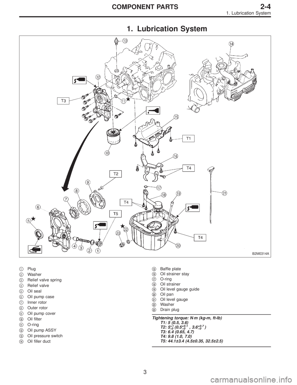
1. Lubrication System
B2M0314A
�1Plug
�
2Washer
�
3Relief valve spring
�
4Relief valve
�
5Oil seal
�
6Oil pump case
�
7Inner rotor
�
8Outer rotor
�
9Oil pump cover
�
10Oil filter
�
11O-ring
�
12Oil pump ASSY
�
13Oil pressure switch
�
14Oil filler duct�
15Baffle plate
�
16Oil strainer stay
�
17O-ring
�
18Oil strainer
�
19Oil level gauge guide
�
20Oil pan
�
21Oil level gauge
�
22Washer
�
23Drain plug
Tightening torque: N⋅m (kg-m, ft-lb)
T1: 5 (0.5, 3.6)
T2: 5
+1
�0(0.5+0.1
�0, 3.6+0.7
�0)
T3: 6.4 (0.65, 4.7)
T4: 9.8 (1.0, 7.0)
T5: 44.1±3.4 (4.5±0.35, 32.5±2.5)
3
2-4COMPONENT PARTS
1. Lubrication System
Page 106 of 2248
B2M0315B
2) Install inner and outer rotors in their original positions.
3) Install oil relief valve and relief spring.
4) Install oil pump cover.
Tightening torque:
T1: 5
+1
�0N⋅m (0.5+0.1
�0kg-m, 3.6+0.7
�0ft-lb)
T2: 44.1±3.4 N⋅m (4.5±0.35 kg-m, 32.5±2.5 ft-lb)
B2M0319A
E: INSTALLATION
Installation is in the reverse order of removal.
Do the following:
1) Apply fluid packing to matching surfaces of oil pump.
Fluid packing:
THREE BOND 1215 or equivalent
2) Replace O-ring with a new one.
3) Be careful not to scratch oil seal when installing oil
pump on cylinder block.
CAUTION:
Apply fluid packing to oil pressure switch threads
before installation.
Fluid packing:
THREE BOND 1215 or equivalent
7
2-4SERVICE PROCEDURE
1. Oil Pump
Page 109 of 2248
G2M0376
15) Remove oil strainer.
G2M0377
16) Remove baffle plate and oil strainer stay.
B: INSPECTION
By visual check make sure oil pan, oil strainer, oil strainer
stay and baffle plate are not damaged.
G2M0377
C: INSTALLATION
CAUTION:
Before installing oil pan, clean sealant from oil and
engine block.
1) Install baffle plate and oil strainer stay.
Tightening torque:
5N⋅m (0.5 kg-m, 3.6 ft-lb)
G2M0376
2) Install oil strainer onto baffle plate.
CAUTION:
Replace O-ring with a new one.
Tightening torque:
9.8 N⋅m (1.0 kg-m, 7 ft-lb)
10
2-4SERVICE PROCEDURE
2. Oil Pan and Oil Strainer
Page 110 of 2248
G2M0082
3) Hold oil strainer to oil strainer stay.
Tightening torque:
9.8 N⋅m (1.0 kg-m, 7 ft-lb)
G2M0084
4) Apply fluid packing to mating surfaces and install oil
pan.
Fluid packing:
THREE BOND 1207C or equivalent
G2M0081
5) Tighten bolts which install oil pan onto engine block.
Tightening torque:
9.8 N⋅m (1.0 kg-m, 7 ft-lb)
G2M0293
6) Lower engine onto front crossmember.
7) Tighten nuts which install front cushion rubber onto front
crossmember.
Tightening torque:
69±15 N⋅m (7.0±1.5 kg-m, 51±11 ft-lb)
B2M0054
8) Install front exhaust pipe.
CAUTION:
Always use the new gaskets.
(1) Place front exhaust pipe on bracket.
(2) Tighten nuts which install front exhaust pipe on
engine.
Tightening torque:
30±5 N⋅m (3.1±0.5 kg-m, 22.4±3.6 ft-lb)
11
2-4SERVICE PROCEDURE
2. Oil Pan and Oil Strainer
 Apply fluid packing to the mating surface of #1 and #3
cylinder block, and position it on #2 and #4 cylinder block.
Fluid packing:
THREE BOND 1215 or equivalent
CAUTION:
Do not allow fluid")

B2M0128A
Tightening torque: N⋅m (kg-m, ft-lb)
T: 69±7 (7.0±0.7, 50.6±5.1)
G2M0188
1) Installing piston
(1) Turn cylinder block so that #1 and #2 cylinders fac")

B2M0129A
Tightening torque: N⋅m (kg-m, ft-lb)
T1: 6.4 (0.65, 4.7)
T2: 69±7 (7.0±0.7, 50.6±5.1)
Turn cylinder block so that #3 and #4 cylinders face
upward. Us")

T1: 5 (0.5, 3.6)
T2: 6.4 (0.65, 4.7)
T3: 10 (1.0, 7)
T4: 72±3 (7.3±0.3, 52.8±2.2)
T5: First 12±2")
 Install inner and outer rotors in their original positions.
3) Install oil relief valve and relief spring.
4) Install oil pump cover.
Tightening torque:
T1: 5
+1
�0N⋅m (0.5+0.1
�0kg-m, 3")
 Remove oil strainer.
G2M0377
16) Remove baffle plate and oil strainer stay.
B: INSPECTION
By visual check make sure oil pan, oil strainer, oil strainer
stay and baffle plate are not damage")
 Hold oil strainer to oil strainer stay.
Tightening torque:
9.8 N⋅m (1.0 kg-m, 7 ft-lb)
G2M0084
4) Apply fluid packing to mating surfaces and install oil
pan.
Fluid packing:
THREE BOND 120")